When you click on links to various merchants on this site and make a purchase, this can result in this site earning a commission. Affiliate programs and affiliations include, but are not limited to, the eBay Partner Network.
Hazards on constantly, wipers on constantly when key is turned on
First off, 87 GXL MT complete restoration job, mice got in during 2 year sit and really messed things up. I do not have the anti-theft control module under under the glove box on the back of the speaker dash piece.
What my issues are currently -
-Hazards on at all times if ECU sees power
-Wipers are on constantly if key is put in ACC or ON position
-Aftermarket stereo will not power on(used FSM to wire in new stereo via old connectors etc.) Just running Power, ACC, and Ground from original system, all other wiring is brand new for remote amp in rear seats along with custom remote wire for power antenna.
-Passenger side headlight won't pop up, it does turn on though - don't think that has anything to do with the problem but maybe it does (never had pop ups before) drivers side does pop up though with both headlight dial and headlight button
-Horn, attempting to use the Additional Horn connector in the factory harness but to no luck, I also don't know what fuse powers the horn as I cannot find anything labelled 'HORN'
What does work -
-All lights, including dash, headlights, turn signals, brakes, reverse, warning, yada yada
-Warning cluster works, buzzers work, get low coolant cause system is still empty (haven't started the car yet)
-All the ***** and dials on the dash, including Logicon, blower motors, etc.
-Starter works
-All fuses in both fuse blocks
-Ignition works, doesn't lock me out of doing anything
-Door locks work, again doesn't lock me out, they are manual door locks though, drivers door has connector that is hooked up
What has been removed from the car -
-AAS - controller, module, and controllers on top of struts all removed
-Original stereo equipment from all 4 corners, including passenger side dash amp, no door speakers
-Hood switch, there is no connector on the hood latch so removed that connector from the front chassis harness
-Emissions components, cold start assist, oil metering pump
But here's my question, what is causing everything to work, that needs to work for the time being, but make my hazards go off constantly as well as my wipers when the key is on? Is there another system in the car that can cause these issues that isn't the anti-theft? Assuming wipers aren't related to anti-theft that is. Could it just be a coincident that both are acting up and making me think some sort of security system is going off? I've read about the hazard switch acting up at the dash but don't want to just unplug it thinking the switch is bad and not fix the actual problem if there is one. And again I could simply unplug the wiper motor but don't want to ignore an actual problem if there is one.
-So did I wire in the stereo wrong? Was there some wire I needed to ground or something from the OEM stereo/AMP?
-Is there an issue with removing the AAS?
-Something I'm not thinking of at all?
-Or just those two issues side by side tricking my brain into thinking it's more complicated than it really is?
Thanks in advance, any help would be great, pretty much everything I've found through searching has been the opposite of my issues, meaning wipers and hazards don't work. I've seen posts about aftermarket stereos not working but mostly seem to be linked to the Anti-Theft system which my car doesn't have installed on it.
Brandon
Last edited by Zeroto300; Jan 25, 2018 at 02:03 AM.
Reason: Text Formatting
sounds like you need an exorcist, i have never heard of such a problem.
the wipers sometimes won't park if the motor is corroded internally, since there is a park metal reluctor inside the motor and they will continue to run as they can't find the park position.
Last edited by insightful; Jan 25, 2018 at 10:09 PM.
All your symptoms point in one direction...and I don't mean the band either...
Check your Body CPU. Unplug it and your problems should stop. Now to fix it...that's another task! There is a separate Flasher CPU within the Body CPU case. It's a small circuit card that is pulled out from below. The Wipers and such are a function of the main board, which is found under the long 'surf board' panel. Remove both circuit board and inspect. Take pictures then post as needed. Either capacitors, a burned up solder run, microcircuit, or combination of each may need to be replaced.
You could be lucky in finding a Body CPU as they are fairly rare to get. These units aren't cheap and Mazda (if memory serves me well) no longer carries them. Check Atkins Rotary or even shoot Ray Crowe an email.
'Gen2n3', that’s actually exactly where I ended up, looking through the FSM many of the things I’m having issues with run into the CPU, after checking the Switch on the dash (right of the steering wheel) everything checked out there so it’s either wiring or the CPU. 'insighful', I still need to check Wiper motor and what not but I can simply just leave it unplugged for now. With the CPU out and apart looks good at first run through but would love to compare specs with a working one (continuity, voltage, etc.) or even swap with a working one just to test if that solves my problem. But before any of that I need to do some more testing on the wiring and connectors, see if it’s the signal coming into the CPU or the CPU relays themselves. After pricing them I’d rather it be the wiring haha. Since I had to rewire maybe 70% of the car I can’t assume I did everything perfect so checking that first, make some jumps and do some voltage/continuity testing to rule those things out.
Hopefully I get my results up here by the end of the day.
I believe the relays inside the wiper switch will need to be replaced. You can send your unit out for repair. Check out 13B Etc - Mazda RX-7 Parts And More. Their cost of repair is worth it, IMO. They repaired the switch in my Vert a few years ago and has been working like a champ ever since. Their turn around time is very good. My old 91 Coupe had the same repair done by Icemark, may they both rest in peace.
What was the cause to rewire a good portion of your car's wiring? Do you have good documentation of the repairs so you may refer back to in instances like this? The older I get, the harder it is to remember certain mods or wire re-routes. Certainly recheck your wires, especially if it involves the wipers or other items you disclosed above.
Be aware that the Body CPU is susceptible to failure. It's not like XBox360 RROD failure but similar. I had to replace 4 Body CPUs in 3 RX-7s; 3 in 2 FCs and 1 in an FD. They mostly failed for anti-theft circuit. One blew up from an unwitting relative who cross-wired a dead battery to jump start it. If I were in your shoes, I would plan to source a Body CPU. If the original can be repaired then consider it a bonus!
If you like, take some photos of the main CPU & flasher CPU boards and post them here. Take front + back side shots. I may be able to help spot a problem.
At first glance with the Wiper it does look to be internal but further testing will tell me for sure if that is the case. To be honest though not too worried about the wipers until the car runs as here in Phoenix we don’t get much rain haha. The car, previous to me purchasing it, had sat for a couple of years and mice got into it and really wreaked havoc. Ate through the entire front chassis harness in one area and chewed through the both the emissions and engine harness in many areas, so spent a lot of time rerunning wires and reading FSM Wiring Diagrams to figure out what went where.
I’m honestly just bringing it back up to factory status minus some stuff, not going crazy with anything just yet, so basically FSM will cover everything I have in the car now except battery relocation and custom stereo system. But I do have a giant parts list and “Things to do” as I went along, and just making it easier for myself for much later when I do intend to change things up, so many labels. But also stripped the car of a lot of the “less than ideal” features that either didn’t work anymore (AAS)/were a bad idea on Mazda’s part (spraying coolant into the intake, really?)/or just didn’t want anymore (OMP).
So after doing many of the tests listed in the FSM it’s basically ruled down to the CPU board for the Hazards/Turn Signal. Got my Horn working through the factory wires, ended up being a really dirty connection between the spring-loaded rod riding on the copper ring on the back of the steering wheel. Also, many of the warning lights work that are on that board, as well as the brake light board so the rest of the CPU is good to go. I'll try and get some good pics tomorrow up on here of the board, maybe i'll notice something while i'm doing so.
Alright so after a bunch more tests and re-doing tests the problem is the CPU Hazard board, so that has to get fixed, still need to get some pics up here. Wiper motor tested and shown to be working correctly actually, now i'm getting the issue where only Low works from the switch, saw a bunch of posts on that issue on here so i'll been looking at those to see what the consensus is on that issue. But have no clue what was causing my original issue with the wipers as after testing the motor and plugging it back in I no longer had them going off anytime the Key was at ACC or ON. I did test the wiper switch in the dash at the very beginning of my testing spree and that all checked out which is why I was originally thinking it was the Wiper motor.
Yes you are correct 'insightful' saw that in the FAQ cause I knew it was on here somewhere.
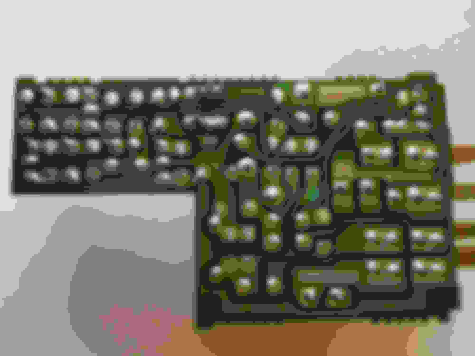
Not sure how much you can see in the pictures but I took a couple, I'll do an OHM test on all the contacts and see if it's an internal thing with a capacitor or something. Sorry they are so large, didn't edit them before putting them up.
But thank you all for helping out, always nice to get input from others.
Last edited by Zeroto300; Feb 1, 2018 at 10:48 PM.
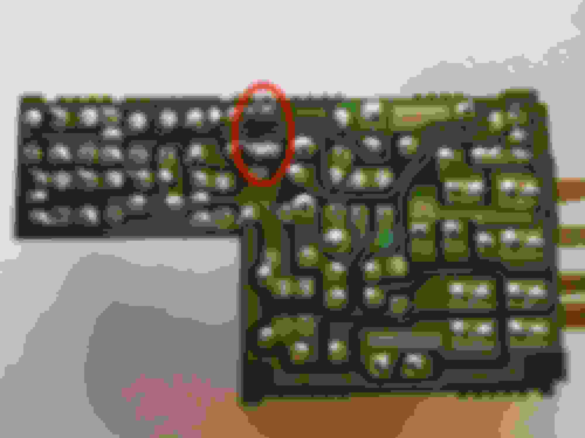
These solder joints in the red circle have been replaced before. This denotes a component or two that has been replaced. Could you identify what components are connected to these solder joints? Take some additional photos of that area from different angles. Shine a flashlight in key spots to eliminate shading from other components. Take resistance measurements of the 2 resistors that are standing up and to the right from transistor Q1. Those may be the replaced components. Do you know how to read a resistor color code? That is an easy google search, if not.
The good news is the capacitors all look healthy, the top covers are not bulged out and no electrolyte leaked from them. Do you know if this board was replaced or repaired before?
Cheers,
George
These solder joints are new when compared to the rest on the board. The components above were replaced before.
From what I know about the car after a complete chassis teardown and rebuild and from what the seller told me, this was a 1 owner car, older woman, not a single non-stock/factory recommended piece of equipment on the entire car. Based on that my best guess is this was done by a Mazda dealership/specialist.
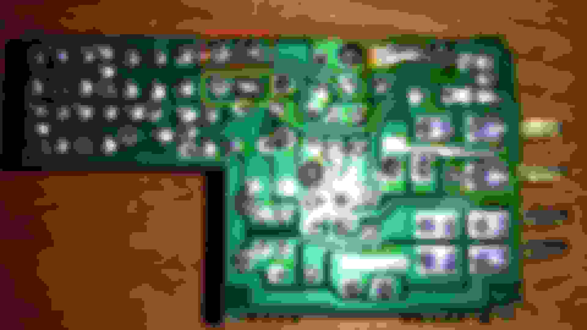
So after checking the resistance on these resistors I wonder if its an issue that the solder on these connections are melted together? Not sure if it's causing anything out of the normal operation of the board. Resistance was 41.3 Ohms across the resistors, again as they are soldered together as seen in the photo so I also tested them above the board, on both sides of the resistor and got the same reading from both.
Thanks for the additional photos. I don't see anything unusual underneath the coils. I cannot read the resistor color codes properly on those 2 resistors. Based upon your measurement of 41.3 ohms they could be in parallel. I also want to make sure, is it 41 ohms or 41k ohms? Theoretically, what is the total resistance of these 2 parallel resistors?
You could de-solder those joints then apply new solder to them. This would ensure no cold solder joints exists. Additionally, it looks like those joints are supposed to touch one another. They share the same solder runs on each side. You could also measure them separately once all the solder is removed from the joints.
Are there any other unusual solder joints on the board?
FWIW, here is a photo of my spare flasher CPU from my 91 Vert. Make sure that the resistor solder joints within the red box only touch each other. The solder should not touch the left joint. It shouldn't matter because they share the same trace but let's keep things consistent! Contacts within the yellow box touch one another.
I also took a measurement of those 2 resistors, R2 and R3. And I couldn't get a constant value. A capacitor must be in line because the values either went up or down to 0. Based upon the resistor color bands, R2 has Brown, Brown, Red, Gold. That equals a 1.1k ohm resistor. R3 has Blue, Red, Black, Gold. That equals a 62 ohm resistor.
R2 color code = Brown, Brown, Red, Gold
R3 color code = Blue, Red, Black, Gold
If they were connected in parallel and isolated then the total resistance would be 58.69 ohms. Formula+work below:
Rt = 1/(1/r1+1/r2+...)
Rt=1(1/1100+1/62)
Rt=1(0.000909091+0.016129032)
Rt=1(0.017038123)
Rt=58.6919 Ohms
Note, these components are from a 1991 Vert's Body CPU (FC66) which is different than the Body CPU from the Coupe. The flasher CPU may be identical. The number on the board is labeled R-31820.
CONFIRMED: Your Flasher CPU has the same part number of R-31820. These 2 boards are identical.
Cheers,
George
Last edited by Gen2n3; Feb 8, 2018 at 06:38 PM.
Reason: Confirmation statement added.
When in doubt, I just de-solder the resistors and test individually or just plain replace them. Be VERY careful to remove all solder and not overheat the trace, and avoid using force to remove the component. Sometimes the trace 'pad' comes off the board. You want to try your best to avoid this.
OP, you may have a local place that sells all kinds of electronic components. Worth looking.
Thanks for the info, been a bit busy lately, and still just trying to get the car to start. I will definitely look for some threads on soldering on these boards and possibly look at a local shop, done plenty of soldering but never on circuit boards.
As far as the Ohm reading goes is was just 41.3 ohms, not 41.3k ohms.
My color code based on the way yours is would be:
R2 - Yellow, Orange, Black, Gold
R3 - Brown, Brown, Red, Gold
Therefore, the resistance measurement you took verifies that these 2 resistors are in parallel with each other. It shouldn't matter from a mathematical perspective however, when compared to my example, it looks like your R3 is swapped with R2. It is possible that the voltage drop across each resistor may affect the circuit differently. Did the Body CPU fully function before your restoration project? Did you get that Body CPU from another source? Was this board modified to use LED bulbs?
It is unusual to see the same board (our part numbers for the board are identical) with resistance values in different positions, i.e. R3 value in R2 position. Equally unusual is the total resistance between your board and mine vary significantly. Also remember that I could not get a constant measurement from my board.
I propose 2 options:
1. Remove the 1.1k Ohm resistor from your R3 and install it in R2. Then get a 62 Ohm* resistor and install it in R3. Once completed, test your results.
2. Verify resistor values and positions with another forum member. If that other example is similar to mine then proceed with Option 1, otherwise, mimic the 2nd source.
* - The 62 Ohm resistor has a 5% tolerance. That's what the Gold band represents.
If you plan on soldering yourself then please refer to advice from this thread and from my thread on general soldering; it is found here: General Soldering Tips
To forum members reading this thread, would you be able to assist in verifying R2 & R3 values from the flasher CPU (found in the Body CPU)? And please indicate what Flasher Board you have, reference Brandon's pictures above.
So quick update I've recently bought the new resistors and have installed them into the board, switching the one from R3 into R2 and getting a proper 62 Ohm, 5% tolerance, 1/4 watt capacitor for R3. Now I did notice some things about the problem that I just hadn't run into previously. With the ECU and gauges switches unplugged completely, if the board receives power (ign to ON) the hazards come on. Not sure if this confirms or denies anything. I am getting a known working board hopefully it'll arrive later this week and I can just plug it in to see if anything changes. If nothing changes I know it's wiring related and if it does work then nothing I could've done from the start unless I spent the time to study the board indefinitely and test every little thing.
I'll be sure to update what happens with the new board, hoping it just fixes it, it'd be nice to have one less problem with this car.
...switching the one from R3 into R2 and getting a proper 62 Ohm, 5% tolerance, 1/4 watt capacitor for R3.
Brandon,
I presume you meant to say "resistor" for R3 and not "capacitor"? They are completely 2 different components! Regardless, I am looking forward to reading about your progress. Best of luck to you!
Alright so sorry for the delay, been dealing with injectors not working due to the CAS being in the hole but working when out of the hole issue for awhile.
Got the new board from Mazdatrix, did not fix the hazards issue, although did notice that now my "key in ignition with door open" chime goes off all the time as long as the key is in the ignition and the door is open, even when turned to ACC or ON, found that strange. I do have one question about the grounds that are behind the gauge cluster that sit on top of the steering column bracket or whatever. There are two ground terminals and they are attached to the same grounding point on my car, I couldn't for the life of me remember how the grounds were setup when I took the car apart originally. But left myself little reminders and also the harness just lined back up nicely to where this went back in. But is that how it should be? Kind of the one thing that bothers me all the time that maybe it's not correct. I also need to post Voltage signals for each Pin on the Flasher CPU board. seems like I'm having a bunch of wiring issues cause every time I test a component it always checks out.
The door chime should sound when a door is open, key is in the ignition, and/or key is turned to ACC. It should also stop sounding after a few seconds when the ignition switch is set to ON.
After replacing the resistors on your flasher CPU, did the problem with your hazards change at all? Or was it unchanged? If no change happened then you must dive into the wiring harnesses. If you claimed mice tore into the wiring then I don't envy your task! Please refresh my memory - is the hazard switch good?
I cannot answer the ground point question because I had no experience in tearing out an FC cluster. Perhaps another member could chime in to answer that question?
After replacing the resistors on my board the moment it gets power, with just battery hooked up, hazards start to flash. Same with the new board from Mazdatrix. I've tested the hazard switch several times but it always shows to be working correctly. I even tested the boards without the hazard switch hooked up and they still constantly flashed. At this point it's gotta be the wiring and I just need to get into the harness again and see where the tests take me. Are the grounds for the CPU at that weird connector on the backside of the driver's side shock tower? That is just a 6 Pin White connector?