
Fuel cut switch with LED

Fuel cut switch with LED
So I bought an illuminated rocker switch to use as a fuel cut switch on my wifes car, 88 SE Automatic
The switch has 3 terminals. Earth, Load, and Supply.
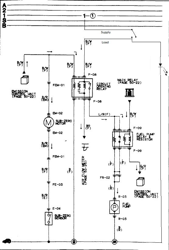
Seemed simple enough. I located the fuel pump relay under the dash, and split the black/white wire in the middle and wired:
Load to the wire coming from the plug/relay
Supply to the wiring harnes
Earth to ground
On the switch it shows a diagram, Supply and load are switched, then between load and earth it shows the LED. My goal was to have the LED come on only when the switch is turned on.
What ended up happening is the light turned on when the switch was on, turned off when the switch was off. Turned the switch back on, the light turned on for a moment then shut off. I blew the 15a Engine fuse.
Anybody know where I went wrong?
The switch has 3 terminals. Earth, Load, and Supply.
Seemed simple enough. I located the fuel pump relay under the dash, and split the black/white wire in the middle and wired:
Load to the wire coming from the plug/relay
Supply to the wiring harnes
Earth to ground
On the switch it shows a diagram, Supply and load are switched, then between load and earth it shows the LED. My goal was to have the LED come on only when the switch is turned on.
What ended up happening is the light turned on when the switch was on, turned off when the switch was off. Turned the switch back on, the light turned on for a moment then shut off. I blew the 15a Engine fuse.
Anybody know where I went wrong?
I wired the same switch to function as a fuel cut-off switch. The LED on my switch lit once and then never lit up again. Mine didn't blow a fuse, though. I just didn't worry about it lighting up after that... It was still functional.
I found this diagram on Google. Hopefully this helps.
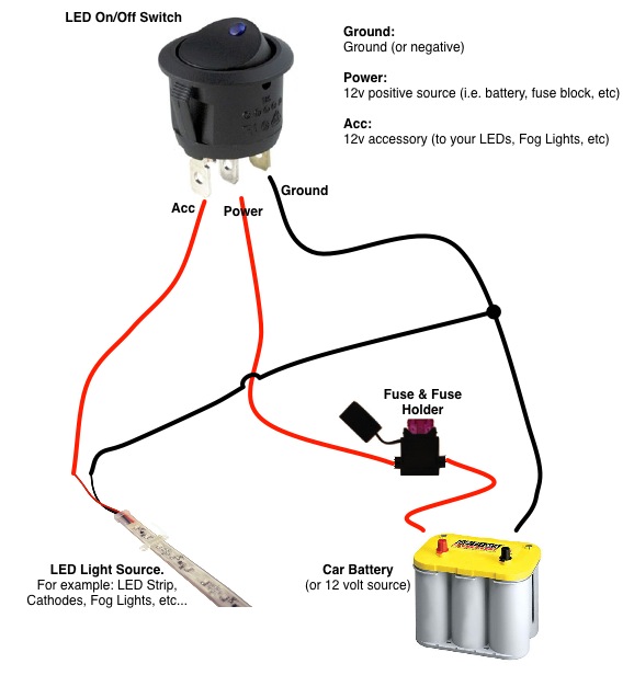
I found this diagram on Google. Hopefully this helps.
If someone kind and knowledgeable would be able to sketch out a schematic that could help, cause I'm still not understanding.
I think this is what I was trying to do
I forgot to label it, but the line coming off the LED going to ground is labelled "Earth"
Is this correct?
I think this is what I was trying to do
I forgot to label it, but the line coming off the LED going to ground is labelled "Earth"
Is this correct?
Thats the thread I was going off of. If helped a lot, and if I had just gone with a standard switch all would have gone smoothly, but that thread is detailed up until the switch, it just says "Hook it up" and "Attach 12v for LED"
So I understand that the Supply and Load wires are for the switch, and Earth is supposed to be ground? Or should I be connecting "Earth" to 12v?
So I understand that the Supply and Load wires are for the switch, and Earth is supposed to be ground? Or should I be connecting "Earth" to 12v?
I think I figured it out. I connected "Supply" to the b/w wire coming from the circuit opening, and connected "Earth" to the b/w wire going to the harness, leaving "Load" disconnected. Do you see any problems with additional resistance going to the fuel pump relay?
Trending Topics
Sharingan, legendary advice. LED switches are only in use everywhere. If you have a reason why a 30a switch wouldn't work I'd love to hear it, otherwise I'm looking for ways to make this work, not reasons to give up.


Without knowing if there is an internal current limiting resistor I can't be certain. But since you don't show one in your schematic, I'm assuming there isn't one.
Problem about the LED blowing is due to there being too much current running through that LED. You'll need a current limiting resistor in series with it to keep the LED from blowing. There are some web calculators that will do the calculation of the resistor value for you, but you will need the LED current rating and forward voltage information (although this is typically 1.8 to 3.3 volts).
Sounds like you figured out the switch configuration, 15A fuse blowing problem though. If you don't care about the light then you should be good to go! The circuit the way you have it drawn should work.
Feel free to PM me if you have questions.
Last edited by kencunm; Jan 27, 2012 at 09:52 AM. Reason: current value change

Thread
Thread Starter
Forum
Replies
Last Post
alphawolff
1st Generation Specific (1979-1985)
17
Nov 17, 2015 05:57 PM
armans
3rd Generation Specific (1993-2002)
5
Aug 15, 2015 09:08 PM