
FMIC question


Thread Starter
Senior Member
Joined: May 2005
Posts: 639
Likes: 0
From: MA
FMIC question
I was looking at my car yesterday and I will be installing an FMIC. The question I have is is it possible to install 2.5 inch piping around the battery and coil without having to relocate the battery?
A lot of people I noticed relocate the battery I was hoping to be able to just somehow squeeze the piping past the battery and coil if that was at all possible? Does anyone have any pics of this done?
Also what tends to be a good size FMIC for a t60 running around 10-12psi... I dont want it to be too massive to the point where it blocks my rad from getting air. I have the gp sports front
Thread Starter
Senior Member
Joined: May 2005
Posts: 639
Likes: 0
From: MA
well I was hoping for a custom fmic setup... I was on ebay and noticed you can get a core for 200 shipped and then piping clamps and silicon connectors for another 150 or so so about 400 for a complete setup compared to the 900 greddy anyone have any pics of this done?

Rotary Freak
Joined: Apr 2003
Posts: 2,702
Likes: 1
From: DC Area
its not going to as easy as pipes clamps and connectors. You will need some bends welded together that are not off the shelf stuff. If you can weld yourself then go for it. If you have to pay some to do all this work then its worth the money for the greddy. I cannot weld aluminum so I just picked up the greddy and was good to go.
And yes you will probably get alot of people pics on here of the "200" dollar setup they fabed up in their backyard and I tell you it looks like you fabed it up in their backyard using junk yard intercoolers, spray paint, and couplers from home depots plumbing department.
And if you do a search it has been covered a few times on this topic once you buy the aluminum straits, bends, couplers, clamps and the intercooler you are right at about 900 bucks.
and yes bring on the pics of the ghetto fab home intercooler kits!
Thread Starter
Senior Member
Joined: May 2005
Posts: 639
Likes: 0
From: MA
I am not looking for a show car finish here I am looking for something that works and is functional... I dont see how it could cost 400+ dollars to get someone to just weld up the pipes for you... cutting them is easy and then marking them where they need to be welded after you do that you bring the pipes to an exhaust shop or just some welder and have him weld them up for you quickly... i am going to do all the measurements and cutting myself... i was just curious how easy it would be to route it around the battery...
Anyone with pics please bring them on
Anyone with pics please bring them on
Trending Topics


I have injector envy!
Joined: Feb 2004
Posts: 1,106
Likes: 6
From: virginia
you call that ghetto...looks nice to me.
I'm going to rout my pipes straight back from a rear exiting intercooler end tank, they will go around the radiator and straight to the turbo and the throttle body, I figure its the shortest and straightest path to take.
I'm going to rout my pipes straight back from a rear exiting intercooler end tank, they will go around the radiator and straight to the turbo and the throttle body, I figure its the shortest and straightest path to take.

Originally Posted by need-a-t2
My ghetto intercooler pipes. I relocated the battery tho. cost me about $350 all together


Rotary Enthusiast
Joined: Sep 2001
Posts: 1,417
Likes: 0
From: Pittsburgh Pa
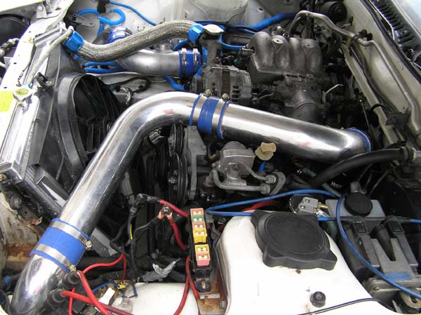
Originally Posted by MARTIN
everything stock even fogllights.... no relocation...

thats got to be a pain in the ***
Passing life by
Joined: Feb 2005
Posts: 4,028
Likes: 2
From: Scotland, USA
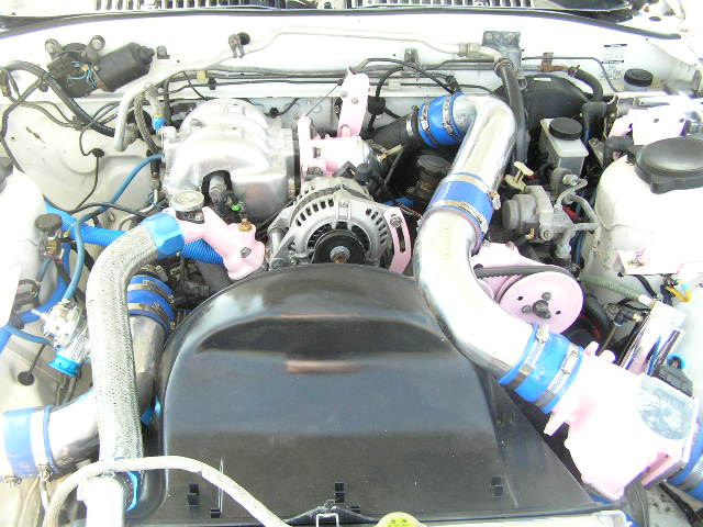
Here is my setup. I kept AC and PS but I relocated my BATT. I also ran 3in piping so thats alot harder then 2.5. I ran 3in b/c I was planing ahead but now I will not be keeping PS and want a new rought. Yes I weld aluminum and did it myself. Cost me like 700 for it with BOV. I did have to relocate my batt. I ran out of pipe and had to purchas 2 90o bends from an exhaust shop and cut weld them together. I did this under the driver side section where you dont see it. Not shown in pics.

Last edited by iceblue; Jan 12, 2006 at 07:10 PM.
BOOSTED Vert
Joined: Sep 2002
Posts: 2,307
Likes: 0
From: Miami
Originally Posted by Pinfield357
do you have to remove your intercooler pipeing to remove the battery?
thats got to be a pain in the ***
thats got to be a pain in the ***
BTW that is 2.75" piping... I mentioned 2.5 in other threads because Im so used to that number being associated with IC piping..
Last edited by MARTIN; Jan 13, 2006 at 02:05 AM.
Thread Starter
Senior Member
Joined: May 2005
Posts: 639
Likes: 0
From: MA
martin did you use a greddy tb adapter or anything.... i hope you dont mind but i would like to pretty much steal ur exact pipe layout... if you have more pics that would be awesome if so could you send them to xbladr@comcast.net? Thanks

1 miracle from sainthood
Joined: Dec 2004
Posts: 455
Likes: 0
From: Massachusetts / Osaka Japan
Originally Posted by iceblue
do you have any problems with the AFM slamming shut when the BOV lets go, then it would give the ECU some odd information...
I am very confused by that. I've never seen an AFM on the pressure side.
Thank you for your help,
TR
King of the Loop
Joined: Apr 2004
Posts: 2,620
Likes: 1
From: brooklyn, New York
Originally Posted by takahashiRyosukeFC3S
Umm, does that setup work well? I noticed the AFM is on the pressure side of the turbo, not the initial intake... also the BOV is closer to the turbo than the TB...
do you have any problems with the AFM slamming shut when the BOV lets go, then it would give the ECU some odd information...
I am very confused by that. I've never seen an AFM on the pressure side.
Thank you for your help,
TR
do you have any problems with the AFM slamming shut when the BOV lets go, then it would give the ECU some odd information...
I am very confused by that. I've never seen an AFM on the pressure side.
Thank you for your help,
TR
Passing life by
Joined: Feb 2005
Posts: 4,028
Likes: 2
From: Scotland, USA
Originally Posted by takahashiRyosukeFC3S
Umm, does that setup work well? I noticed the AFM is on the pressure side of the turbo, not the initial intake... also the BOV is closer to the turbo than the TB...
do you have any problems with the AFM slamming shut when the BOV lets go, then it would give the ECU some odd information...
I am very confused by that. I've never seen an AFM on the pressure side.
Thank you for your help,
TR
do you have any problems with the AFM slamming shut when the BOV lets go, then it would give the ECU some odd information...
I am very confused by that. I've never seen an AFM on the pressure side.
Thank you for your help,
TR
1. A stock setup with AFM placement as VACC is to re-circulate and not vent the BOV. The placement of the BOV is really irrelevant they both have their ups and down on what side of the IC they are on. Close to the TB really means nothing for how it works. With this setup it aloud me to vent properly b/c the air being vented is before it is calculated by the AFM. I also noticed less rich shots between ***** and a smoother running car. Over all I am exceptionally pleased with this setup. Boost section of VACC section matters not it is all the same amount of air. The AFM slamming shut is what I want.

Thread
Thread Starter
Forum
Replies
Last Post
Adaptronic S5 Turbo PNP Unit questions
_Tones_
Adaptronic Engine Mgmt - AUS
10
May 25, 2021 05:37 AM
Nosferatu
2nd Generation Specific (1986-1992)
7
Sep 5, 2015 02:13 PM