
FD Twins on FC


To use an Rtek you will need to build a custom intake splitter that will go after the AFM to each turbo inlet. The FD doesn't have an AFM. For the charge relief valve you will have to figure out how to recirculate that back to the intake unless you want to hear a hissing sound all the time.
The sequential turbo control can be done simply. Four 3-way solenoids will work. Here's how the stock FD solenoids are set up:
They're really not much different from FC emissions solenoids, so you could probably modify an FC rat's nest if you wanted to. There are two turbo control solenoids though, one for vacuum and one for pressure. Otherwise you can buy some MAC 3-way solenoids with threaded fittings that you can configure however you want. It is part # # 35A-AAA-DDBA-1BA . This is the same part as the AEM boost control solenoid.
For control you need one window switch for the charge relief, which will be on from about 2500-4000 rpm. Then you can use the RPM activation of the Rtek to switch the charge control solenoid and the two turbo control solenoids. Charge control and turbo control solenoids could be switched at about 4000.
Precontrol and wastegate could be controlled with an aftermarket electronic boost controller or with some MBC's if you want to go that route.
Exactly as i planned. except the values will probably change bit b/c of the higher cr rotors, i will find the optimal rpm for transition on a dyno. thats why i will be leaving them adjustable. thanks for the extra info this will certianly be benefitial.
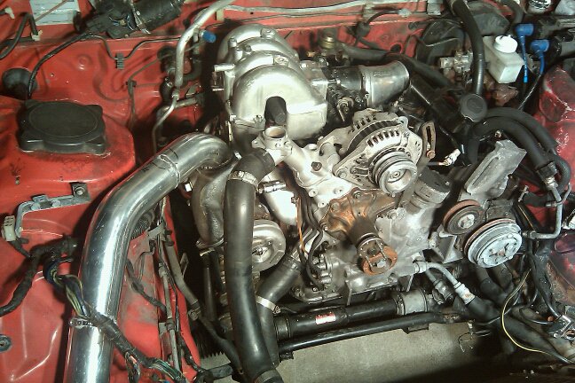
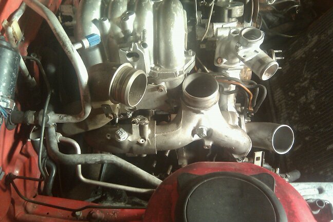
The FD twins and manifold will not fit with a FC LIM without making a spacer to push the turbos out away from the block.
The FD LIM sits much higher on the side of the engine, it can not just be bolted to a TII block, without considerable modifications and even then the intake runners are at drastically different angles.
FC vs FD intermediates
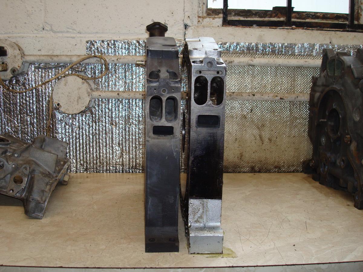
You can see in this picture just how close the twins are the FD LIM
The FD LIM sits much higher on the side of the engine, it can not just be bolted to a TII block, without considerable modifications and even then the intake runners are at drastically different angles.
FC vs FD intermediates
You can see in this picture just how close the twins are the FD LIM

I've tried to mount a set of REW twins on a 13BT in the passed. They wouldn't clear without a spacer. Then with the spacer, there was less than 2" inbetween the exhaust flange and the frame of the car to try and get creative with a downpipe. You can probably grind your LIM all to hell and possibly have it fit with a paper thin LIM but I don't think it would hold up very long.
He's got a Motec M820, so the outputs needed to be able to run the twins sequential are available. Using an Rtek and a "custom made twin turbo controller" will not get results like his set up.
Get a Motec, a 13BRE or 13BREW installed, then go for the twin sequential setup like Titanium has.
Originally Posted by lastphaseofthis
i want what you have. except with an rtek and a custom made twin turbo controller. even it's all boost sensors/rpm switches and relays, and ghetto fabulous. i wanna see 5 psi at 2000. or close to it. 9.4, or maybe 9.7 will be the ticket.
Get a Motec, a 13BRE or 13BREW installed, then go for the twin sequential setup like Titanium has.
It doesn't have to be a Motec. At bare minimum you need 1 means of switching at a fixed rpm (main transition point for charge control and turbo control) and 1 means of switching at an rpm window range (for charge relief). Boost control is all up to your preferences.
awe hell, **** it then, thanks banzai, that shows me Exactly what i need to know, it's been a while since the last time i worked on an FD, and i never compared the 13bt to the REW side to side.
Yes, arghx, you really don't need a whole lot to run them sequential, as was cover'd above. my main focus was fitting, which i now see i WILL need to space it.
when i am pulling the motor in the next coming days, im going to check to see how far it needs to come out, and then how much clearnce i have to the frame of the car.
Thanks yall.( I am in Alabama, yall is a word here)
Well I'll be damned. More pics? More details on the setup? What engine management? Sequential or non sequential? Did you have any fitment issues with the twins, the intake, the downpipe?
I will see if I can find more pics.
He is using S4 turbo electronics with 550 injectors. Since this is his daily and he needed is ASAP we had to go the fastest and easiest rout. So it is running non sequential and the AFM is setup as blow through.
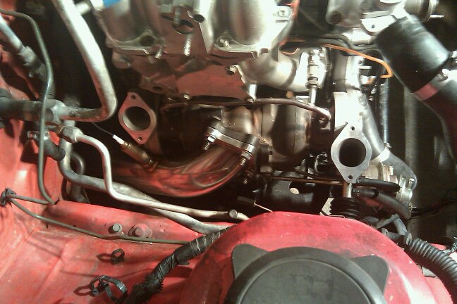
To clear the block we used a header flange as a spacer and about 10 mins with a dremel to make the rear compressor clear the the rear secondary runner. For the intake he using two cone filters. The down pipe is an e-bay special that bolted on like stock. We even got the FD midpipe to mate to a Racing Beat y-pipe with just two cuts and rewelding.
He is using S4 turbo electronics with 550 injectors. Since this is his daily and he needed is ASAP we had to go the fastest and easiest rout. So it is running non sequential and the AFM is setup as blow through.
To clear the block we used a header flange as a spacer and about 10 mins with a dremel to make the rear compressor clear the the rear secondary runner. For the intake he using two cone filters. The down pipe is an e-bay special that bolted on like stock. We even got the FD midpipe to mate to a Racing Beat y-pipe with just two cuts and rewelding.
Joined: Dec 2001
Posts: 10,630
Likes: 3
From: NY, MA, MI, OR, TX, and now LA or AZ!
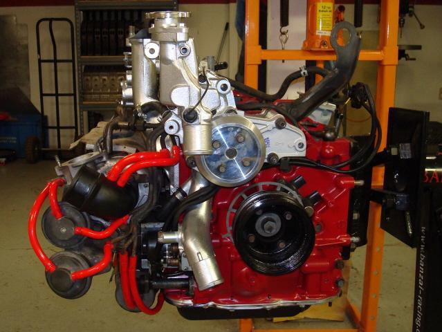
It's cool to see I'm not the only one doing this. I had a complete REW longblock, so the 'cost' factor was right to putting it on my GTUs. I use a modified REW intake setup though rather than the TII manifolds. Also, sequential with a MS-II.
How is the blow-through configuration working out? You're going to need to keep it at spring pressure for a while until you get the fuel and engine management worked out. How did you run the oil and coolant lines?
Joined: May 2006
Posts: 3,881
Likes: 3
From: Jacksonville, Tampa & Tallahassee
All of it, lol.
But seriously; a pic of the finished product would be nice, how does the blow through afm setup work? How does it perform? Hp? spool? Routing of coolant/oil lines? ECU tricks/tips.....stuff like that. Feel free to send a PM if it seems like I'm the only one who cares
But seriously; a pic of the finished product would be nice, how does the blow through afm setup work? How does it perform? Hp? spool? Routing of coolant/oil lines? ECU tricks/tips.....stuff like that. Feel free to send a PM if it seems like I'm the only one who cares
Joined: Dec 2001
Posts: 10,630
Likes: 3
From: NY, MA, MI, OR, TX, and now LA or AZ!
I'd imagine spool would be slightly worse than a stock TII in non-seq, blow-through AFM simply means the AFM is mounted in the IC piping, rather than in the inlet duct. This is commonly done with S5 AFM's as they're already somewhat in the shape to accommodate this.
HP is relative to boost, engine, tune, and every other factor, so that'd be hard to say. I'd imagine maybe 200whp or so in the configuration posted above would be reasonable.
Coolant lines can be hijacked from the inlet/outlet that runs through the BAC/thermowax, that's the common source for any 6 port turbo. Oil is more random, I use a greddy oil block that has a -4AN adapter, and feed my oil from this pedistal. For returns, I T'd both drains together and ran it to the front cover where the stock drain is.
Aftermarket ECU is definitely preferred. Unless you have all of the parts laying around to make this work, going single would be preferred unless you're aiming to keep sequential like I did. In that case you just need an ECU with a few RPM outputs, if you can use logic in these outputs that's even better, such as if boost < 5psi and RPM > 4000rpm, then run sequential, or so forth.
Joined: May 2006
Posts: 3,881
Likes: 3
From: Jacksonville, Tampa & Tallahassee
I know what a blowthrough setup is, I was more interested in what problems (if any) were encountered running it. Thanks for the info.
Agreed, running non-sequential is kind of foolish. I have an rtek currently (1 rpm outupt) I'm sure there's a way to rig up a crude sequential setup with some solenoids and relays and such. But I'm mainly researching for a future build. Care to share what ecu you're using (unless its a motech lol) and how you have the sequential controls rigged up?
Agreed, running non-sequential is kind of foolish. I have an rtek currently (1 rpm outupt) I'm sure there's a way to rig up a crude sequential setup with some solenoids and relays and such. But I'm mainly researching for a future build. Care to share what ecu you're using (unless its a motech lol) and how you have the sequential controls rigged up?
Joined: Dec 2001
Posts: 10,630
Likes: 3
From: NY, MA, MI, OR, TX, and now LA or AZ!
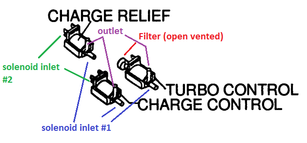
I'm using a MS-II. My vacuum routing follows this diagram (I'm using 2 outputs, one for turbo control solenoids, and the other for charge relief). I've got 3 solenoids controlling the entire operation, I've condensed the two charge solenoids into one single solenoid, the turbo control uses two ran off the same output. I've got the turbo controls set at 4000, and the charge relief follows shortly after at 4200.


Thread
Thread Starter
Forum
Replies
Last Post
Turblown
Vendor Classifieds
12
Oct 17, 2020 03:25 PM