
Electric 6 port activation (alternate wiring? Electric heads I need help..)

Thread Starter
Born-again Rotor-Head
Joined: Aug 2007
Posts: 214
Likes: 0
From: georgia
Electric 6 port activation (alternate wiring? Electric heads I need help..)
Ok, I have read how to use the rpm switch to activate your 12v air pump at the proper RPM range, but the $150 to waste on a single function i.e. operating your 6PI system seems, well, wasteful (besides, I may need to spend that $150 on an RPM switch for my Triumph TR7 slant 4/V8 swap..). So I think I may have come up with a less expensive way to get the 12v pump to function but I cannot get anyone to give me any feedback, so anyone with any expertise in electronics AND rx7s maybe you can tell me if this will work without frying my ECU or making my injectors stick open? Thanks!
option 1
option 2
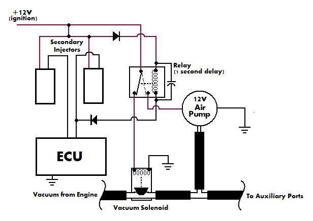
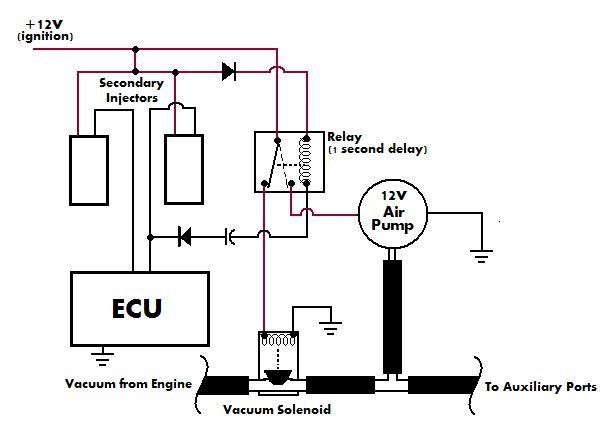
BTW, note the capacitor is used to delay the relay's disengagement for long enough that the next pulse from the injector (or ecu) comes before the circuit has opened, the positioning is what I am unsure of as well as whether it is ecu/injector friendly to wire this in this manner..I am attempting to make my own 12v off-delay relay that is ground-sensitive as it will always have power..
option 1
option 2
BTW, note the capacitor is used to delay the relay's disengagement for long enough that the next pulse from the injector (or ecu) comes before the circuit has opened, the positioning is what I am unsure of as well as whether it is ecu/injector friendly to wire this in this manner..I am attempting to make my own 12v off-delay relay that is ground-sensitive as it will always have power..
Thread Starter
Born-again Rotor-Head
Joined: Aug 2007
Posts: 214
Likes: 0
From: georgia
I had thought of using a transistor as well, though I thought once you put a the base to the transistor the transistor stays 'ON' so long as power continues passing from the collector to the emitter? Therefore shutting the power OFF once it was triggered would be another circuit or component..
And as for the relay "pulsing" with the ECU's ground signal, the other reason for the capacitor, it would slowly discharge and iron out the wrinkles..as well as slowing the relay's "off" time, i.e off-delay
I found some info about it on an audio-related forum on aaron cakes website
And as for the relay "pulsing" with the ECU's ground signal, the other reason for the capacitor, it would slowly discharge and iron out the wrinkles..as well as slowing the relay's "off" time, i.e off-delay
I found some info about it on an audio-related forum on aaron cakes website
Trending Topics
Thread Starter
Born-again Rotor-Head
Joined: Aug 2007
Posts: 214
Likes: 0
From: georgia
Former Moderator. RIP Icemark.
Joined: Apr 2001
Posts: 25,896
Likes: 24
From: Rohnert Park CA
I had thought of using a transistor as well, though I thought once you put a the base to the transistor the transistor stays 'ON' so long as power continues passing from the collector to the emitter? Therefore shutting the power OFF once it was triggered would be another circuit or component..
And as for the relay "pulsing" with the ECU's ground signal, the other reason for the capacitor, it would slowly discharge and iron out the wrinkles..as well as slowing the relay's "off" time, i.e off-delay
I found some info about it on an audio-related forum on aaron cakes website
And as for the relay "pulsing" with the ECU's ground signal, the other reason for the capacitor, it would slowly discharge and iron out the wrinkles..as well as slowing the relay's "off" time, i.e off-delay
I found some info about it on an audio-related forum on aaron cakes website
Joined: Feb 2001
Posts: 29,798
Likes: 128
From: London, Ontario, Canada
If you want to do this safely, it's easy.
Parallel an optoisolator with one of the secondary injectors. Use appropriate resistor value on LED side of isolator. Now drive a 2N3904 transistor from the output side of the opto with a low value capacitor at the base (10uF). The transistor switches the relay.
If someone really wants a schematic I can draw one but won't get around to it for a few days.

Full Member
Joined: Oct 2007
Posts: 77
Likes: 0
From: Phoenix AZ
If you want to do this safely, it's easy.
Parallel an optoisolator with one of the secondary injectors. Use appropriate resistor value on LED side of isolator. Now drive a 2N3904 transistor from the output side of the opto with a low value capacitor at the base (10uF). The transistor switches the relay.
If someone really wants a schematic I can draw one but won't get around to it for a few days.
Parallel an optoisolator with one of the secondary injectors. Use appropriate resistor value on LED side of isolator. Now drive a 2N3904 transistor from the output side of the opto with a low value capacitor at the base (10uF). The transistor switches the relay.
If someone really wants a schematic I can draw one but won't get around to it for a few days.
I miss Austin
Joined: Nov 2007
Posts: 84
Likes: 0
From: Santa Fe, NM
Joined: Oct 2002
Posts: 674
Likes: 1
From: California & Florida
I added a VDI to my S4 so I had to do both 5th/6th ports and the VDI at different times. I ended up going from my *** to my elbow with 2 rpm swithes, two solenoids and an air compressor + mini-regulator and door-jamb switches with leds on everything & a boost gauge & a-pillar mount. It works perfectly though. And is adjustable and has full indicator lights... check out my Success!! thread.
Ramses666
Ramses666
Thread Starter
Born-again Rotor-Head
Joined: Aug 2007
Posts: 214
Likes: 0
From: georgia
aaron cake, that would be awesome if you could do that on your own time- like I said I am getting the headers this weekend and mufflers soon after that, so sometime in the next week or two I was hoping to get some feedback that I could start wiring up. If there's anything I could do in return just let me know. Thanks!
Instead of buying a switch you can build 2 of them for about $30
https://www.rx7club.com/2nd-generation-specific-1986-1992-17/diy-rpm-switch-complete-pics-745906/
https://www.rx7club.com/2nd-generation-specific-1986-1992-17/diy-rpm-switch-complete-pics-745906/


What is the point of this if it's not adjustable based on rpm? Why not get an Rtek 2.1 which has a built-in rpm switch? You need to be able to adjust the activation point precisely so you can tune it for the best power and torque curve. I applaud you trying to come up with your own custom solution, but it's still a cheap bastard mod (and I'm not 100% against cheap bastard mods) that mostly importantly isn't as good as the real thing.
Last edited by arghx; Apr 28, 2008 at 04:04 PM.
Thread Starter
Born-again Rotor-Head
Joined: Aug 2007
Posts: 214
Likes: 0
From: georgia
No, I don't need a switch that is variable in its input- seeing as how the 6pi is supposed to open at 3800-4000 rpm from everywhere I read, that is a 200 RPM window, that is arbitrary when you are revving your engine quickly, 200 RPM increase is -1 second. I am not trying to put it on the track (just yet anyhow) just trying to get my 6pi functioning independently of backpressure so I can mod my exhaust line without worry..as an aside I got my RB collected header bolted up, I made a 3.5 inch extension so I can bolt the header straight up to my stock cat for now, seems to be an improvement over stock...and while bolting it up I jiggled my 6pi actuators and I think I got them working with this setup

Thread
Thread Starter
Forum
Replies
Last Post
sherff
Adaptronic Engine Mgmt - AUS
9
Feb 24, 2019 12:09 PM
The Shaolin
2nd Generation Specific (1986-1992)
9
Sep 14, 2015 07:50 PM