
DIY RPM Switch Complete with pics

Thread Starter
Joined: Aug 2007
Posts: 273
Likes: 0
From: Muskegon, MI
DIY RPM Switch Complete with pics
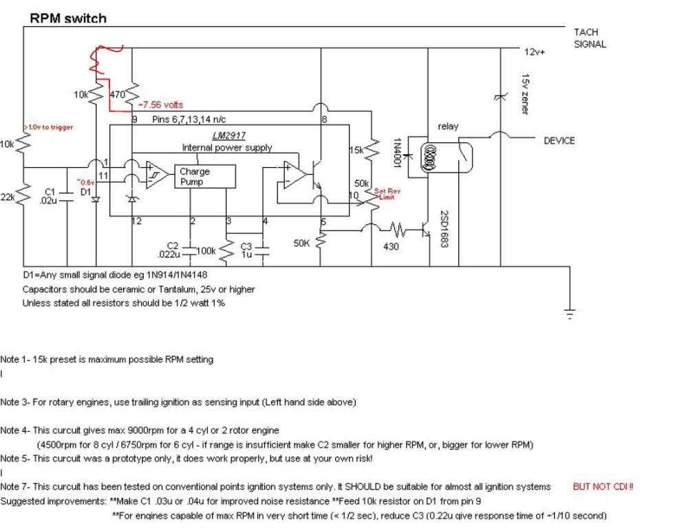
So, I'm building a S5 Street port for my FB and wanted to remove all of the emissions but retain the aux ports and VDI. Two rpm switches would be needed to run them for about $55 each you can get them on Summit. I decided to build mine. I found the circuit diagram here:
https://www.rx7club.com/showthread.p...DIY+rpm+switch
A friend and I drew it up in a PCB cad program and here is our work.
The .pdf of the PCB layout is attached.
The basic idea is that you take the layout and print it onto glossy laser printer paper and then iron the image onto the copper clad PCB board. Soak the whole thing in water until the paper turns to mush. Carefully rub the paper off leaving the toner behind. At this step the board will need to be soaked in ferric chloride. Anywhere there is no toner the copper will be eaten away, leaving the traces. Once only the traces are left, rinse it throughly with water and scrub off the toner with a Brillo pad.
Here is the board we made:
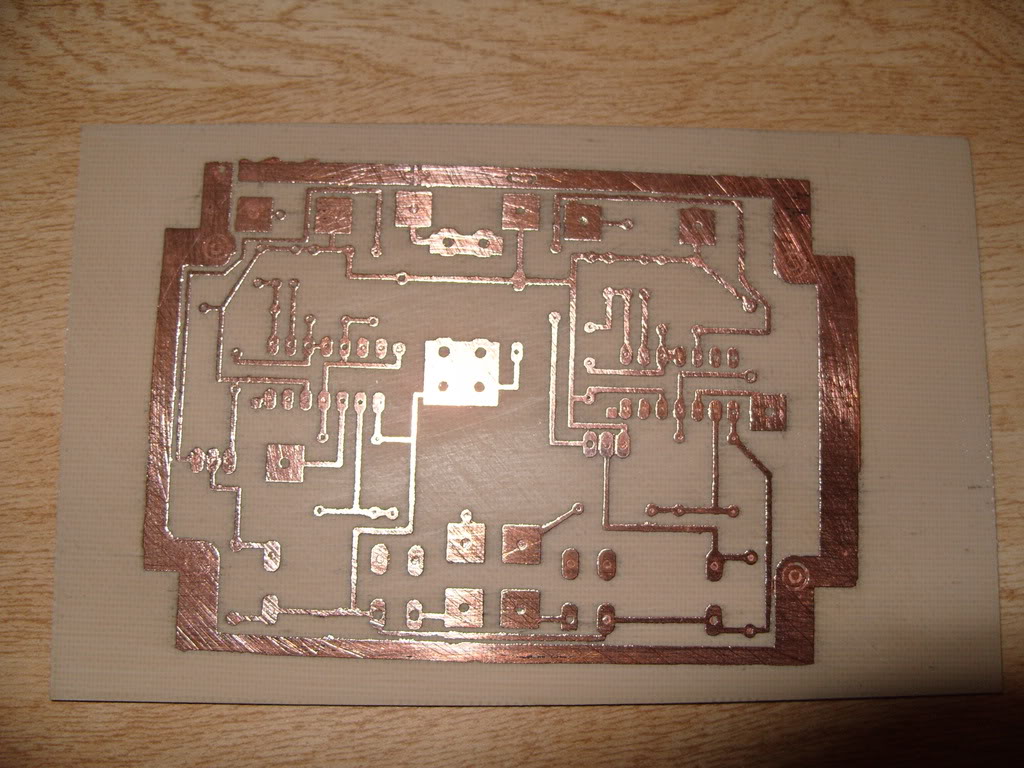
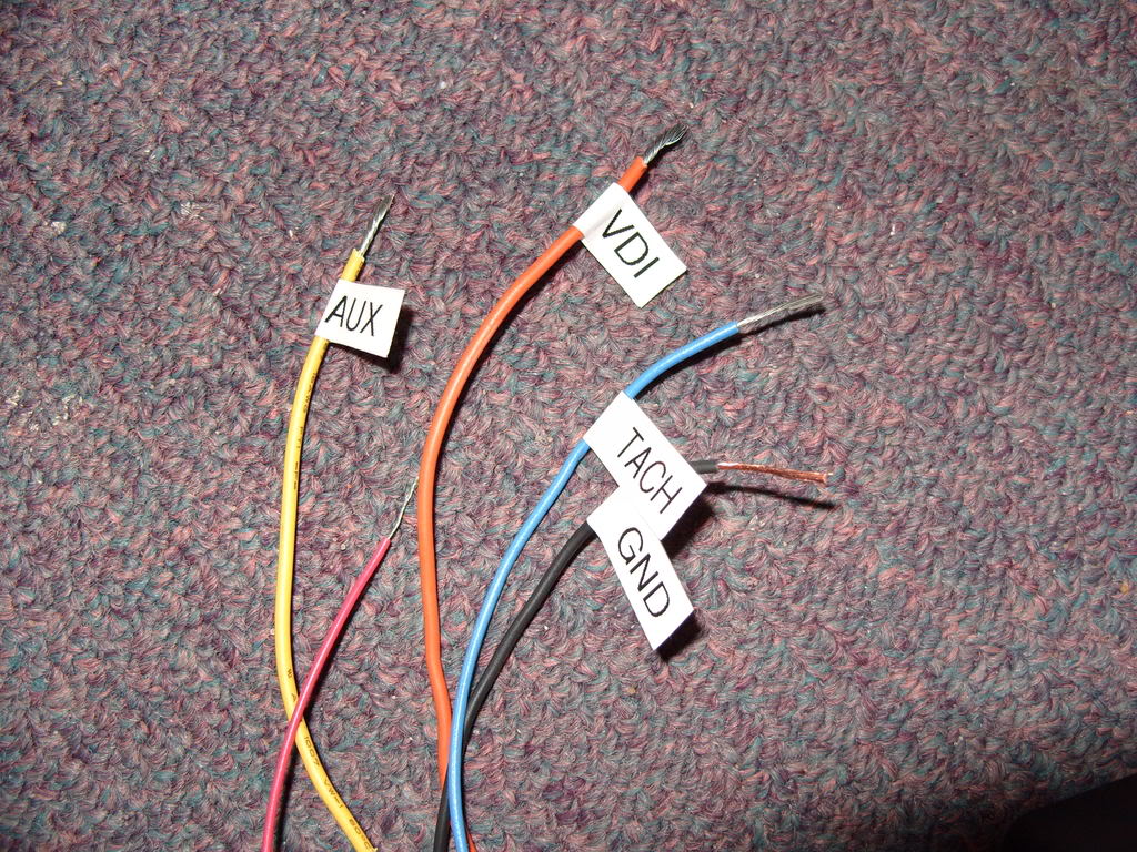
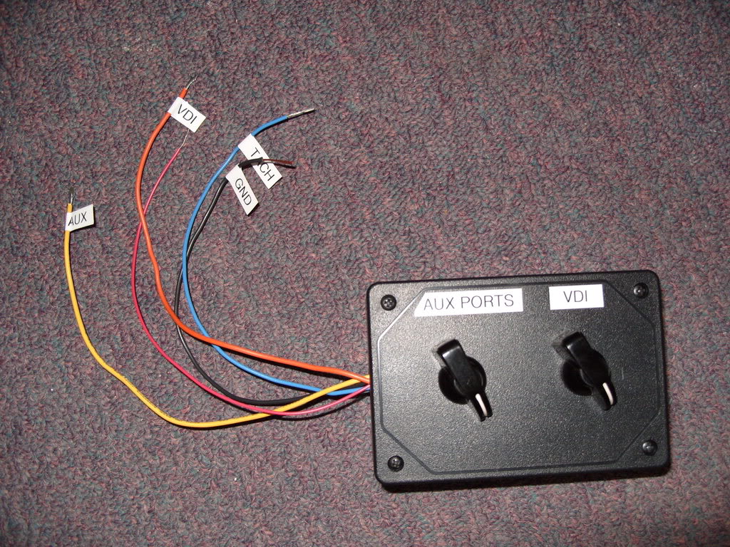
This board is made to have two switches. One for the Aux ports and another for the VDI.
Below is the part list of the components I ordered from Mouser.com
<wbr>------------------------------<wbr>---------------------------------------------
ORDERED STOCK NUMBER PRICE
------------------------------<wbr>------------------------------<wbr>---------------
1 563-CU-3281 7.200 7.20
4 273-10K-RC 0.100 0.40
2 273-430-RC 0.100 0.20
2 273-15K-RC 0.100 0.20
2 273-51K-RC 0.100 0.20
2 526-NTE995 3.750 7.50
2 512-KSD1691GS 0.530 1.06
2 273-22K-RC 0.100 0.20
2 273-470-RC 0.100 0.20
2 660-MF1/2CC1003F 0.140 0.28
2 80-C317C223K5R 0.160 0.32
2 21RX421-RC 0.130 0.26
2 810-FK24X7R1H224K 0.180 0.36
2 512-1N4148TA 0.030 0.06
2 512-1N4001 0.050 0.10
1 512-1N6004B 0.050 0.05
2 677-PCI-212DMH 1.360 2.72
2 31VQ405-F 1.400 2.80
1 693-0031.8231 0.930 0.93
The total came to $31.28 with shipping.
After that it pretty much comes down to soldering in the components.
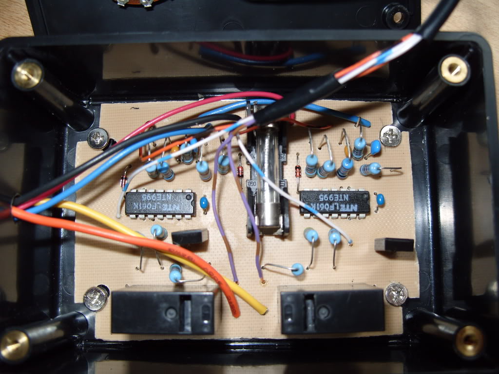
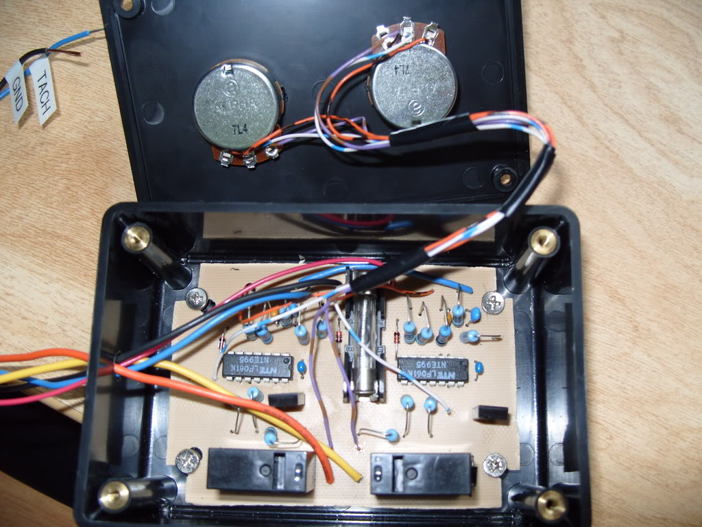
The ***** were an extra touch added later. I don't know if they will stay or not.
https://www.rx7club.com/showthread.p...DIY+rpm+switch
A friend and I drew it up in a PCB cad program and here is our work.
The .pdf of the PCB layout is attached.
The basic idea is that you take the layout and print it onto glossy laser printer paper and then iron the image onto the copper clad PCB board. Soak the whole thing in water until the paper turns to mush. Carefully rub the paper off leaving the toner behind. At this step the board will need to be soaked in ferric chloride. Anywhere there is no toner the copper will be eaten away, leaving the traces. Once only the traces are left, rinse it throughly with water and scrub off the toner with a Brillo pad.
Here is the board we made:
This board is made to have two switches. One for the Aux ports and another for the VDI.
Below is the part list of the components I ordered from Mouser.com
<wbr>------------------------------<wbr>---------------------------------------------
ORDERED STOCK NUMBER PRICE
------------------------------<wbr>------------------------------<wbr>---------------
1 563-CU-3281 7.200 7.20
4 273-10K-RC 0.100 0.40
2 273-430-RC 0.100 0.20
2 273-15K-RC 0.100 0.20
2 273-51K-RC 0.100 0.20
2 526-NTE995 3.750 7.50
2 512-KSD1691GS 0.530 1.06
2 273-22K-RC 0.100 0.20
2 273-470-RC 0.100 0.20
2 660-MF1/2CC1003F 0.140 0.28
2 80-C317C223K5R 0.160 0.32
2 21RX421-RC 0.130 0.26
2 810-FK24X7R1H224K 0.180 0.36
2 512-1N4148TA 0.030 0.06
2 512-1N4001 0.050 0.10
1 512-1N6004B 0.050 0.05
2 677-PCI-212DMH 1.360 2.72
2 31VQ405-F 1.400 2.80
1 693-0031.8231 0.930 0.93
The total came to $31.28 with shipping.
After that it pretty much comes down to soldering in the components.
The ***** were an extra touch added later. I don't know if they will stay or not.
Thread Starter
Joined: Aug 2007
Posts: 273
Likes: 0
From: Muskegon, MI
Notes
Just a note for use that I didn't realize until I started testing. The RPM of the car is not the triggering frequency of the switch.
1000 rpm = 33.3 Hz
2000 rpm = 66.6 Hz
3000 rpm = 100 Hz
4000 rpm = 133.3 Hz
5000 rpm = 166.6 Hz
6000 rpm = 200 Hz
7000 rpm = 233.3 Hz
Also another note for testing, make sure the signal amplitude is > 10V.
I also noticed that the diagram I posted does not include the labels for the components. I'll have to post that when I get a chance.
 WTF man? You're one advanced bastard! I wish I knew what was going on.


Trending Topics
Thread Starter
Joined: Aug 2007
Posts: 273
Likes: 0
From: Muskegon, MI
Yeah. Everything seems to work great. I did a few hours worth of testing with a function generator, amplifier and power supply. I had to test it in the lab because I'm at school and my car is about 500 miles away. Once I realized the frequencies were wrong testing went much easier. Only other thing I've changed was the connections to the pots. I fixed them so that clockwise was increasing instead of decreasing. Simple fix. All in all, I probably have about 5 hours into it and ~$30.
I'd like to see something like a pre-etched board for sale here, or maybe even one with components already soldered, so I'm staying close to the subject. The archive is excellent, but it is far from plug and play.
Aaron may be referring to a thread I made recently, which was for a single load control based on RPM (I edited the wiring diagram above, based on the diagram in the archives (NOT by me) linked in post #2.
I haven't tested mine yet, and honestly, am a little apprehensive, because I used 5% tolerance resistors, and used some polymer capacitors - I hope it'll work. My first version is a maze of wires, and the other day I tried a PCB layout program for the first time. I'm not happy with the layout I created, but etched it onto a board as mentioned above, just for kicks. I can solder fairly well, but am only a noob at this.
Would it be too much to have you post the PCB program link and trace file for the list, for those willing to etch their own board? If you don't want to share this info, I'll completely understand, but would at least encourage you to produce etched boards for a reasonable price (~$10).
Aaron and others - what are the prices on getting a bunch of boards made professionally. If no one is interested, maybe someone else would help the list and themselves. Don't have the time nor (honestly) the knowledge, for now.
Edit: I'll post a pic. of the maze I created if anyone's interested.
Last edited by pfsantos; Apr 7, 2008 at 03:16 PM.


Junior Member
Joined: Jul 2007
Posts: 36
Likes: 1
From: Florida
printed board
I use to do the pc boaRDS WHEN i WAS YOung with nail polish and nitric acid ,Now Im retaired ,can you make some pc boards my eyw vision is bad,you could use multrim potencimeters to do the adjustments more precise.
Thanks
Thanks
Thread Starter
Joined: Aug 2007
Posts: 273
Likes: 0
From: Muskegon, MI
pfsantos - I don't know if I'd want to go as far as selling pre-made boards, simply because I am picky and don't want to get into the hassle of producing these for others. I have seen too many threads of people selling things on this forum where customers are upset about time delay or quality.
The PCB program was a non-freeware, CAD type software available on the lab computers here at school, so I can't give you the program. I did include the trace file though so that you could just print the .pdf attached to the first post and etch your own board.
To be honest with you this is my first work attempt at etching PCB as well. My friend and mentor was very helpful. Everything we used was very household type stuff aside from the acid.
As for your components, My resistors are 5% tolerance, though I cannot speak to your capacitors, but I do not think that they would be a problem. Do you have a bread board or function generator for testing?
I'd be willing to answer any and all questions I can.
That's alright. I keep a high standard as well and when I find the time will play with the layout some more until I'm happy, probably using yours as a guide. Since mine is for an S4, I only need one RPM switch. Don't have any means of testing, except for a multimeter to check connections, diodes and resistors, etc.
I should go and test my switch, the weather is getting nice and I want to put her on the road soon with working 6PI.
I should go and test my switch, the weather is getting nice and I want to put her on the road soon with working 6PI.
Thread Starter
Joined: Aug 2007
Posts: 273
Likes: 0
From: Muskegon, MI
If you don't have a function generator, you can use the sound card on your computer and a program like Digital Signal Generator.
http://heliso.tripod.com/download/generator/dsg.htm
http://heliso.tripod.com/download/generator/dsg.htm

Well done. I like it.
I'm not trying to be an *** but you know the stock ecu can do this right? Well it can't change the point at which it turns on but that's not beneficial anyways unless the intake manifold is altered in some way that changing the switching rpm would actually be worth it. Like turning VTEC on a Honda on at a lower rpm it just makes less power.
I put a write up on awhile ago with pics and a wiring diagram on how to use an electric air pump two relays and a bit of wire in conjunction with the stock ecu to have everything still work correctly. It was in the naturally aspirated section. I couldn't fine the post though. where did it go?
Like I'm saying I'm not hating or anything. but if your using the stock ecu it can do all this already so there's no point, but if your changing the intake configuration and other such things and retuning the ecu or have a standalone then you sir have provided the electrically inept masses with a perfect solution that is very low cost and applaud that.
I'm gonna go try to find the post hopefully it wasn't discarded since its so simple to do. Not trying to jack you just letting people know what your device is actually needed for.
OK found it I guess I should have just went to my statistics thing and got it the first time
https://www.rx7club.com/showthread.php?t=833418
Well I don't know why the link isn't working but its in the naturally aspirated forum or use my statics thing to view threads started by me and its the one titled "Is anyone using this?" or something to that effect.
Last edited by Skidtron; Jun 16, 2009 at 11:55 AM. Reason: found link
Thread Starter
Joined: Aug 2007
Posts: 273
Likes: 0
From: Muskegon, MI
As to the purpose of this device, I realize that the ECU sends a signal at a specific RPM to open the VDI and the Aux ports, but as you said the timing cannot be changed. Another advantage of this circuit is that I can run much more current though it than the ECU would handle because I was planning on and still may be using electric solenoids for the actuators. At $50 each from Summit, I think $33 for two is good. You don't have to use them for the VDI or aux ports. It could be a shift light and something else.
The part number you are looking at is a zener diode. Mouser still uses that part number as far as I can tell. Perhaps you are entering in the incorrect number. The first number "1" is the quantity you need, "512-1N6004B" is the part number. The .050 and .05 are the prices, the first being the unit price and the second being the total. Since the quantity is one in this case, the numbers are the same.
As to the purpose of this device, I realize that the ECU sends a signal at a specific RPM to open the VDI and the Aux ports, but as you said the timing cannot be changed. Another advantage of this circuit is that I can run much more current though it than the ECU would handle because I was planning on and still may be using electric solenoids for the actuators. At $50 each from Summit, I think $33 for two is good. You don't have to use them for the VDI or aux ports. It could be a shift light and something else.
As to the purpose of this device, I realize that the ECU sends a signal at a specific RPM to open the VDI and the Aux ports, but as you said the timing cannot be changed. Another advantage of this circuit is that I can run much more current though it than the ECU would handle because I was planning on and still may be using electric solenoids for the actuators. At $50 each from Summit, I think $33 for two is good. You don't have to use them for the VDI or aux ports. It could be a shift light and something else.
see
http://mouser.com/Search/ProductDeta...H6keStL%2fo%3d

click things.
http://www.mouser.com/Search/Refine....rd=512-1N6004B
I'm not an electrical engineer so I dunno if the other diodes (512-1N6004B_T50R
and 512-1N6004B_T50A ) will work as a replacement for 512-1N6004B since they are 'different' part numbers, besides I dont want to buy 5000 of them
and yes I am that guy who brings up old posts