Digi7ech's S5 Led Tail conversion

Thread Starter
Joined: Jun 2002
Posts: 4,403
Likes: 4
From: Avondale, Arizona
Digi7ech's S5 Led Tail conversion
I've worked on these for the last few months for my car and a friends and have gotten to a point where I'm some what happy with them.
Me and friends drift so a main goal of these tails is to be able to salvage pieces from them.
Second goal is price. I tried to keep the price down on the production of these things. After talking with some Led guys, cheap was no longer a good thing. China/Ebay 2 prong Led's would be too weak and last for an unknown period of time.
Here is Version one. Cheap.
It is running 16 Chinese Led's per circle and a LM317 voltage regulator at 6.6v. This is good for breaking them every event but bad in long term street car.
They are cheaper to make but won't last as long. The LM317 has to sink a lot of voltage so it will heat up if used constantly.
Pic time:
Outer ring Halo's. These will be running lights. Long term life span is questionable as they see straight car voltage(they run at 12v+).

Here are the Led pucks after etching and about to be assembled.

Here's the Voltage regulator and power board. One for Brakes and one for turn signal.
it also breaks out power and ground for the running lights.

Here's assembled units.

Here they are in a S5 housing all wired up

Front side to give you an idea of how they are laid out

And in Car test video!
[youtube]bqp3Uoq51dI[/youtube]
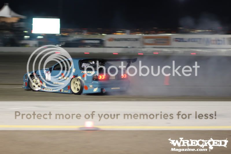
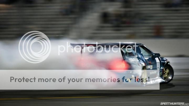
These tails are version one and were a learning experience. They went on George Marstanovic's Formula D car and have already been destroyed at Long Beach. I think I can repair them a bit.
We've also decided to ditch the Running light on the outer turn signal ring. Bringing it back down to the stock 2 brake circles on each tail.

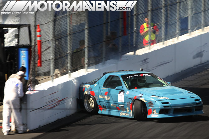
The moment of death for them
Next post will be Version 2!
Me and friends drift so a main goal of these tails is to be able to salvage pieces from them.
Second goal is price. I tried to keep the price down on the production of these things. After talking with some Led guys, cheap was no longer a good thing. China/Ebay 2 prong Led's would be too weak and last for an unknown period of time.
Here is Version one. Cheap.
It is running 16 Chinese Led's per circle and a LM317 voltage regulator at 6.6v. This is good for breaking them every event but bad in long term street car.
They are cheaper to make but won't last as long. The LM317 has to sink a lot of voltage so it will heat up if used constantly.
Pic time:
Outer ring Halo's. These will be running lights. Long term life span is questionable as they see straight car voltage(they run at 12v+).
Here are the Led pucks after etching and about to be assembled.
Here's the Voltage regulator and power board. One for Brakes and one for turn signal.
it also breaks out power and ground for the running lights.
Here's assembled units.
Here they are in a S5 housing all wired up
Front side to give you an idea of how they are laid out
And in Car test video!
[youtube]bqp3Uoq51dI[/youtube]
These tails are version one and were a learning experience. They went on George Marstanovic's Formula D car and have already been destroyed at Long Beach. I think I can repair them a bit.
We've also decided to ditch the Running light on the outer turn signal ring. Bringing it back down to the stock 2 brake circles on each tail.
The moment of death for them
Next post will be Version 2!
Joined: Sep 2005
Posts: 25,581
Likes: 136
From: Smiths Falls.(near Ottawa!.Mapquest IT!)
I've worked on these for the last few months for my car and a friends and have gotten to a point where I'm some what happy with them.
Me and friends drift so a main goal of these tails is to be able to salvage pieces from them.
Second goal is price. I tried to keep the price down on the production of these things. After talking with some Led guys, cheap was no longer a good thing. China/Ebay 2 prong Led's would be too weak and last for an unknown period of time.
Here is Version one. Cheap.
It is running 16 Chinese Led's per circle and a LM317 voltage regulator at 6.6v. This is good for breaking them every event but bad in long term street car.
They are cheaper to make but won't last as long. The LM317 has to sink a lot of voltage so it will heat up if used constantly.
Pic time:
Outer ring Halo's. These will be running lights. Long term life span is questionable as they see straight car voltage(they run at 12v+).
Here are the Led pucks after etching and about to be assembled.
Here's the Voltage regulator and power board. One for Brakes and one for turn signal.
it also breaks out power and ground for the running lights.
Here's assembled units.
Here they are in a S5 housing all wired up
Front side to give you an idea of how they are laid out
And in Car test video!
[youtube]bqp3Uoq51dI[/youtube]
These tails are version one and were a learning experience. They went on George Marstanovic's Formula D car and have already been destroyed at Long Beach. I think I can repair them a bit.
We've also decided to ditch the Running light on the outer turn signal ring. Bringing it back down to the stock 2 brake circles on each tail.
The moment of death for them
Next post will be Version 2!
I like the 2 Guys on the corner of the wall staring at the car scrape the *** end!
..That'll buff out....nope,not this time!


Full Member
Joined: Mar 2007
Posts: 104
Likes: 1
From: AZ
the tails should be 100% salvageable. i only killed off the lenses on the turn signals and one of the halo rings. the other halo ring is there and still works! They are super robust considering i hit the walls 5-6 times at LBC.
Thread Starter
Joined: Jun 2002
Posts: 4,403
Likes: 4
From: Avondale, Arizona
Sorry, XDC was last weekend and completely forgot to post second stuff.
Brian,
Yes I got the idea for layout from the Sakebomb disaster thread. I am not doing Luxeon Star/Cree's because the price is just way too much for FC's.
I'm on the fence about selling these. They aren't legal for street, Aren't air tight sealed, require load resistors to work in a street car, and take at least 10 Hours of labor to cut, drill, draw, etch, and assemble. I doubt FC people would be willing to pay $200+ for a light mod with no warranty.
I might make them on a case by case basis with full disclosure about no warranty. LED's in cars are a harsh environment. If one LED goes out, I'd have to disassemble housing,remove the sealant, and then desolder it. Lots of work for that with a chance of destroying the lens housing.
Trending Topics
Thread Starter
Joined: Jun 2002
Posts: 4,403
Likes: 4
From: Avondale, Arizona
So Here's Version 2
I worked with some recommendations from the HIDPlanet guys and made them better and more reliable.
Here's is the protoboard of the new voltage regulator.
It's a Low Drop Out regulator so I can run 9.8 volts so the heat sinking of excess voltage is minimal. I also switched to SMD components. Super small resistors and capacitors so the packaging can be scaled down. I kept the size decently large for me to solder wires onto it for the led boards and for heat sinking. The large copper section up top is now the heat sink instead of bolting ones to the IC.

The New LED's are actual Lumiled's(superflux). These are automotive manufacturer grade.
They are much brighter, color matched to the lens so they push through more light, and can take more ma before frying.
The specs are 2.3-2.5v with up to 70ma. Way better than the old 3.3v @20ma rated led's.
This lower forward voltage plus a better regulator make it so I can now run 4 LED's in series instead of 2.
Version 2 LED board
Down to 12 leds but these are brighter so there's no trade off.
Also added 15 ohm resistors to the led's to help with current limiting. Super small, you can see them on the edges


Then test fitting


and rats nested all together with stock harness plug and a load resistor on the turn signal. I left the brake light load resistor out. I'll live with a brake light warngin icon over a huge heating element in the back of the car. You woudl have to mount it to a metal piece of the chassis to keep it from burning through something during prolonged brake light use.

and here's a S4 tail with some tinting versus the LED S5's
[youtube]SD4aAes89VI[/youtube]
I worked with some recommendations from the HIDPlanet guys and made them better and more reliable.
Here's is the protoboard of the new voltage regulator.
It's a Low Drop Out regulator so I can run 9.8 volts so the heat sinking of excess voltage is minimal. I also switched to SMD components. Super small resistors and capacitors so the packaging can be scaled down. I kept the size decently large for me to solder wires onto it for the led boards and for heat sinking. The large copper section up top is now the heat sink instead of bolting ones to the IC.
The New LED's are actual Lumiled's(superflux). These are automotive manufacturer grade.
They are much brighter, color matched to the lens so they push through more light, and can take more ma before frying.
The specs are 2.3-2.5v with up to 70ma. Way better than the old 3.3v @20ma rated led's.
This lower forward voltage plus a better regulator make it so I can now run 4 LED's in series instead of 2.
Version 2 LED board
Down to 12 leds but these are brighter so there's no trade off.
Also added 15 ohm resistors to the led's to help with current limiting. Super small, you can see them on the edges
Then test fitting
and rats nested all together with stock harness plug and a load resistor on the turn signal. I left the brake light load resistor out. I'll live with a brake light warngin icon over a huge heating element in the back of the car. You woudl have to mount it to a metal piece of the chassis to keep it from burning through something during prolonged brake light use.
and here's a S4 tail with some tinting versus the LED S5's
[youtube]SD4aAes89VI[/youtube]
Thread Starter
Joined: Jun 2002
Posts: 4,403
Likes: 4
From: Avondale, Arizona
Took George's version1 tails apart and put some terminals on them since they'll probably be removed often.
One led was toast and it was due to a break of the anode at the base of the led. I may have bent it by accident or it might have happened during the wall taps.
All fixed now though
Boards awaiting new housings

One led was toast and it was due to a break of the anode at the base of the led. I may have bent it by accident or it might have happened during the wall taps.
All fixed now though
Boards awaiting new housings
omg, the tails look sick! As for being air/water proof, I don't know if it might work, but probably like filling the outer and inner layers with black silicon? It is moldable and stands up to heats of 200Degrees and keeps water out once it becomes " hard". Doesn't really become hard because you can pull it off but it does keep water out.
Pile of RX-7
Joined: Dec 2007
Posts: 83
Likes: 0
From: Portland OR
I'm familiar with road codes in Oregon, but not much of anywhere else. Is this only in your state that these would be not legal on the street or am I missing something?
Also, how do you fix broken tail light glass? Wouldn't that be harder than the light bulbs busting?
Awesome looking mod btw. I'm trying to figure out which route I want to go.
For a second I was thinking of clear glass(plastic) on the tails with multi color led. Not exactly street legal but might look good. I'm still thinking.
Thread Starter
Joined: Jun 2002
Posts: 4,403
Likes: 4
From: Avondale, Arizona
I say not legal because I have not read any rule books or done government testing and approval.
I have modified stock taillights by removing a diffuser and changed the Light elements themselves. I assume they are not DOT approved now, thus not legal on the streets.
APC was famous for their blatant disreguard for DOT approval and got shut down due to this.
I've gotten pretty good at taking the housings apart. They are replaced by buying a new set.
Thread Starter
Joined: Jun 2002
Posts: 4,403
Likes: 4
From: Avondale, Arizona
I've been playing with different methods of turning on the lights. I tried mosfets but they played with the voltage which I didn't like.
Did some drawing while stuck on Jury duty and found a way to reduce the footprint

Then I started to redesign the entire thing. I built a test piece last week which uses relays to control the output instead of individual Vregs. Might not be good since I'm getting voltage spikes when the relay coils unlatch. The Vreg might not be able to supply enough amps either.
By my calculations, Each tail uses about 3amps when everything is on at once. These ones are only 1amp rated.

I also taught myself Eaglepcb so I can make prettier boards that I eventually want to get done at a real shop.

Did some drawing while stuck on Jury duty and found a way to reduce the footprint
Then I started to redesign the entire thing. I built a test piece last week which uses relays to control the output instead of individual Vregs. Might not be good since I'm getting voltage spikes when the relay coils unlatch. The Vreg might not be able to supply enough amps either.
By my calculations, Each tail uses about 3amps when everything is on at once. These ones are only 1amp rated.
I also taught myself Eaglepcb so I can make prettier boards that I eventually want to get done at a real shop.

Thread Starter
Joined: Jun 2002
Posts: 4,403
Likes: 4
From: Avondale, Arizona
That's what I'm trying to find.
Some guy in Zilvia was doing LED tails and I didn't see a Vreg anywhere. He was just doing resistors inline. VERY risky on a car which has voltage fluctuations from 11v-15v. Never mind the spikes you can get in the system.
My newest versions have filter capacitors on the inputs rated to 25v and 50v rated caps for the vreg.
The Superflux led's are Philips brand made specifically for cars and have a max amp rating of 75ma and I run them in the 40-45ma range so even spikes will not hit their max. Although behind a Vreg, spikes should be nonexistent.
I've used a battery tender to simulate Off to Running scenarios and it doesn't flinch.
I'm just a perfectionist so I never think they're ok.

Junior Member
Joined: Nov 2010
Posts: 49
Likes: 0
From: georgia
as many times as you have redesigned and tried to perfect it i would trust that they would work long enough to get my money out of them once you were comfortable enough to sell it as an upgrade. Either way I think 200 or so would be reasonable to try them when you feel comfortable doing it.
They also have Led strips that could be used. Dont even need a circuit board. These look nice. Im going to try it soon with led strips just for the circle effect. see what it looks like. if it looks crapy ill scrap it.
then ill see what i can get for the main brake lamp
then ill see what i can get for the main brake lamp