
Diagnostic Plug (Green) Qs, advise please


Thread Starter
Junior Member
Joined: Aug 2006
Posts: 38
Likes: 0
From: South Wales
Diagnostic Plug (Green) Qs, advise please
If i plugged in all 4 connections, then i assumed that the ECU will goto a closed loop mode, i would like to know is there any effect for that while driving the car because i want to permantly connecting those ports so i can do monitoring since my S4 don't have engine check lamp?
Do i need to switch back to open loop? How?
Do i need to switch back to open loop? How?

HAILERS
Joined: May 2001
Posts: 20,563
Likes: 27
From: FORT WORTH, TEXAS,USA
The 02 sensor is not used at idle nor at full throttle. It is used by the ECU only when driving at a steady speed with little to no throttle pedal input. When it is used by the ECU, they call it being in the Closed Loop mode. The LED will flash on/off when that happens.
I believe you'd need three LEDS to do what you want. Two to monitor the codes and one other LED to monitor the 02 to see if the ECU is in the closed loop mode.
I'd suggest doing one thing at a time. Make the two LED outfit and make it work first. Then get another single LED and make the 02 part work. Then run all three LED to the cabin where ever you want.
Thread Starter
Junior Member
Joined: Aug 2006
Posts: 38
Likes: 0
From: South Wales
For the third LED, do i tape the postive pole to the ABR port, and the negative pole goes into the GL port?
Is there any harm to engine if have permanently connected three LEDs?
Is the closed loop mode gonna do any harm while driving?
Do i need to switch back to open loop, if so, how?
Is there any harm to engine if have permanently connected three LEDs?
Is the closed loop mode gonna do any harm while driving?
Do i need to switch back to open loop, if so, how?
HAILERS
Joined: May 2001
Posts: 20,563
Likes: 27
From: FORT WORTH, TEXAS,USA
Closed loop just means the ECU is putting the 02 to use. It is normal for a RX to be in closed loop when driving at a steady speed and for it to OUT OF THE LOOP when your accelerating/decelerating. Closed loop is just a term they gave to the 02 sensor indicating it was being put to use or not being put to use.
You won't harm the ECU by leaving the LED's in the plug. Many folk do that.
What you'd do if using all three LEDS, is to join all three of the red wires together and crimp them to a spade that will fit in the socket called ABR.
Then you'd put one LED wire in the GL another in the top left and one in the top right sockets. Extend the wire length so it will reach the cabin. Small gauge wiring will do. Even 26 gauge will do. 18 -22 seems too cumbersome to me and not required. No serious current is being carried in the wires.
When a RX is in closed loop it will save you some gas.; How much?? Not much in my humble opinion. Not worth talking about as far as I'm concerned.
I'm a boost creep...
Joined: Jan 2002
Posts: 15,608
Likes: 8
From: Auckland, New Zealand
Originally Posted by FC507
If i plugged in all 4 connections, then i assumed that the ECU will goto a closed loop mode...
I have the two LED's mounted in spare locations in the warning light cluster. They're wired in at the ECU rather than at the diagnostic plug so I don't need extra wiring in the engine bay.
I'm a boost creep...
Joined: Jan 2002
Posts: 15,608
Likes: 8
From: Auckland, New Zealand
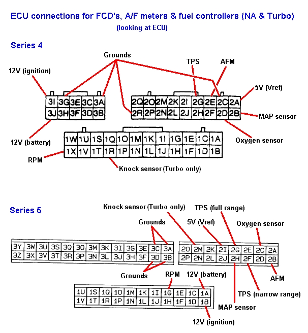
The term "ARB" (air bypass relay) from the write-up on TeamFC3S is misleading and incorrect. The black/white power wire on the diagnostic plug doesn't just feed the air bypass relay, it's the same circuit that feeds most of the engine's 12V sensors, all of the solenoids and the ECU itself (pin 3I). You can power the LED's from any 12V source if you wanted to.
To wire up the LED's at the ECU, power can come from pin 3I and the error code signals come from pins 1A and 1B. The rich/lean signal comes from pin 1D.
To wire up the LED's at the ECU, power can come from pin 3I and the error code signals come from pins 1A and 1B. The rich/lean signal comes from pin 1D.

Thread
Thread Starter
Forum
Replies
Last Post