When you click on links to various merchants on this site and make a purchase, this can result in this site earning a commission. Affiliate programs and affiliations include, but are not limited to, the eBay Partner Network.
Note: The following is information I've compiled to be used in diagnosing, fixing, modifying, or replacing your ECU & wiring. If you are not confident with reading wiring diagrams, repairing wires, or generally performing electronics repairs, please take your car to a professional. I am not a professional mechanic, and I am not responsible for any damage you may cause using the information in this post (whether or not you follow the post correctly). Please keep in mind that I myself compiled this using a combination of Mazda's diagrams and my own experience, so if something doesn't match or just plain feels wrong, back up and investigate before proceeding. Several wires marked as "not needed" are required for emissions purposes, meaning that removing them may be a violation of local law if your car is street driven. At the end of the day, this is just a tool for understanding the wiring, not a be-all-end-all guide. Do not go altering any wires without a clear understanding of what they do and why.
This is a compilation of information I've amassed about the stock ECU and wiring. Some of this is from the service manual, some from the training manual, some from the wiring diagram, and some are Excel spreadsheets I made for the purpose of adapting the stock harness for standalone ECU use. I thought it might be useful to others, so I've decided to post it here in case anyone else finds they need it.
What can you use this information for?
- Diagnosing an issue with the stock ECU, wiring, or sensors.
- Stripping down the stock harness for race applications.
- Making an adapter to use a standalone with the stock harness (not usually recommended due to age, but in my case I recently refurbished the stock harness and cost is a big factor).
First, here is the Excel sheet. This is for a Series 4 NA 5 speed car, but the differences in TII and AT cars is noted:
Notes:
- When the box is red, it denotes that a wire is not needed as far as a standalone installation is concerned. If stripping down the harness but retaining the stock ECU, wires 1E, 1J, 2F, 2H, 2J, and 3B are necessary.
- 1E is a special case: the ECU uses 1E to determine if the A/C is switched on, however it assumes the AC is off only when this pin receives 12V. This means that if you remove the stock wire, you need to feed this pin 12V to keep the ECU from locking zero split and changing the idle timing. I will provide a sheet from the training manual later that will clarify.
- The stock ECU grounds out through the harness at the ground point on top of the engine, but most standalone installations will ground out on a body bolt near the ECU. All the ground wires are black.
Second, here is the above spreadsheet with all of the unnecessary wires removed (just an example, NOT a complete guide):
Notes:
- As above, this is in reference to a standalone installation. The wires referenced in the previous notes will need to be retained for a stock ECU application.
- Yellow denotes "Optional" wires, depending on your specific installation. You may want to keep the P/S angle switch to tell the standalone to bump idle, or the neutral switch for idle detection, etc.
- Reference voltage shows as "optional", but is necessary unless you are running a new wire for the purpose (which may be recommended if your harness isn't in good shape to get accurate sensor readings). It is +5V for the sensor reference voltage, and this goes to the MAF (or MAP after standalone) and TPS.
- Stock O2 and AFM wires in this spreadsheet are repurposed for wideband and MAP use respectively. You will have to modify the old MAF wiring and old O2 wiring to match the new sensors, of course.
- Assumes you are using the IAT sensor in the dynamic chamber (or other IAT sensor on same wires), not the one in the AFM.
- Pin 3B may not be necessary depending on how your standalone determines whether the car is "cranking". If it is RPM based you can omit this wire.
And now for the FSM, wiring diagram, and training manual info that gave me all the above info:
Stock ECU Pinout and Diagnostics:
Note:
- The diagram above is as viewed from the ECU side, not the wire side.
- A neat trick to check each wire during diagnostics is to use a safety-pin. Use the pin side to backprobe the appropriate pin on the connector, with the tip of the multimeter probe in the other side of the safety pin (thanks to j9fd3s for the tip).
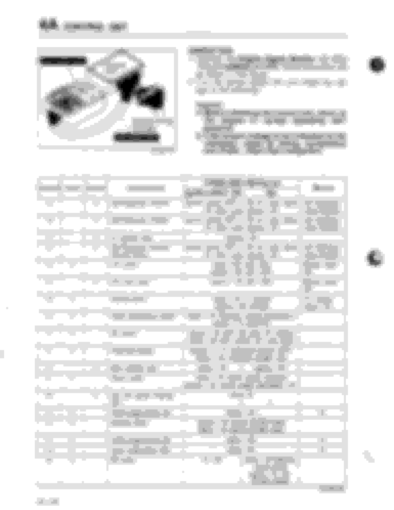
Series 4 NA Wiring Colour and Pinout (F-31, EM-03, EM-31):
Series 4 TII Wiring Diagram and Pinout (F-31, EM-03, EM-31):
Note:
- The above connectors F-31, EM-31, and EM-03 already have the wiring colour per pin denoted in the spreadsheet. In case you need it though, this is Mazda's code for each colour:
L = Blue
B = Black
BR = Brown
DL = Dark Blue
DG = Dark Green
G = Green
GY = Gray
LB = Light Blue
LG = Light Green
N = Natural ***I have not seen this colour used yet, nor do I know what they mean by "natural". If you do, please let me know***
O = Orange
P = Pink
R = Red
PU = Purple
T = Tan
W = White
Y = Yellow
V = Violet
The first colour in each pin is the main colour, second colour is the stripe. Some wires also have banding on them but I haven't noticed this in the diagram so I have ignored it for the time being.
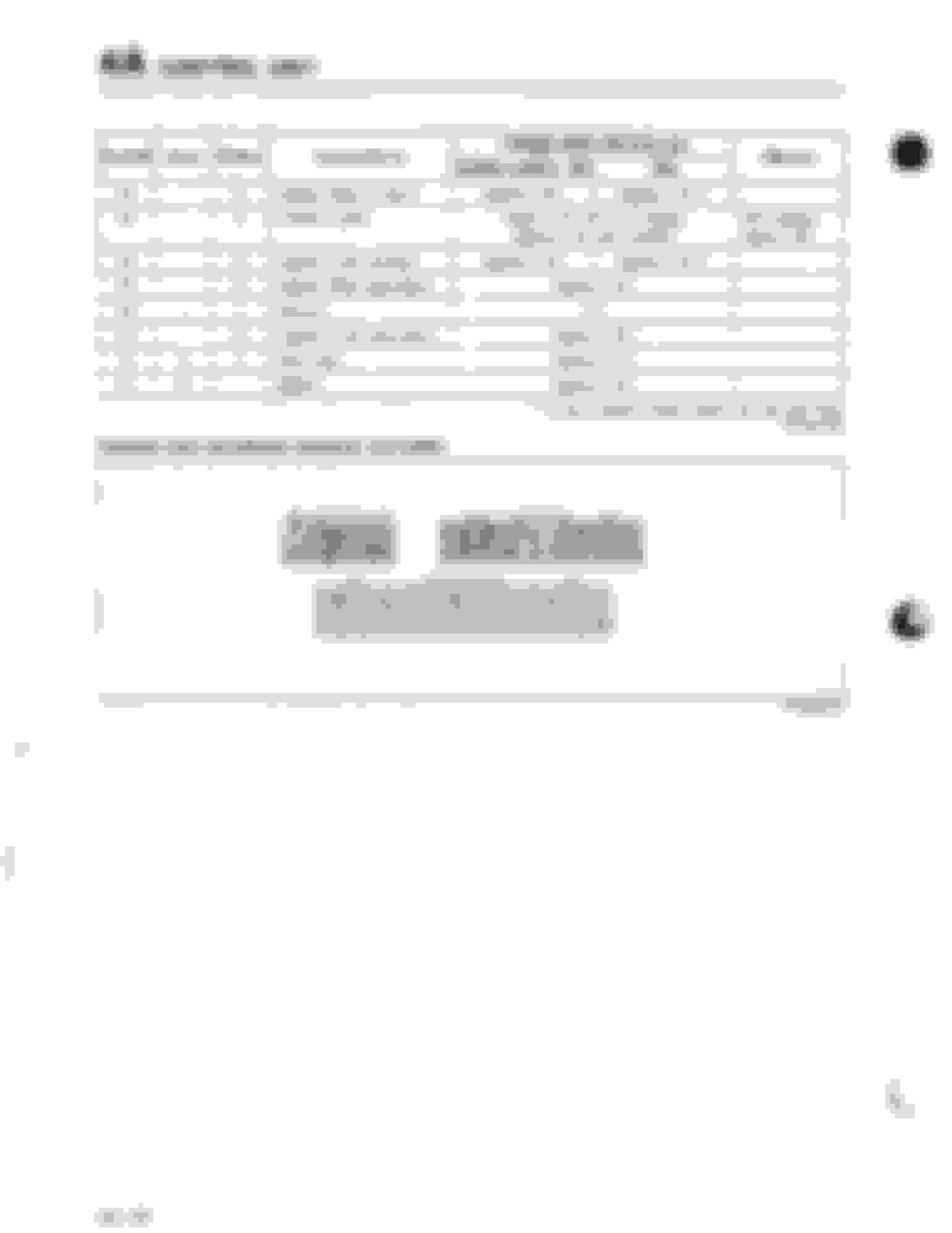
Lastly, here's a page from the training manual that notes when the stock ECU alters timing. You can see why pin 1E needs to see 12V, otherwise it will lock zero split and alter timing at idle. You can also see that while cranking the stock ECU uses different ignition timing, so you may want to implement this in the "cranking" setup of your standalone if you are having starting issues.
That about wraps it up, if I find more relevant information I will add it here. I've double checked everything a few times so as not to accidentally mislead anyone, but as I mentioned at the beginning I recommend double checking against the factory manual pages I've provided before doing anything to your wiring.
If you see any errors, issues, or other room for improvement, please comment below so this is a more complete resource.
EDIT: Oh, and I almost forgot, the Excel workbook is attached for your convenience.
Last edited by WondrousBread; Feb 11, 2022 at 02:10 PM.
Awesome! Even though the posts have slowed down, it seems that there are more detailed posts that have a good amount of research and solid info in them. A lot of good write-ups have been developed lately. Let's keep it up!
Awesome! Even though the posts have slowed down, it seems that there are more detailed posts that have a good amount of research and solid info in them. A lot of good write-ups have been developed lately. Let's keep it up!
The greatest advantage of the forum is permanence and searchability. I understand why many have migrated to Facebook or Instagram, but neither of those have the permanence of the Rx7Club.
Reddit has permanence, but trying to search it is a nightmare. R/rx7 is perfectly fine but it doesn't have the subsections, archives, etc. Meanwhile the search function on this forum (or using Google "search term site:www.rx7club.com") is far more robust.
This place is full of info, I was reading a thread yesterday that was 22 years old. Nearly as old as me.
The more we can contribute and maintain it, the more we document these cars for the future.
Dang, wish I had this when I was doing the wiring on my Megasquirt in December, saving everything
That's likely the way I will go (I mentioned cost is a factor, and MS3X has so many features for the cost that there's no comparison). I also like DIY stuff and MS is really well documented, so it doesn't look look too difficult. You can use the stock sensors too.
No matter which standalone I use, the idea is that I can now add the corresponding pins into the Excel worksheet and then have a guide on how to build the adapter. Injector resistors already built in. And then when complete I can share it all here as well.
So getting ahead of myself, here's my completed MS3X [almost] Plug-and-Play adapter:
The four ring terminals are all grounds. One bundle from MS3 mainboard, one from MS3X board, one from the stock harness, and the small one is the sensor ground and ground for the small section of CAS shield. I'm not sure if this small run of wire really needs shielding, but I added it anyways. I know normally the sensor ground would run out to the sensors at the engine, but I think this should be fine if all the grounds are good.
Harness connector taken from a damaged ECU I had around, then add 1 DB37 male, 1 DB37 female, and assorted wiring and you have it. I'm not going to finish wrapping it until I get a chance to actually test it out. This is designed working from a few sources: Stock ECU info above, MS3 hardware manual, Aaron's excellent guide and wiring diagram, and the DiyAutoTune article on how to install Megasquirt in an Rx7.
It is designed for the following configuration:
- BAC valve on MS3X PWM idle output.
- E-Fan control on MS3 FIdle output (requires 3.0 board and modification, instructions in the hardware manual).
- Stock IAT and CLT sensors. Requires changing two bias resistors inside the MS3 to 39k Ohm for accurate readings. Also keep in mind that one could just change the sensors and connectors to GM units and not modify the resistors, and also that the stock IAT sensor is slow to react. In turbocharged applications you want a fast-acting sensor, like the Triumph unit popular on FDs or the GM alternative.
- Stock CAS and ignition setup.
- One weird thing I noted, the stock CAS wiring in the FSM is slightly different than all the diagrams I have seen above. Red, green, and white are consistent. However both the DiyAutoTune guide and Aaron's guide list the last wire as "white with a black stripe." The FSM lists it as "blue". It is possible the wire changes colour somewhere in the harness. When I pull the stock ECU I will make note of the colour.
- Fuel pump rewired with relay, triggered by the MS3 fuel pump output. This is why it's "almost" plug-and-play.
Wideband, boost controller, extra tach output, launch control button, and e-fan trigger are set aside to be made into a sub-harness. More outputs and inputs could be added into the DB37s later as needed, but to keep things simple and the wiring neat I've stuck with the basics for now.
Backwardly enough I've accumulated everything for the MS3X installation except the MS3X itself. I'll release the updated spreadsheet as soon as I actually have the MS3X and get a chance to test it. I gave plenty of disclaimers at the beginning of this thread, but if someone is going to burn their MS3X or their wiring due to this diagram I'd rather I go first