
Broke S4 T2 intake mani, S5 swap?

Thread Starter
Joined: Dec 2006
Posts: 1,973
Likes: 0
From: Prince George, BC
Broke S4 T2 intake mani, S5 swap?
Well today was a fail of a day. I was so excited to install my 750 rc engineering injectors. Everything was lined up and started driving the screws into the fuel rail. I had 1 screw almost all the way tightened, while the other wasn't close. So I kept on it and it was starting to get tight, the screw wasn't even close to the rail. Decided to give it a couple more turns than throw in the hat and decide its hopeless. Yea that's right you guessed it, the screw hole on the lower intake manifold snapped off. 
Now I have to disturb the oil injectors lines, not stoked on that. Have to remove the bnr again, and to top this **** of course the lower intake manifold.... I came to the conclusion to go with an s5 setup.
Question... I searched and searched and couldn't find nothing. There's alot on n/a but not turbo. The car is an 87 t2 with no emissions, rats nest removed. I wanted to keep the bac, tps, and water thermo pellet. Pretty sure it's doable. But just wanted to find something solid. If it's doable what has to be done?
I know alot of you are going to say its pointless go with the s5 setup because the gains are minimal. But going ahead and even upgrading it just to get 10hp in the end .. Is worth it to me because I have to go through it anyway, and will make me feel like breaking the s4 mani was meant to be.
EDIT: 1500 POST!
So you have the bolt broken off in the lower manifold correct? Why don't you remove the upper mani, then drill the bolt out and retap it. Much easier than swapping manifold setups.
S5 LIM & UIM, S4 TB & spacer, S4 BAC. The S4 & S5 TII manifolds are largely the same, but you'll have little differences like the air bleeds and maybe the nipple layout near the TB. I can't remember all the details; it's been awhile since I had an S5 TII manifold set to look at.
Thread Starter
Joined: Dec 2006
Posts: 1,973
Likes: 0
From: Prince George, BC
The only vacuum sources I need is fpr, and the 2 bottom lines on the upper intake manifold.
Can anyone peep in and tell me exactly what I need to know. Even a link would be great. So far into detail as, does the s4 throttle cable link on fine? Cruise control? Water line underneath uim? S4 TPS?
Thanks for that rotaryrocket88, gave me the jist of it.
Can anyone peep in and tell me exactly what I need to know. Even a link would be great. So far into detail as, does the s4 throttle cable link on fine? Cruise control? Water line underneath uim? S4 TPS?
Thanks for that rotaryrocket88, gave me the jist of it.


I recently did this swap on my motor build. I have a weird hybrid of s4, s5, and FD parts on my car. To summarize, it will be a lot easier if you can find USDM ones because of a bunch of small differences. But because the s5 manifold runners are larger than the s4 port runners, I'm not sure you will pick up any gain from this and it may not be worth it. Now here's the full explanation:
I have JDM S5 T2 irons and intake manifolds. The S5 intake port runners are larger than the s4, and therefore so are the runners on the intake manifold. I switched to s5 irons because I wanted their increased strength, and then when I saw the differences in port design I decided to get s5 manifolds to keep the airflow smooth. If you look compare the s5 and s4 T2 gaskets you can see the differences. I think you should be able to just bolt the s5 LIM in and use the gasket, but the air will basically hit a wall as the larger s5 manifold runners hit smaller s4 intake port runners. You could smooth this transition with porting, but you have the engine together. IMO this is a significant reason not to do the swap. With the engine in the car you can't see the differences in port runner sizes unless you compare the s4 T2 and s5 LIM T2 gaskets.
To mount the S4 TB on the s5 UIM you have to back one stud out slightly, this isn't a big deal. If you go with JDM manifolds (and you probably will, who has USDM s5 T2 manifolds just lying around?), you have a couple extra issues to deal with. You have the brake booster. On the USDM manifolds, the brake booster hose is on the back of the UIM. On the JDM manifolds, it is on the back of the rear primary runner. There is a little metal hardline thing I think. In my case, I didn't have whatever OEM piece went in there.
I tapped the hole on the runner I believe 3/8 NPT (double check that size) and used a 90 degree NPT to 3/8" barb brass fitting. Then I used 3/8" heater hose to run it to the firewall hard line. The firewall hardline (at least on my car) has two pieces. I unbolted the very bottom piece where the brake booster hose normally goes to, the one that points toward the ground. If you unbolt that, what's left of the hard line is pointed toward the passenger side. This makes connecting the brake booster hose easy and with no kinks.
I retained the s4 T2 OMP and TPS, there were no issues with that once you get the TB installed.
When you try to bolt the UIM to the LIM, the big bolt in the middle is different on the s5's. I had to go to the dealer for this, it is not easy to find. I believe the s5 is 130mm long and the s4 is 110 mm long, but I can't swear those numbers are right. The s5 UIM runners are taller so the bolt has to be longer. All the other fasteners are the same.
On the s5 T2 JDM intake manifolds (unsure about USDM, again I've never seen those manifolds actually off a car), the BAC design is different from the S4 T2. If you look at the S4 T2 BAC area and the S5 JDM T2 BAC area with the valve not bolted on, you will see several differences.
First, the s4 T2 has a large barb on the back pointed almost towards the firewall which the S5 T2 does not have. I think this feeds the air supply valve (P/S idle compensation) and air bypass solenoid valve (accelerated warmup). I know the JDM S5's don't have those two and I'm pretty sure the USDM don't either, so no blockoff plate is needed. The manifolds I had also did not have sub zero start assist, and no S5's had EGR. So overall the s5's are much cleaner looking than the s4.
The second thing about the JDM s5 intake manifold BAC area is that the adjuster screw on the BAC valve is not going to work. On the USDM s4 T2 manifolds, the BAC valve feeds air through a big hole leading to the primary runners. The adjuster screw on the side of the BAC adds extra in even when the BAC valve is closed. It flows down a small passageway that is casted into the side of the s4 T2 USDM BAC area. The JDM S5 T2 does not have that (and neither do the S4 JDM T2's apparently), as the JDM BAC valve does not even have an adjuster screw on it. If you have a USDM s4 T2 BAC valve on a JDM S5 T2 UIM (as I do) it is best to shut the adjuster screw and set your base idle speed using the throttle stop screw on the TB. It's a bit harder to get a fine adjustment of the idle but it's not a huge deal--or at least, it wasn't on my Power FC. Another interesting thing I noticed was that the holes inside the BAC flange on the UIM which lead to the runners were bigger on the S5.
Finally, you may have throttle and cruise control cables to deal with. I'm not sure about on USDM S5 T2, but on the JDM S5 T2 I had to significantly modify the throttle/cruise control cable bracket and the cruise control cable. I did not want to give up cruise control (absolutely pointless to eliminate this, it accomplishes nothing). I discussed this in another thread: https://www.rx7club.com/2nd-generation-specific-1986-1992-17/jdm-s5-t2-throttle-cable-problem-700735/ . You have to widen the holes of the S5 T2 JDM bracket so that you can move the entire bracket forward (towards the driver's side). That allows you to tension the throttle cable correctly. The cruise control cable required that I grind down much of the end so that it would slide through the bracket properly and could be tensioned. You may be able to just swap in the USDM s4 T2 bracket and it will all work (doubt it will be perfect though because the manifolds are different), but my dumb *** had already thrown all that **** away because I needed space.
That's everything. You're lucky I have a photographic memory.
Originally Posted by arghx
First, the s4 T2 has a large barb on the back pointed almost towards the firewall which the S5 T2 does not have. I think this feeds the air supply valve (P/S idle compensation) and air bypass solenoid valve (accelerated warmup). I know the JDM S5's don't have those two and I'm pretty sure the USDM don't either, so no blockoff plate is needed. The manifolds I had also did not have sub zero start assist, and no S5's had EGR. So overall the s5's are much cleaner looking than the s4.
The second thing about the JDM s5 intake manifold BAC area is that the adjuster screw on the BAC valve is not going to work. On the USDM s4 T2 manifolds, the BAC valve feeds air through a big hole leading to the primary runners. The adjuster screw on the side of the BAC adds extra in even when the BAC valve is closed. It flows down a small passageway that is casted into the side of the s4 T2 USDM BAC area. The JDM S5 T2 does not have that (and neither do the S4 JDM T2's apparently), as the JDM BAC valve does not even have an adjuster screw on it. If you have a USDM s4 T2 BAC valve on a JDM S5 T2 UIM (as I do) it is best to shut the adjuster screw and set your base idle speed using the throttle stop screw on the TB. It's a bit harder to get a fine adjustment of the idle but it's not a huge deal--or at least, it wasn't on my Power FC. Another interesting thing I noticed was that the holes inside the BAC flange on the UIM which lead to the runners were bigger on the S5.
The second thing about the JDM s5 intake manifold BAC area is that the adjuster screw on the BAC valve is not going to work. On the USDM s4 T2 manifolds, the BAC valve feeds air through a big hole leading to the primary runners. The adjuster screw on the side of the BAC adds extra in even when the BAC valve is closed. It flows down a small passageway that is casted into the side of the s4 T2 USDM BAC area. The JDM S5 T2 does not have that (and neither do the S4 JDM T2's apparently), as the JDM BAC valve does not even have an adjuster screw on it. If you have a USDM s4 T2 BAC valve on a JDM S5 T2 UIM (as I do) it is best to shut the adjuster screw and set your base idle speed using the throttle stop screw on the TB. It's a bit harder to get a fine adjustment of the idle but it's not a huge deal--or at least, it wasn't on my Power FC. Another interesting thing I noticed was that the holes inside the BAC flange on the UIM which lead to the runners were bigger on the S5.
It's also interesting that you point out that the S5 JDM UIM doesn't have a path for BAC air, and that the S5 BAC doesn't have an adjuster screw. The S4 JDM BAC does have the screw, and the S4 JDM UIM does have a path into the runners. I don't remember that difference, and it's odd that Mazda would have changed it (I had a couple of JDM S5 engines to work with years ago). I suppose port matching an S4 UIM to the S5 LIM runner size might work, if there's room to spare.
My engine is a mix of S4 JDM and USDM parts. My block, UIM, TB and most other parts are JDM, but my LIM is USDM because I needed to be able to bolt an EGR valve on for appearances (CA smog). I also drilled and tapped the USDM LIM to accept the nipple and banjo bolt for the JDM brake booster line. There was even a nice little flat spot where the two castings were the same.
Trending Topics
Thread Starter
Joined: Dec 2006
Posts: 1,973
Likes: 0
From: Prince George, BC
Arghx strikes again! Thanks man! Everything I needed to know.
So would you actually go as far as saying that s5 would kill the performance, due to the runner size difference?
So would you actually go as far as saying that s5 would kill the performance, due to the runner size difference?
It's also interesting that you point out that the S5 JDM UIM doesn't have a path for BAC air,
I have hooked up a pressurized air source to a BAC valve that was off the car in order to observe how the air flows. I have also physically cut a BAC valve open to look inside. The main air feed leads into a chamber. The main part where the chamber mates with the UIM is closed by a spring loaded plunger. That plunger is pulled back by a magnet when +12V is applied as the valve is duty controlled. On the USDM turbo BAC, there is a small separate passageway leading from that main chamber inside. That air flows into the UIM regardless of whether +12V is applied to the magnetic coil. The amount of air that blows is regulated by the adjustment of the screw. The air flows out of the BAC valve into a channel that is cast into the mating surface of the BAC valve. The channel directs the air into the main BAC opening of the UIM.
I have physically hooked up an air compressor to a BAC to observe this. Without +12V applied to the magnetic coil, a trickle of air flows through the small passageway controlled by the screw, as long as the screw is not completely tight. The more the screw is open, the more air will flow when the plunger is closed. When the plunger is pulled back by the magnetic coil (+12V applied), air continues to flow into the manifold through the small passageway.
In this way, the adjuster screw effectively acts as a Y intercept for the linear bypass air curve that is determined by the duty cycle of the valve.
It does have a path for BAC air, sorry if I wasn't clear. It just doesn't have a path for the extra bypass air which is not duty controlled, the one that is controlled by the screw. There is a big hole in between the two bolt holes just like on an S4. On the s4, you can see two small holes in the casting of the main opening, the one that is duty controlled by the BAC. On the S5 JDM, these two small holes are much bigger for some reason. They have got to be twice the diameter of the S4.
I have hooked up a pressurized air source to a BAC valve that was off the car in order to observe how the air flows. I have also physically cut a BAC valve open to look inside. The main air feed leads into a chamber. The main part where the chamber mates with the UIM is closed by a spring loaded plunger. That plunger is pulled back by a magnet when +12V is applied as the valve is duty controlled. On the USDM turbo BAC, there is a small separate passageway leading from that main chamber inside. That air flows into the UIM regardless of whether +12V is applied to the magnetic coil. The amount of air that blows is regulated by the adjustment of the screw. The air flows out of the BAC valve into a channel that is cast into the mating surface of the BAC valve. The channel directs the air into the main BAC opening of the UIM.
I have physically hooked up an air compressor to a BAC to observe this. Without +12V applied to the magnetic coil, a trickle of air flows through the small passageway controlled by the screw, as long as the screw is not completely tight. The more the screw is open, the more air will flow when the plunger is closed. When the plunger is pulled back by the magnetic coil (+12V applied), air continues to flow into the manifold through the small passageway.
In this way, the adjuster screw effectively acts as a Y intercept for the linear bypass air curve that is determined by the duty cycle of the valve.
So you have an S5 JDM BAC that doesn't have an adjustment screw? I don't remember if the two I had did or did not, but as far as an adjustment screw on the S5 JDM TB, I doubt it. TII TBs are upside down when compared to NA TBs that have the adjustment screw, so there's no good mounting location on "top." And then there's the problem of the intercooler. It would completely block access to that area, and make adjustments a serious pain.
So you have an S5 JDM BAC that doesn't have an adjustment screw?
The funny thing was, I ended up getting that USDM one after I cut open the JDM valve because I wanted to be able to have an adjuster screw. But I didn't realize at the time that a USDM BAC valve on a JDM manifold still results in no idle screw adjustment capability because the casting needed for the screw to work is not on the manifold. So I just closed the screw shut and adjusted the idle exclusively with the throttle plate adjustment screw, then adjusted BAC valve behavior in my Power FC after the TPS was set. It all worked out, but I could have just used the JDM one the whole time. If you know what you're doing, you can use the Power FC's closed-loop idle control function to dynamically adjust timing to smooth the vacuum signal and idle speed.
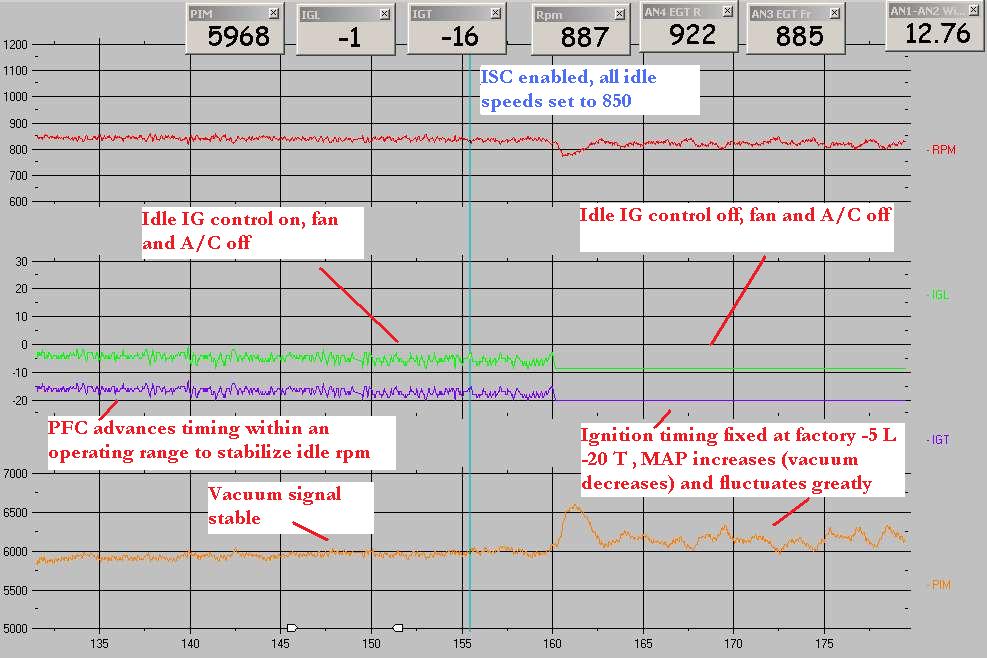

ISC is FD terminology for BAC valve; the graphs are RPM, ignition timing advance, and MAP using the Power FC load coordinate system. You can see the Power FC idling up for my efan and adjusting timing. In this log I switch closed loop idle ignition control on and off. Many FD owners doubted the usefulness of this function, so I tested it myself and posted that in another thread in the 3rd gen section.
I have a large streetport and it idles almost like it's stock, very little brap brap. Vacuum signal is about 12 inches with 2mm apex seals, good condition housings, and brand new side and corner seals clearanced to 2 thousandths. In the Power FC there are settings which indirectly adjust BAC valve duty and target idle speed as you decelerate, effectively a virtual dashpot function. It's pretty cool when you figure it all out, but maddening if you don't know exactly how idle speed control systems work. People knock the Power FC, and it does have limitations, but most of the driveability quirks are a result of poor documentation of how everything works.
Also, I have an FMIC. Setting idle would be a son of a ***** with the top mount. I would've used a home depot TMIC bypass pipe per NZConvertible for setting idle with the engine running.

Thread
Thread Starter
Forum
Replies
Last Post
trickster
2nd Generation Specific (1986-1992)
25
Jul 1, 2023 04:40 PM
Azevedo
Other Engine Conversions - non V-8
26
Mar 1, 2019 09:19 PM
immanuel__7
2nd Generation Specific (1986-1992)
89
Sep 5, 2015 10:23 AM