
Big Turbo Time! Midsummer 2007 Pics/Update On My Turbo-NA Bridgeport Project


It is an internal restrictor, but you still need a .035" external unit...

Thread Starter
Joined: Feb 2001
Posts: 29,798
Likes: 128
From: London, Ontario, Canada
What he said. I asked the local turbo builder about this years ago and they said something like 'if the oil pressure is over 30 PSI at the turbo oil inlet, you need a restrictor".
Cheap and easy way to make one: get a 1/8" NPT male/female adapter and the solder it full. Now drill out the hole to 0.35".
Cheap and easy way to make one: get a 1/8" NPT male/female adapter and the solder it full. Now drill out the hole to 0.35".
Where is your coolant feed for the turbo coming from...and is the coolant deposit going to the bottom nipple on the water-pump lower neck? The reason why I am asking is that my S5 LIM original coolant feed location is permanently welded (bought off a forum member a while back) so i need a different feed location for my turbo (GT35R). My previous turbo was just oil lubricated and oil cooled, now I went with ball bearing and want it to stay as cool as possible.
Thread Starter
Joined: Feb 2001
Posts: 29,798
Likes: 128
From: London, Ontario, Canada
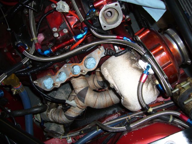
Coolant feed to the turbo comes from the rear iron nipple.
Originally I clamped a hose to it, though now I have a compression fitting on the nipple to an NPT fitting, which then goes to AN. Coolant then feeds to the back of the water pump housing in the stock return location.
Here's an image from a few years later:
Originally I clamped a hose to it, though now I have a compression fitting on the nipple to an NPT fitting, which then goes to AN. Coolant then feeds to the back of the water pump housing in the stock return location.
Here's an image from a few years later:
 . What size drill did you use on the rear housing (coolant feed for your turbo)? and what size drill for the waterpump (coolant return)? I am debating on whether or not I should drill/tap my rear housing and waterpump (my rear iron has the nipple still there but jbwelded shut, waterpump nipple is jbwelded shut as well...and looks horrendous). I already have 4ft of leftover braided fuel line left over and a bunch of 6AN fittings left over from the build. Should I tap them even with the risk of cracking the rear iron and getting fillings in my coolant???
Thread Starter
Joined: Feb 2001
Posts: 29,798
Likes: 128
From: London, Ontario, Canada
I believe the original coolant return on the S4 and S5 turbo was on the bottom of the waterpump.
.
What size drill did you use on the rear housing (coolant feed for your turbo)? and what size drill for the waterpump (coolant return)?
NPT Tap Drill Sizes - Engineer's Handbook
I am debating on whether or not I should drill/tap my rear housing and waterpump (my rear iron has the nipple still there but jbwelded shut, waterpump nipple is jbwelded shut as well...and looks horrendous). I already have 4ft of leftover braided fuel line left over and a bunch of 6AN fittings left over from the build. Should I tap them even with the risk of cracking the rear iron and getting fillings in my coolant???
The rear iron is fairly brittle cast iron. I would only suggest drilling and tapping it if the engine is disassembled and you have enough experience to go slowly. Yes, I have seen them crack. See this video for a demo of the water pump housing and iron tapping process:
So what you are saying is this right.

Even as I type I am debating in my head whether or not I should use a compression fitting or just tap the hole. I might just go full retard and just tap the damn rear housing with a 1/4" NPT tap as you stated in your video.
Now I am not trying to call you out or flame, but when I was researching how to do this, I came across this thread and found that the info was conflicting with your Cosmo Build video post (granted that this thread was from 2008).
https://www.rx7club.com/2nd-generati...es-13b-746285/
On that older forum thread/post you had said to another member, "The small water nipples can be drilled and tapped out to 1/4" NPT, while the rear iron should be drilled and tapped out to 1/2" NPT being VERY CAREFUL not to crack it." But in your Cosmo Build Video you said that you "drilled out the stock coolant feed in the rear iron and am now carefully tapping it for 1/4" NPT"...am I mixing two different nipples on the rear housing up?

Thank You for your help
I went ahead and wiggled/removed the nipple and tapped the rear plate for a coolant feed for my turbo (which answers my question on the previous post) with 1/4" NPT to AN 6 fitting. I also did the same for the waterpump, removed the stock coolant 90degree elbow nipple and tapped it for 1/4" NPT as well (for a coolant return from the turbo). That 90degree elbow was originally for the coolant return from the BAC. I should have done all this when the engine block was outside of the vehicle. LIVE AND LEARN
Thread Starter
Joined: Feb 2001
Posts: 29,798
Likes: 128
From: London, Ontario, Canada
By 1/2" NPT, I was likely referring to the nipple which supplies water to the heater core. And in fact 1/2" NPT is pretty risky. Better would be a straight thread like M16 and then seal it up with a crush washer (probably ened to mill the area flat).
Thank You for your help.
Junior Member
Joined: Mar 2014
Posts: 16
Likes: 0
From: Miami
Aaron, whats your whole exhaust set up like? i saw vibrant resonator, whta muffler and piping are you using to quiet it down?? i have 13b bridgeport na but its extremely loud. i was wondering if you could help me with the proper set up please!
Thread Starter
Joined: Feb 2001
Posts: 29,798
Likes: 128
From: London, Ontario, Canada
9 year thread necromancy!
So the whole exhaust is something like this:
-3.5" SCH10 downpipe w/recirculated wastegate from turbo to about end of bellhousing area
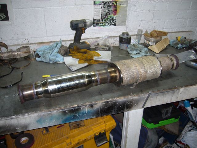
-3" 304 stainless thick walled tubing midpipe containing Vibrant 1795 (or 1795, I'd have to check) bottle style resonator followed by Vibrant 1142 Ultra Quiet resonator at about the Y pipe location
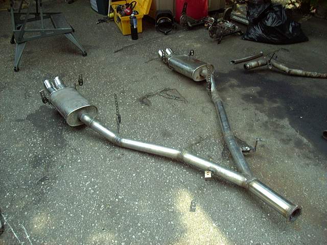
-Y pipe with fabricated split starting as 3" and splitting to two 2.5" pipes, thick walled stainless 304
-Two dual tip "DTM" style mufflers of imported origin, ordered from Japan way back in the '90s before every company reproduced them. Stainless packed, polished stainless. Think the tips are 2.5"
I've spent a LOT of time pondering and building rotary exhaust to be quiet. And there are a few key factors into it.
First, thick walled stainless for the downpipe. Which means, SCH 10 pipe or similar thickness. That's like 1/8" thick. It takes out all of the resonance, pinging and high pitched bee sounds. Yes, a bit heavier.
Follow up in the midpipe with the bottle style resonator. That doesn't take a lot of sound out of it, but works to further reduce the high frequencies and take the concussive pulses out of the exhaust.
Then the Ultra Quiet style resonator. Note that both these resonators are straight through. You can look directly through them. Impact on flow is negligible. The Ultra Quiet is packed with stainless and is where the majority of sound absorption takes place. it pulls out all the high notes leaving only the lows. Drone happens when standing waves form. The two resonators break up any standing waves. VERY important to place resonators so that they have a fair amount of tubing before and after. This greatly enhances their efficiency.
Dual exhaust. Single exhausts are stupid and very, very difficult to keep quiet while maintaining flow. Seems like Mazda knew what they were doing, eh?
Mufflers should be an offset type. Flow through, but offset. That offset doesn't reduce flow much, but makes an enormous difference in sound. Stainless packed only or if your exhaust temps are not too high, then fibreglass packed will work with reduced life. By the far end of the car, EGTs are much lower. Biggest mufflers you can fit under the car.
And of course, putting a muffler right at the engine in the form of a turbine chops a lot of sound out as well.
For your NA bridgeport, you may find offset mufflers too restrictive and the result may be a decrease in midrange. That's the problem with NA bridgeports. They are extremely sensitive to exhaust backpressure and it is exceedingly challenging to keep them quiet yet keep the flow up.
My suggestion would be to take a similar approach to what I did on my Cosmo for the midsection. Use an Ultra Quiet resonator, follow that up with a straight through MUFFLER, split off into the Y pipe, and place a bottle style resonator in each branch of the Y. Then you can use straight through mufflers and add a set of resonated tips.
So the whole exhaust is something like this:
-3.5" SCH10 downpipe w/recirculated wastegate from turbo to about end of bellhousing area
-3" 304 stainless thick walled tubing midpipe containing Vibrant 1795 (or 1795, I'd have to check) bottle style resonator followed by Vibrant 1142 Ultra Quiet resonator at about the Y pipe location
-Y pipe with fabricated split starting as 3" and splitting to two 2.5" pipes, thick walled stainless 304
-Two dual tip "DTM" style mufflers of imported origin, ordered from Japan way back in the '90s before every company reproduced them. Stainless packed, polished stainless. Think the tips are 2.5"
I've spent a LOT of time pondering and building rotary exhaust to be quiet. And there are a few key factors into it.
First, thick walled stainless for the downpipe. Which means, SCH 10 pipe or similar thickness. That's like 1/8" thick. It takes out all of the resonance, pinging and high pitched bee sounds. Yes, a bit heavier.
Follow up in the midpipe with the bottle style resonator. That doesn't take a lot of sound out of it, but works to further reduce the high frequencies and take the concussive pulses out of the exhaust.
Then the Ultra Quiet style resonator. Note that both these resonators are straight through. You can look directly through them. Impact on flow is negligible. The Ultra Quiet is packed with stainless and is where the majority of sound absorption takes place. it pulls out all the high notes leaving only the lows. Drone happens when standing waves form. The two resonators break up any standing waves. VERY important to place resonators so that they have a fair amount of tubing before and after. This greatly enhances their efficiency.
Dual exhaust. Single exhausts are stupid and very, very difficult to keep quiet while maintaining flow. Seems like Mazda knew what they were doing, eh?
Mufflers should be an offset type. Flow through, but offset. That offset doesn't reduce flow much, but makes an enormous difference in sound. Stainless packed only or if your exhaust temps are not too high, then fibreglass packed will work with reduced life. By the far end of the car, EGTs are much lower. Biggest mufflers you can fit under the car.
And of course, putting a muffler right at the engine in the form of a turbine chops a lot of sound out as well.
For your NA bridgeport, you may find offset mufflers too restrictive and the result may be a decrease in midrange. That's the problem with NA bridgeports. They are extremely sensitive to exhaust backpressure and it is exceedingly challenging to keep them quiet yet keep the flow up.
My suggestion would be to take a similar approach to what I did on my Cosmo for the midsection. Use an Ultra Quiet resonator, follow that up with a straight through MUFFLER, split off into the Y pipe, and place a bottle style resonator in each branch of the Y. Then you can use straight through mufflers and add a set of resonated tips.

Thread
Thread Starter
Forum
Replies
Last Post