
Air Temp Sensor Voltages


Thread Starter
Joined: Aug 2001
Posts: 2,515
Likes: 1
From: MISSISSAUGA, ONT. CAN
Air Temp Sensor Voltages
Does anyone happen to know what the Voltage readings range from on the S4TII air temp sensor? And of course what the voltages correspond to in temps. I am planning to hook it up to my Datalogger and need to know this info. I've tried looking through the FSM but i didnt seem to find it....
Thanks
Thanks

HAILERS
Joined: May 2001
Posts: 20,563
Likes: 27
From: FORT WORTH, TEXAS,USA
Your not going to find that information in my humble opiinion. About the only way I know of to do that and it be an easy chore (I don't like doing chores) is to own a RTEK2.0 and pull up the page that displays intake temperature. Then, starting with a cold engine and a volt meter on the input pin on the ECU for that temp sensor, start the engine.
When say 100 degrees shows up, look at the meter and write down the voltage for 100 degrees and on and on and on and on til the temp max's out. Then disconnect the radiator fan and let the temps really climb up the wall so you can keep on logging (humor)
When say 100 degrees shows up, look at the meter and write down the voltage for 100 degrees and on and on and on and on til the temp max's out. Then disconnect the radiator fan and let the temps really climb up the wall so you can keep on logging (humor)

Rotary Enthusiast
Joined: Oct 2001
Posts: 1,022
Likes: 4
From: Ontario, Canada
The Mazda sensors are std NTC type thermistors. I have software to model these, and generate lookup tables for standalone applications. Let it sit overnight, then measure the ambient temperature and the voltage with the key on prior to startup. Send me that voltage/temperature pair, and I'll generate a lookup table T(V). It won't be linear due to the logarithmic response of these type of sensors.
HAILERS
Joined: May 2001
Posts: 20,563
Likes: 27
From: FORT WORTH, TEXAS,USA
Originally Posted by renns
The Mazda sensors are std NTC type thermistors. I have software to model these, and generate lookup tables for standalone applications. Let it sit overnight, then measure the ambient temperature and the voltage with the key on prior to startup. Send me that voltage/temperature pair, and I'll generate a lookup table T(V). It won't be linear due to the logarithmic response of these type of sensors.
And to muddy the water, I put a K probe of a Fluke meter in the inlet duct near the intake temp sensor (the one on the throttle body) and compared the reading on the RTEK vs the K probe. Well after idling for a bit the RTEK2.0 read 95 degrees while the K probe was reading in the low 70's.
So I removed the K probe that was hanging in mid air inside the duct and held it against the throttle body elbow where the stock temp sensor is. The duct itself read in the mid 90's with the K probe just like the stock sensor.
So what I'm saying, is, I don't see how these engine managment systems get thru life. The heat of the metal intake duct gets to the stock sensor and makes it read higher than the actual air entering and passing thru the duct. You know what I mean. The air temp is actually 72 degrees but the heat off the duct makes the stock temp sensor read in the mid 90's.
The less I think about it the better off I am. There's nothing one can do about it. I'd bet those after market management systems are similar to the stock placement of the temp sensors. S u c k s
Rotary Enthusiast
Joined: Oct 2001
Posts: 1,022
Likes: 4
From: Ontario, Canada
Measurement accuracy is another issue... I believe the stock FC system uses two air temp sensors, with one in the manifold or TB elbow, and the other in the AFM. The designers of the stock ecu will have some basis for selecting one sensor or the other, or perhaps even a blend of the two inputs to compensate for those heat-soaking issues.
In my standalone install heatsoak was an issue with the stock sensor location in the S4 NA manifold. After switching to a TII intake the sensor was mounted in an S4 NA plastic elbow, and the problem has all but disappeared.
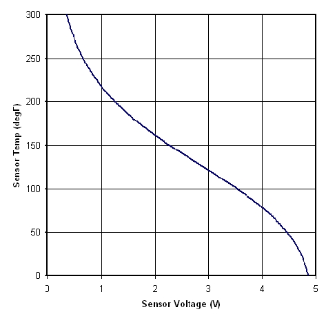
Attached is the conversion graph using the 'hailers' data of 67.7F = 4.19V. The zip file contains the data used to plot the graph. Hope that helps.
In my standalone install heatsoak was an issue with the stock sensor location in the S4 NA manifold. After switching to a TII intake the sensor was mounted in an S4 NA plastic elbow, and the problem has all but disappeared.
Attached is the conversion graph using the 'hailers' data of 67.7F = 4.19V. The zip file contains the data used to plot the graph. Hope that helps.

Thread
Thread Starter
Forum
Replies
Last Post
troym55
3rd Generation Specific (1993-2002)
23
May 25, 2016 12:42 PM