
2009 Updates On My Turbo-NA Bridgeport Project (Project Tina)

Thread Starter
Joined: Feb 2001
Posts: 29,798
Likes: 128
From: London, Ontario, Canada
2009 Updates On My Turbo-NA Bridgeport Project (Project Tina)
It's been more then a year since I posted the last thread about my ongoing project. There has been such a lag in threads mainly because it is almost done. I've just been driving the car and enjoying it. But there is still a little work to do not only involving further modifications, but also to replace some weak links as well. This update primarily deals with two tasks; installing a boost controller and fabricating a new 100 litre fuel tank. Near the end, I also start prepping the car for a TII transmission swap.
We begin where we left off last year; the installation of the rear strut bar. As detailed in the last thread, the strut bar was fabricated from 6061 aluminum as a first project after purchasing a TIG welder.
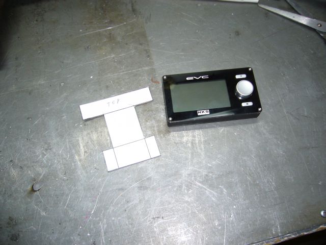
Since I installed the GT40R in 2007, I had been running on the 0.9 bar wastegate spring. Consequently the car made 13 PSI almost exactly. Even though the turbo is falling asleep at this pressure, the car managed to put down 392 RWHP on the dyno. A little more tuning after that to smooth out the top end and midrange of the map put the car at around 420 RWHP (measured on my calibrated butt dyno). Not too shabby at all, but a little more boost was needed to wake up the turbo and also eliminate some lag as the wastegate started to crack open before full boost was reached. I chose the HKS EVC 6 boost controller because it is a closed loop electronic boost controller with a load of useful features. Of course, what I mostly wanted was an electronic "dial a boost" that would simply make the pressure I set it too without a lot of tweaking or manually editing solenoid duty cycles. As the ECV 6 has two boost settings (well, technically 3 if you count scramble boost) I planned to have the low boost set at 14 PSI, and then the high boost set at whatever results in 500 RWHP.
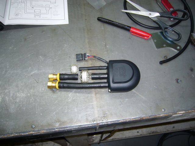
Before all the fun though, the controller must be installed. My existing wastegate line is braided stainless with AN fittings, so I needed to adapt the lame nipples HKS put on the solenoid (really a stepper motor) to NPT fittings or AN flares. Seriously HKS, this is a $600+ boost controller, is it too much to ask for NPT ports instead of plastic nipples? As it turns out, a friend had come back from the hydraulic store with some Push-Lock -4 hose barbs which fit the HKS supplied hose perfectly, so I grabbed two and mocked up the assembly.
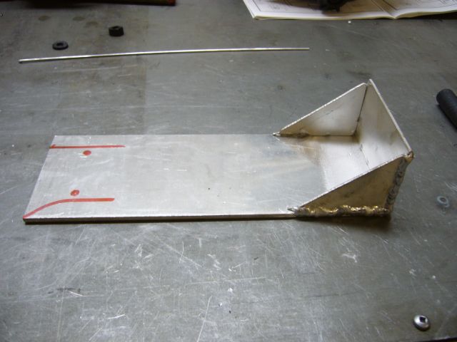
A bracket was needed to mount the solenoid assembly to the car, so I began fabricating one out of some 1/16" aluminum sheet.
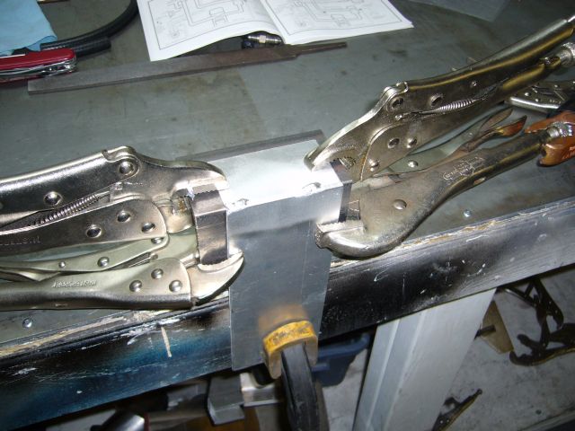
Here is the bracket fully welded with the solenoid mounting position and holes marked.
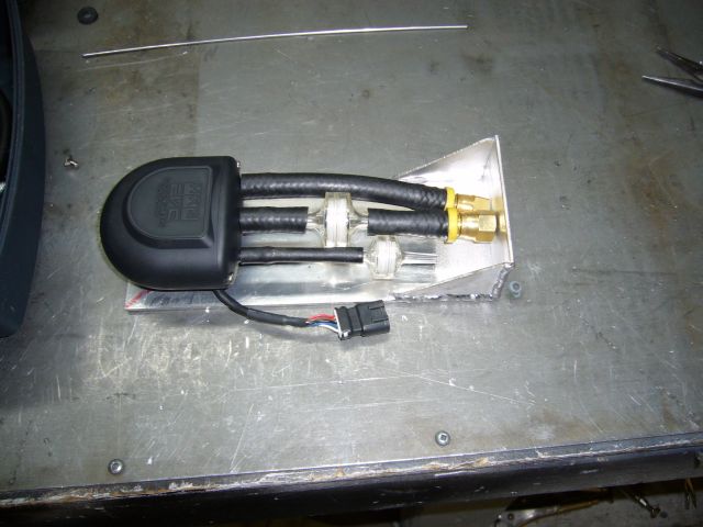
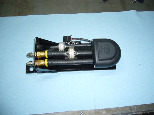
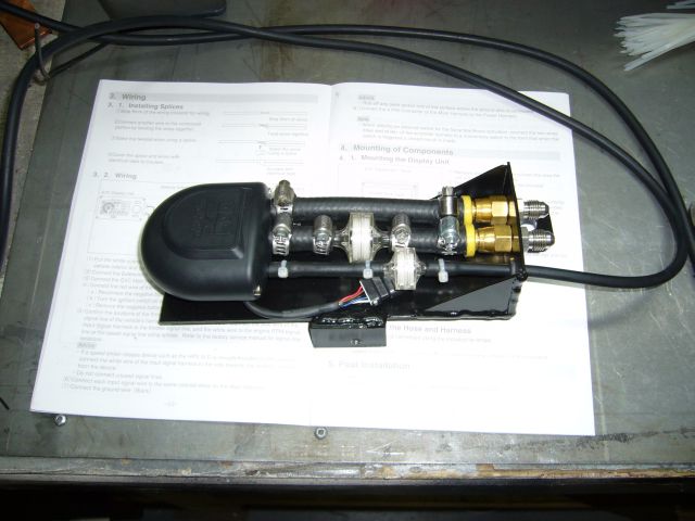
After bolting the solenoid to the bracket I mocked up the hoses so that I would know where to drill the holes for the remaining fittings. The idea is to make this its own little module that just bolts up to the car somewhere out of harms way. Boost solenoids are sensitive to heat and should be kept well away from the turbo and exhaust.
We begin where we left off last year; the installation of the rear strut bar. As detailed in the last thread, the strut bar was fabricated from 6061 aluminum as a first project after purchasing a TIG welder.
Since I installed the GT40R in 2007, I had been running on the 0.9 bar wastegate spring. Consequently the car made 13 PSI almost exactly. Even though the turbo is falling asleep at this pressure, the car managed to put down 392 RWHP on the dyno. A little more tuning after that to smooth out the top end and midrange of the map put the car at around 420 RWHP (measured on my calibrated butt dyno). Not too shabby at all, but a little more boost was needed to wake up the turbo and also eliminate some lag as the wastegate started to crack open before full boost was reached. I chose the HKS EVC 6 boost controller because it is a closed loop electronic boost controller with a load of useful features. Of course, what I mostly wanted was an electronic "dial a boost" that would simply make the pressure I set it too without a lot of tweaking or manually editing solenoid duty cycles. As the ECV 6 has two boost settings (well, technically 3 if you count scramble boost) I planned to have the low boost set at 14 PSI, and then the high boost set at whatever results in 500 RWHP.
Before all the fun though, the controller must be installed. My existing wastegate line is braided stainless with AN fittings, so I needed to adapt the lame nipples HKS put on the solenoid (really a stepper motor) to NPT fittings or AN flares. Seriously HKS, this is a $600+ boost controller, is it too much to ask for NPT ports instead of plastic nipples? As it turns out, a friend had come back from the hydraulic store with some Push-Lock -4 hose barbs which fit the HKS supplied hose perfectly, so I grabbed two and mocked up the assembly.
A bracket was needed to mount the solenoid assembly to the car, so I began fabricating one out of some 1/16" aluminum sheet.
Here is the bracket fully welded with the solenoid mounting position and holes marked.
After bolting the solenoid to the bracket I mocked up the hoses so that I would know where to drill the holes for the remaining fittings. The idea is to make this its own little module that just bolts up to the car somewhere out of harms way. Boost solenoids are sensitive to heat and should be kept well away from the turbo and exhaust.
Thread Starter
Joined: Feb 2001
Posts: 29,798
Likes: 128
From: London, Ontario, Canada
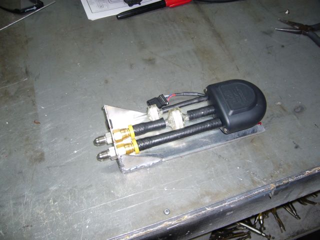
Once the holes were drilled I screwed some -4 male on male fittings into the Push-Lock barbs. This locked the hoses to the vertical section of the bracket as there was just enough space between the -4 fitting and barbs for the sheet aluminum to fit. I also installed a small rubber grommet in the remaining hole to protect the controllers vacuum line.
I ended up having to trim the radiator/headlight crossmember a little to fit the solenoid assembly where I wanted it to go, but aside from that it was a simple matter of welding on two 1/4" tabs to allow it to be bolted to existing holes on the car.
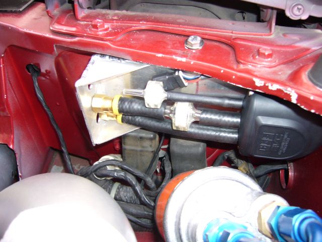
Another view shows how the solenoid assembly tucks under the rad support for protection and to minimize the useful space it takes up.
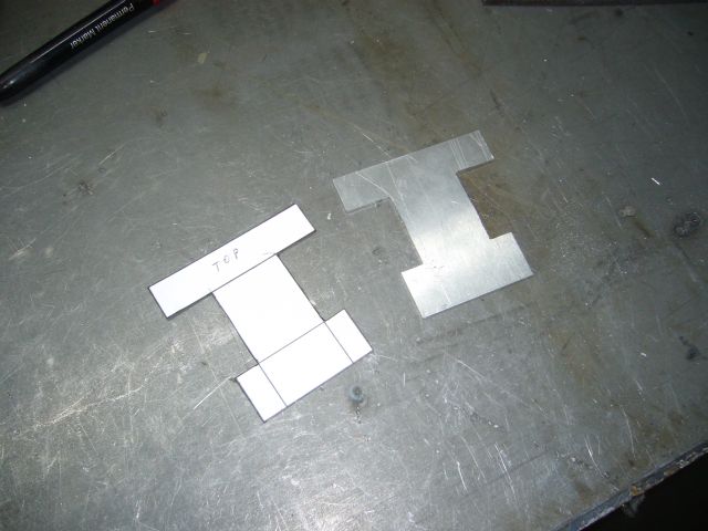
I pulled the solenoid bracket apart for painting and while alternating paint coats, started making a bracket to support the controller itself. I didn't want it stuck to the dash because I planned to set-and-forget the controller and didn't always want it in my field of view. So I decided to mount it to the interior of the glove box door on a small bracket. The first step in creating this bracket was to make a paper template.
Then I cut the bracket out on the band saw and finished the edges manually with a file.
I ended up having to trim the radiator/headlight crossmember a little to fit the solenoid assembly where I wanted it to go, but aside from that it was a simple matter of welding on two 1/4" tabs to allow it to be bolted to existing holes on the car.
Another view shows how the solenoid assembly tucks under the rad support for protection and to minimize the useful space it takes up.
I pulled the solenoid bracket apart for painting and while alternating paint coats, started making a bracket to support the controller itself. I didn't want it stuck to the dash because I planned to set-and-forget the controller and didn't always want it in my field of view. So I decided to mount it to the interior of the glove box door on a small bracket. The first step in creating this bracket was to make a paper template.
Then I cut the bracket out on the band saw and finished the edges manually with a file.
Thread Starter
Joined: Feb 2001
Posts: 29,798
Likes: 128
From: London, Ontario, Canada
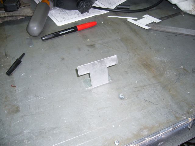
The bracket was then finished off with a slight bend in the sheet metal brake. This is so that when the glove box door was opened, the controller would face the driver.
By then the paint on the solenoid bracket was dry so final assembly on that part took place.
I then mounted the bracket for the display to the inside of the glove box door. This necessitated disassembling the door to access the other side of the black plastic backing. Two machine screws and wide washers were used to secure the mounting bracket. At the same time, I began running the wires for the controller. The controller requires a standard power and ground connection which I just supplied via an extra fuse on my aux fuse panels. Additionally it wants an RPM input (took that from the tach input at the instrument cluster) and a TPS input (I tapped into the TPS signal line at the Microtech harness). The line out into the engine bay for the solenoid exits through the harness grommet and follows along the frame rail to the front of the car.
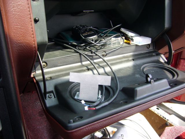
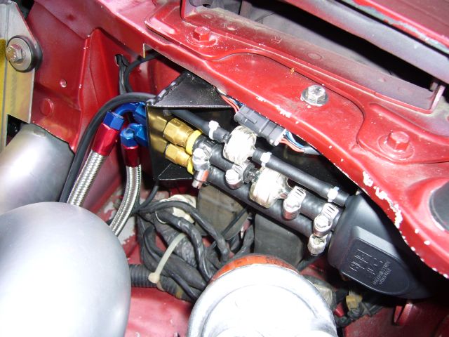
Oops, I almost forgot this picture which shows how the vacuum line for the controller passes through the grommet. You can also see that I clamped all the hoses for good measure. I had originally intended to use crimps to secure them, but realized that I might have to replace those little plastic filters some day so I settled for lame worm gear hose clamps.
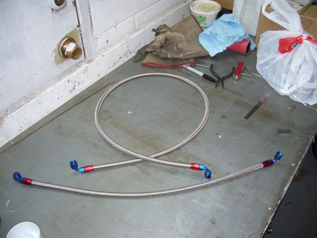
Because it really sucks when wastegate control lines blow off under boost, I had already used braided stainless line with AN fittings to connect the wastegate to a boost source. Since there were a few more lines to run for the boost controller, I assembled them with -4 braided stainless to match what was already used. I've said it before and I'll say it again: working with -4 braided stainless line sucks! The tips of my fingers were shredded afterwards but I was able to assemble these with a minimum of swearing.
By then the paint on the solenoid bracket was dry so final assembly on that part took place.
I then mounted the bracket for the display to the inside of the glove box door. This necessitated disassembling the door to access the other side of the black plastic backing. Two machine screws and wide washers were used to secure the mounting bracket. At the same time, I began running the wires for the controller. The controller requires a standard power and ground connection which I just supplied via an extra fuse on my aux fuse panels. Additionally it wants an RPM input (took that from the tach input at the instrument cluster) and a TPS input (I tapped into the TPS signal line at the Microtech harness). The line out into the engine bay for the solenoid exits through the harness grommet and follows along the frame rail to the front of the car.
Oops, I almost forgot this picture which shows how the vacuum line for the controller passes through the grommet. You can also see that I clamped all the hoses for good measure. I had originally intended to use crimps to secure them, but realized that I might have to replace those little plastic filters some day so I settled for lame worm gear hose clamps.
Because it really sucks when wastegate control lines blow off under boost, I had already used braided stainless line with AN fittings to connect the wastegate to a boost source. Since there were a few more lines to run for the boost controller, I assembled them with -4 braided stainless to match what was already used. I've said it before and I'll say it again: working with -4 braided stainless line sucks! The tips of my fingers were shredded afterwards but I was able to assemble these with a minimum of swearing.
Thread Starter
Joined: Feb 2001
Posts: 29,798
Likes: 128
From: London, Ontario, Canada
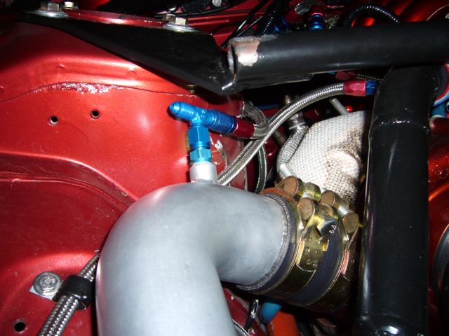
The controller needs a supply of pressurized air so I just added a T fitting to the boost source currently used for the wastegate. This required changing the fitting on the line feeding the wastegate from a 90 degree to a straight end.
Then it was just a matter of connecting the lines up. First, the connection to the boost source was made.
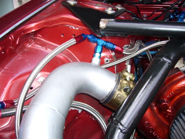
Then both lines (one from the boost source, one out to the wastegate) were connected to the solenoid.
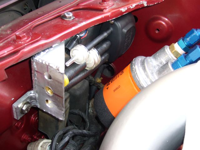
I ran the lines and harness along the frame rail. The air line to the wastegate connected to the top port via a M12 to -4 adapter fitting. The harness went along the firewall before entering through the wiring harness boot.
Now that the controller was fully installed it was time for the software setup. Powering on the system, I checked for smoke (there was little to none ) and then ran through the initial setup procedure to set the max standard boost level (the amount of boost the car makes naturally), wastegate type, and target boost levels (the high and low settings you want). As it turns out, this would cause some confusion. I initially set the max standard boost to 13 PSI as I was running a 13 PSI spring and my boost gauge always indicated that amount of boost. This was to be a problem.
The following Saturday I went out into the country with the intention to dial in the controller. But no matter what I did, the car always made between 12.3 and 12.6 PSI. Confused, I checked every setting I could. It didn't matter what the gain was set to, or the boost level, it would always make just under 13 PSI.
The following day I posted to the Single Turbo forum for help but didn't get much advice. It seems that few people were running the EVC 6. So I called HKS USA but had to leave a message on their machine. Imagine my surprise when they called be back two hours later! I was told by a very helpful tech support chick that the maximum standard boost is an absolutely critical setting. Unless the controller sees that pressure, it will never activate! Well, damn. As my car was making between 12.3 and 12.6 PSI, the controller never saw the 13 PSI I had set as the standard boost and never activated. Major kudos to HKS for returning my message long distance at their expense.
A few days later I reset the controller to factory defaults but this time set the max standard boost to 12.2 PSI. And wouldn't you know it, the controller started working. I set the low boost setting to 14 PSI, and after a few runs the car was holding 14 PSI steadily. After setting the high boost to 16 PSI and making a quick tune to that area of the fuel map, the car was pulling 16 PSI with no issues.
Let me tell you, there is a BIG difference between 13 and 16 PSI on a GT40R. My guess is about 100HP of fun was added to the car, but I didn't get a chance to go to the dyno. Read on...
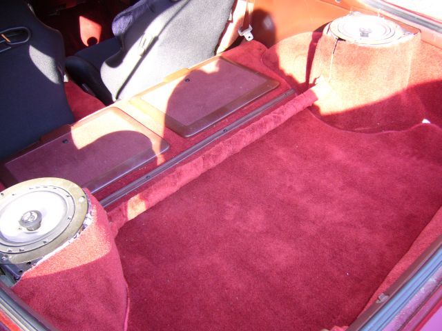
But before we get to that story, we'll start another fabrication project. Somewhere on my fuel tank is a small pinhole leak. It is on the top, in a location that never results in any spilled fuel but does result in an odor of gasoline hanging around the car. It has annoyed me for years. Additionally, when fuel is down to around a quarter of tank, hard cornering and rapid acceleration caused the fuel pump to suck air. In a few instances this was enough to cause fuel pressure to fall to nothing, causing the car to detonate due to the lean conditions produced. This was obviously a situation that needed to be corrected with the addition of a fuel sump before I was checking my mufflers for apex seals. Finally, I just wanted more fuel capacity. Getting 10 MPG in the city means visiting a gas station far too often.
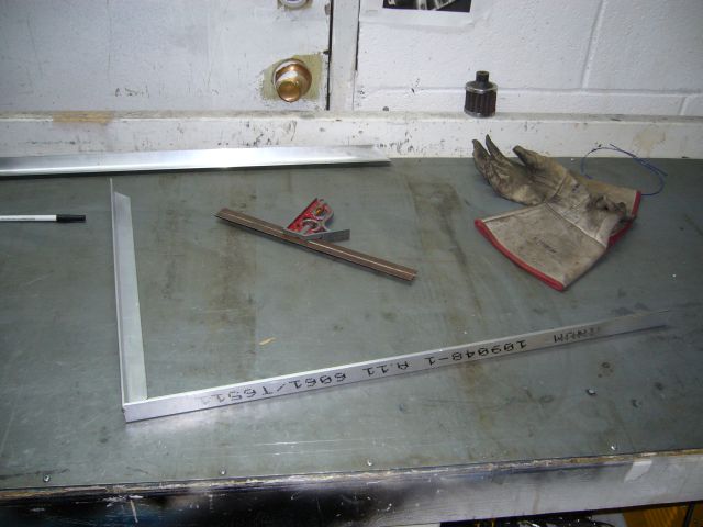
After looking at my options (a commercial fuel cell, sumping the stock tank) I decided to build a fuel tank from scratch, so I started by making a frame.
Then it was just a matter of connecting the lines up. First, the connection to the boost source was made.
Then both lines (one from the boost source, one out to the wastegate) were connected to the solenoid.
I ran the lines and harness along the frame rail. The air line to the wastegate connected to the top port via a M12 to -4 adapter fitting. The harness went along the firewall before entering through the wiring harness boot.
Now that the controller was fully installed it was time for the software setup. Powering on the system, I checked for smoke (there was little to none
) and then ran through the initial setup procedure to set the max standard boost level (the amount of boost the car makes naturally), wastegate type, and target boost levels (the high and low settings you want). As it turns out, this would cause some confusion. I initially set the max standard boost to 13 PSI as I was running a 13 PSI spring and my boost gauge always indicated that amount of boost. This was to be a problem.The following Saturday I went out into the country with the intention to dial in the controller. But no matter what I did, the car always made between 12.3 and 12.6 PSI. Confused, I checked every setting I could. It didn't matter what the gain was set to, or the boost level, it would always make just under 13 PSI.
The following day I posted to the Single Turbo forum for help but didn't get much advice. It seems that few people were running the EVC 6. So I called HKS USA but had to leave a message on their machine. Imagine my surprise when they called be back two hours later! I was told by a very helpful tech support chick that the maximum standard boost is an absolutely critical setting. Unless the controller sees that pressure, it will never activate! Well, damn. As my car was making between 12.3 and 12.6 PSI, the controller never saw the 13 PSI I had set as the standard boost and never activated. Major kudos to HKS for returning my message long distance at their expense.
A few days later I reset the controller to factory defaults but this time set the max standard boost to 12.2 PSI. And wouldn't you know it, the controller started working. I set the low boost setting to 14 PSI, and after a few runs the car was holding 14 PSI steadily. After setting the high boost to 16 PSI and making a quick tune to that area of the fuel map, the car was pulling 16 PSI with no issues.
Let me tell you, there is a BIG difference between 13 and 16 PSI on a GT40R. My guess is about 100HP of fun was added to the car, but I didn't get a chance to go to the dyno. Read on...
But before we get to that story, we'll start another fabrication project. Somewhere on my fuel tank is a small pinhole leak. It is on the top, in a location that never results in any spilled fuel but does result in an odor of gasoline hanging around the car. It has annoyed me for years. Additionally, when fuel is down to around a quarter of tank, hard cornering and rapid acceleration caused the fuel pump to suck air. In a few instances this was enough to cause fuel pressure to fall to nothing, causing the car to detonate due to the lean conditions produced. This was obviously a situation that needed to be corrected with the addition of a fuel sump before I was checking my mufflers for apex seals. Finally, I just wanted more fuel capacity. Getting 10 MPG in the city means visiting a gas station far too often.
After looking at my options (a commercial fuel cell, sumping the stock tank) I decided to build a fuel tank from scratch, so I started by making a frame.
Thread Starter
Joined: Feb 2001
Posts: 29,798
Likes: 128
From: London, Ontario, Canada
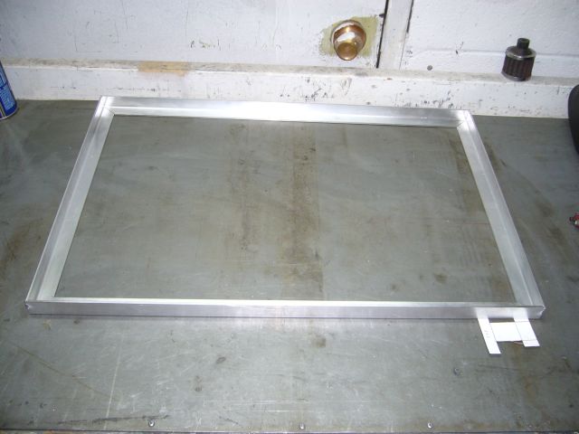
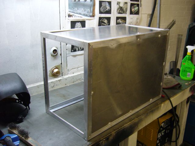
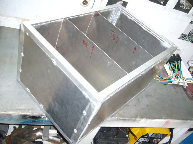
My thought was that custom aluminum fuel tanks can be subject to cracking, so it made sense to build a frame to support the tank and then simply close in the sides with sheet metal. This seemed like a good idea at first, but as I started working on the tank, it began to reveal its flaws. Here is the complete bottom of the frame, made from 1/8" 1x1 aluminum angle.
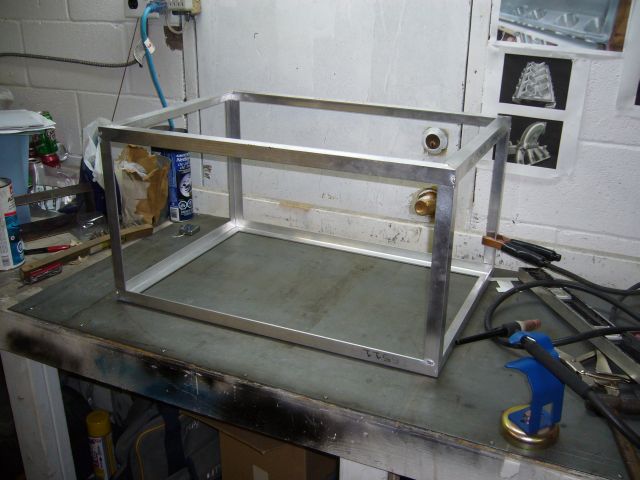
Another frame for the top was created in the same way as the bottom, and then the vertical corner pieces were cut.
I tacked the corner pieces very loosely so that it would be easy to line everything up square when the top was tacked into place.
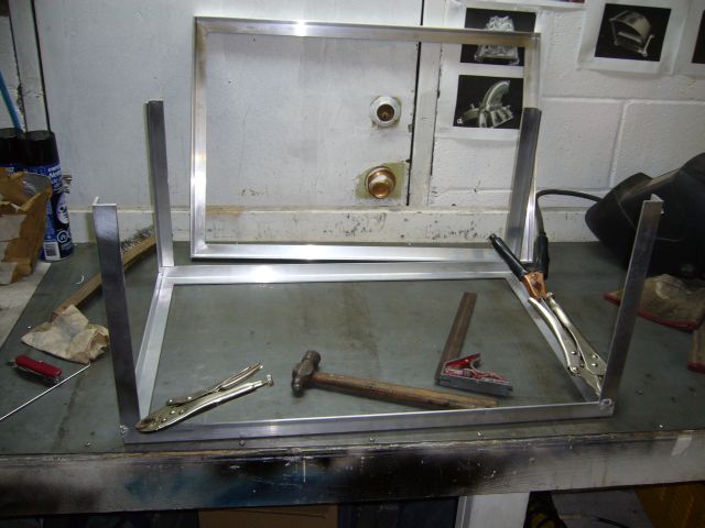
The top of the frame was then tacked on, with a considerable amount of measuring after each tack to ensure it would end up straight. The dimensions of this tank are one inch bigger on every side as compared to the stock tank. The stock steel tank actually has a crimp around the entire circumference, rounded corners and some large indented areas on the top to make room for things like the pump flange and filler tube. My tank is completely square and with the extra inch on all sides, calculated out to hold 109 litres of fuel! Some volume will be lost when the filler neck is added, but 100 litres is a hell of a lot more fuel then the stock 70 (65?) litre tank. The best part is that even with the increase in dimensions, the tank still fits in the stock location as there is a considerable amount of space.
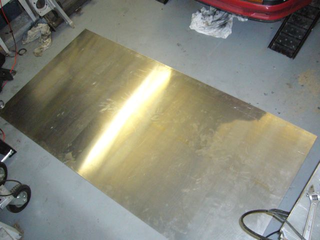
With the basic frame complete, I had a 8' x 4' sheet of 1/8" 6061 aluminum delivered from the local metal store. This would provide plenty of material for the sides of the tank.
Another frame for the top was created in the same way as the bottom, and then the vertical corner pieces were cut.
I tacked the corner pieces very loosely so that it would be easy to line everything up square when the top was tacked into place.
The top of the frame was then tacked on, with a considerable amount of measuring after each tack to ensure it would end up straight. The dimensions of this tank are one inch bigger on every side as compared to the stock tank. The stock steel tank actually has a crimp around the entire circumference, rounded corners and some large indented areas on the top to make room for things like the pump flange and filler tube. My tank is completely square and with the extra inch on all sides, calculated out to hold 109 litres of fuel! Some volume will be lost when the filler neck is added, but 100 litres is a hell of a lot more fuel then the stock 70 (65?) litre tank. The best part is that even with the increase in dimensions, the tank still fits in the stock location as there is a considerable amount of space.
With the basic frame complete, I had a 8' x 4' sheet of 1/8" 6061 aluminum delivered from the local metal store. This would provide plenty of material for the sides of the tank.
Thread Starter
Joined: Feb 2001
Posts: 29,798
Likes: 128
From: London, Ontario, Canada
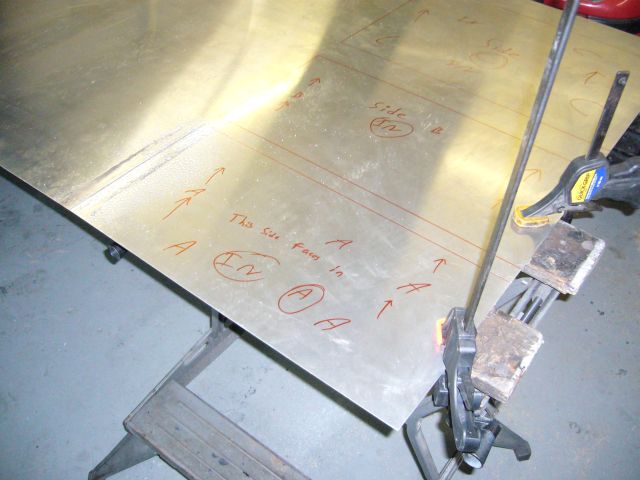
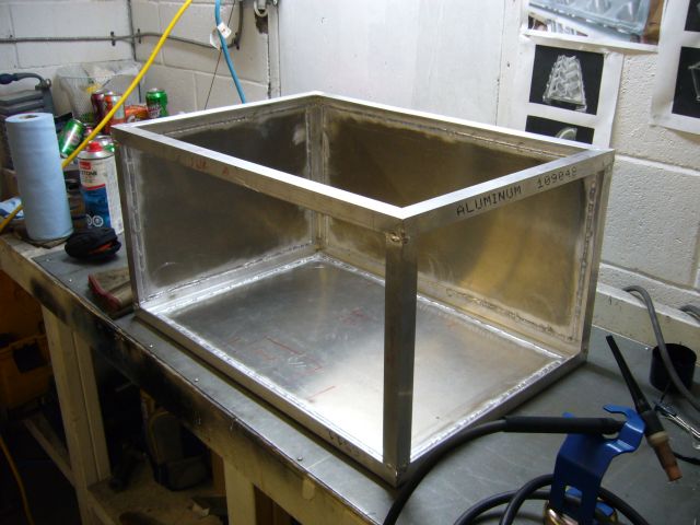
The tacked up frame was used to trace out each side piece on the aluminum sheet and then each one was clearly marked as to where it went before it was cut out with a jigsaw. It took a good spray of cutting oil to keep the cut smooth and prevent the blade from clogging but overall it was a pleasant (though time consuming) process cutting out all the sides.
Each side was test fitted after being cut. A little filing here and there was necessary since the panels were being cut by hand but overall, they fit snugly in place.
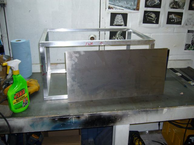
When all the sides were cut and fitted, it was time to start tacking them in place.
I tacked three sides in place after thoroughly cleaning the mating surfaces.
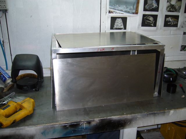
Then the three sides were welded fully inside the tank. I decided to weld the insides as well as the outsides to keep welding stresses from cracking the joint but this started to show the disadvantages of my frame-based design; it creates an assload of welding. I think that I created about 8 hours of unnecessary welding by skinning a frame instead of just making the whole tank from sheet metal, but it is quite strong as a consequence.
Each side was test fitted after being cut. A little filing here and there was necessary since the panels were being cut by hand but overall, they fit snugly in place.
When all the sides were cut and fitted, it was time to start tacking them in place.
I tacked three sides in place after thoroughly cleaning the mating surfaces.
Then the three sides were welded fully inside the tank. I decided to weld the insides as well as the outsides to keep welding stresses from cracking the joint but this started to show the disadvantages of my frame-based design; it creates an assload of welding. I think that I created about 8 hours of unnecessary welding by skinning a frame instead of just making the whole tank from sheet metal, but it is quite strong as a consequence.
Thread Starter
Joined: Feb 2001
Posts: 29,798
Likes: 128
From: London, Ontario, Canada
With three sides fully welded and the frame very rigid at this point, I started tacking the remaining sides in place. The frame did move a little bit during welding as expected, so a little more fitting was necessary to make the next few panels fit.
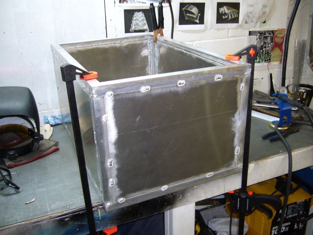
Another few hours behind the welding torch (and a lot of sunburn on my neck!) and the inside was fully welded. It was actually a more pleasant process then I thought, mainly because all of the welds were straight. But the reflection of the UV from the aluminum found every little crack in my protective clothing and I had localized sunburns over all exposed skin. Unfortunately, as the amount of welding increased, so did the distortion of the metal.
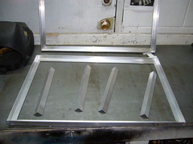
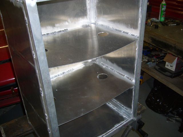
All tanks need baffles to stop fuel from sloshing around inside so the next task was to cut a set of baffles from the same 1/8" aluminum the rest of the tank was made from. I decided to go with two baffles, splitting the tank into 3 parts.
Fuel does need to flow between the baffles so aside from fitting them only loosely at the sides of the tank, I drilled several holes in each with a 2" hole saw. The hole at the bottom left is to be positioned near the sump with the idea that fuel will tend to flow towards the back of the tank and make its way into the sump.
Welding the baffles into place was a bit of bitch due to limited space and odd angles. I had to get a short cap for the back of my torch and even then it was quite frustrating. They did warp a bit during welding as you can see because the heat got away from me a bit. Well it would have been nice to keep them straight, the warp is only aesthetic and soon to be closed inside the tank never to be seen again when the top is welded into place.
Another few hours behind the welding torch (and a lot of sunburn on my neck!) and the inside was fully welded. It was actually a more pleasant process then I thought, mainly because all of the welds were straight. But the reflection of the UV from the aluminum found every little crack in my protective clothing and I had localized sunburns over all exposed skin. Unfortunately, as the amount of welding increased, so did the distortion of the metal.
All tanks need baffles to stop fuel from sloshing around inside so the next task was to cut a set of baffles from the same 1/8" aluminum the rest of the tank was made from. I decided to go with two baffles, splitting the tank into 3 parts.
Fuel does need to flow between the baffles so aside from fitting them only loosely at the sides of the tank, I drilled several holes in each with a 2" hole saw. The hole at the bottom left is to be positioned near the sump with the idea that fuel will tend to flow towards the back of the tank and make its way into the sump.
Welding the baffles into place was a bit of bitch due to limited space and odd angles. I had to get a short cap for the back of my torch and even then it was quite frustrating. They did warp a bit during welding as you can see because the heat got away from me a bit. Well it would have been nice to keep them straight, the warp is only aesthetic and soon to be closed inside the tank never to be seen again when the top is welded into place.
Trending Topics
Thread Starter
Joined: Feb 2001
Posts: 29,798
Likes: 128
From: London, Ontario, Canada
Let's take a quick momentary break from the tank for a quick story. This was the first year in a while where I was able to drive the car in the early spring. The winter ended quickly enough that I actually took the car out of the garage in late March, replaced the rear calipers (one was leaking) and then had it on the road. It was about a month later (just before the Easter weekend) that I blew the first transmission. You can read the full story in this thread but here are the highlights.
One afternoon I was running across the city to get to the post office before 5PM. One of the main cross streets turns into an expressway so the speed limit goes from 60 (KM/H) to 100. As the light turned green I was stuck behind some douche in a Camry that didn't seem to understand that going 50 KM/H in the left lane of a 100 zone is a bad thing. With the big diesel riding my butt so close I could see the herpes on the driver's lips, I signalled to switch lanes.
Of course, just as I was pulling out, the guy driving the diesel *****-extension behind me thought it would be a good idea to move lanes as well and punch his throttle. I'm thinking "WTF?". So I dropped it into third, went WOT and unleashed the beast. I had very little room because my off ramp was the next one otherwise I would have been a little more responsible. Missing exits also means a round trip through prime traffic jam area.
Coming up on about 5500 RPM there was a noise that was a combination grinding-clunking-banging, at which point the car stopped accelerating. I tried 3rd again...no dice. Nothing in 2nd either. Finding 4th, I took my ramp and luckily had all green lights to a local parking lot, where a tow truck met me and towed me home.
I had a spare transmission which I quickly swapped in place the following weekend, then pulled apart the blown unit a few days later. The damage was quite impressive:

Looks like I stripped the input shaft and the cluster shaft input gear. I was not entirely surprised as the transmission did pick up a bit of a whine after an evening at the track last year, and some more tuning had really smoothed out the fuel map and improved the midrange of the car considerably. It was just a matter of time before the NA transmission would give up on life.

So with the transmission replaced, I continued to drive the car for the rest of the summer.
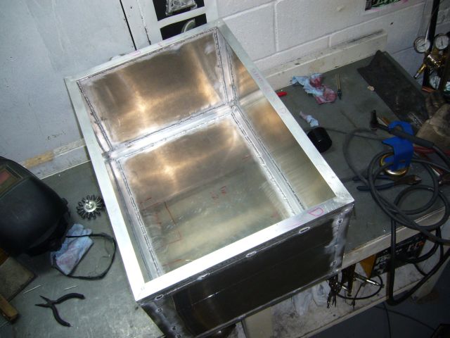
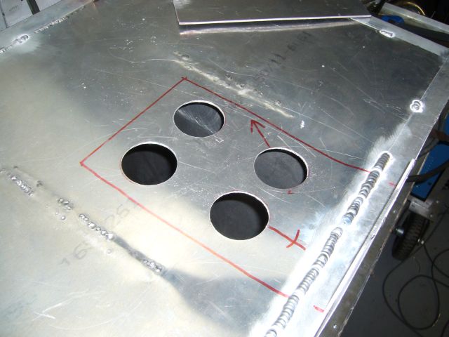
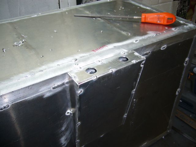
Back to the tank, it was time to start working on the fuel sump. I first welded up the section of the outer seam that would be covered by the sump and then measured the area. The vertical plate you see in the bottom right of the image is the rear vertical section of the sump. It was tacked into place after I decided how big of a sump I wanted. The four circles within the sump area will allow fuel from the main tank into the sump. After reading some tank fabrication articles, it seems that many builders just drill large holes instead of cutting the entire area out. The thought is that the metal lip left by the holes will help prevent fuel from sloshing out of the sump. This seemed like a good idea to me.
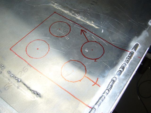
Next, I just drilled the holes out with a hole saw.
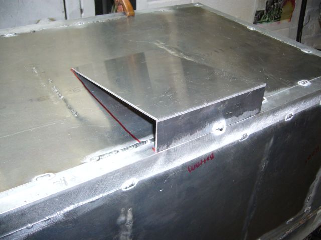
The bottom half of the sump was then cut and test fitted.
One afternoon I was running across the city to get to the post office before 5PM. One of the main cross streets turns into an expressway so the speed limit goes from 60 (KM/H) to 100. As the light turned green I was stuck behind some douche in a Camry that didn't seem to understand that going 50 KM/H in the left lane of a 100 zone is a bad thing. With the big diesel riding my butt so close I could see the herpes on the driver's lips, I signalled to switch lanes.
Of course, just as I was pulling out, the guy driving the diesel *****-extension behind me thought it would be a good idea to move lanes as well and punch his throttle. I'm thinking "WTF?". So I dropped it into third, went WOT and unleashed the beast. I had very little room because my off ramp was the next one otherwise I would have been a little more responsible. Missing exits also means a round trip through prime traffic jam area.
Coming up on about 5500 RPM there was a noise that was a combination grinding-clunking-banging, at which point the car stopped accelerating. I tried 3rd again...no dice. Nothing in 2nd either. Finding 4th, I took my ramp and luckily had all green lights to a local parking lot, where a tow truck met me and towed me home.
I had a spare transmission which I quickly swapped in place the following weekend, then pulled apart the blown unit a few days later. The damage was quite impressive:
Looks like I stripped the input shaft and the cluster shaft input gear. I was not entirely surprised as the transmission did pick up a bit of a whine after an evening at the track last year, and some more tuning had really smoothed out the fuel map and improved the midrange of the car considerably. It was just a matter of time before the NA transmission would give up on life.
So with the transmission replaced, I continued to drive the car for the rest of the summer.
Back to the tank, it was time to start working on the fuel sump. I first welded up the section of the outer seam that would be covered by the sump and then measured the area. The vertical plate you see in the bottom right of the image is the rear vertical section of the sump. It was tacked into place after I decided how big of a sump I wanted. The four circles within the sump area will allow fuel from the main tank into the sump. After reading some tank fabrication articles, it seems that many builders just drill large holes instead of cutting the entire area out. The thought is that the metal lip left by the holes will help prevent fuel from sloshing out of the sump. This seemed like a good idea to me.
Next, I just drilled the holes out with a hole saw.
The bottom half of the sump was then cut and test fitted.
Thread Starter
Joined: Feb 2001
Posts: 29,798
Likes: 128
From: London, Ontario, Canada
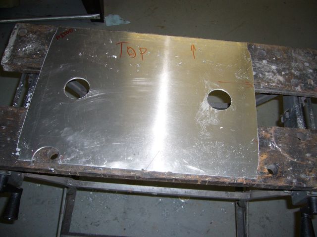
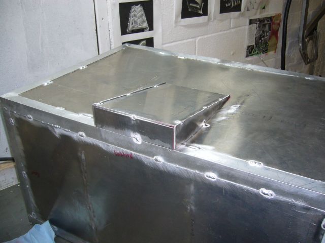
After tacking the bottom of the sump, I made paper templates for each side and then cut each side individually. I had to do this because the bottom of the tank had warped from all the welding and was no longer quite straight. Actually, quite a lot of the tank had warped and it was no longer dimensionally accurate. This happened despite welding in short bursts, controlling heat and alternating seams. The whole bottom sort of bowed inwards. I can't say that I'm very happy with the tank because of this and am considering trying to make another. If I do take that approach, I will simply have a metal shop bend up the sheet metal in a box so that all I will have to do is weld in the baffles, attach the sides, and add the sump.
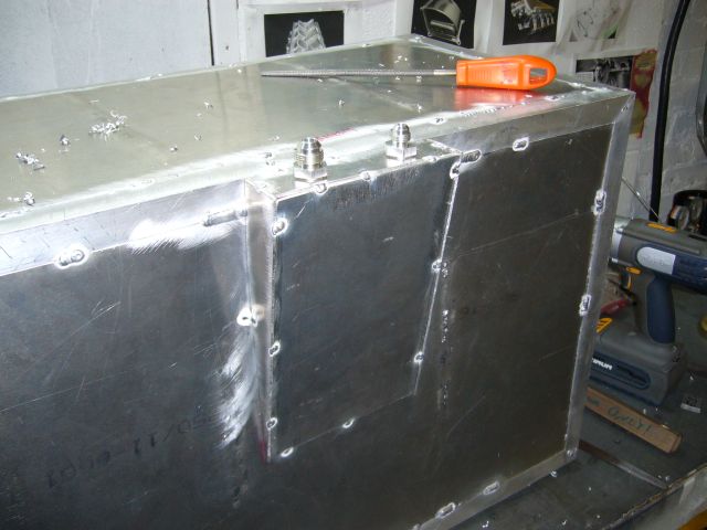
Here's a view from inside the tank at the sump, just before the top was welded in place. You can see the internal seams of the frame at the top of the image, and the baffles at either side.
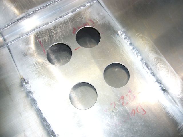
The sump has two fuel fittings; an outlet to the pump and then the inlet return fitting (from the pressure regulator). Before they can be welded into place, holes must be drilled. I used a step drill to make the odd sized holes required by the weld-in AN flares.
The fuel pump feed fitting is a -8 flare while the return to the tank is a -6 flare. The feed to the pump needs to be larger is it is on the vacuum side of the pump and thus subject to negative pressure. Having too small a hose will drastically increase the effort required by the pump to pull fuel and thus limit fuel flow.
It was finally time to fully weld the tank! This is where I finally decided that building a frame and enclosing it is the wrong way to make a fuel tank. The primary reason is that it created about four times the welding then would have been needed by directly welding the panels together. After about 6 or so hours behind the torch the tank was fully welded, I was a few bottles of shielding gas poorer, a bit sunburned and sick of working on this stupid tank.
There was, however, a certain odd satisfaction in filling the tank up with water as a leak test.
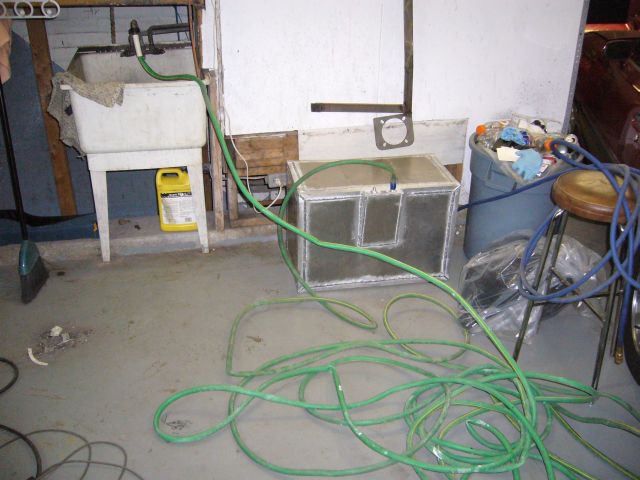
Sadly, there were a few leaks. I guess it was bound to happen, so they were marked for later repair.
So the tank (mostly) holds water, but can you spot the issue with this picture? That's right...1 litre of water is not heavy (about 2.2 LBs, actually). However, the 110 litres of water that filled this tank certainly was! The size and weight of the tank required two people to lift it up to the sink where it took 10 minutes to drain as air was blown in with the compressor.
Here's a view from inside the tank at the sump, just before the top was welded in place. You can see the internal seams of the frame at the top of the image, and the baffles at either side.
The sump has two fuel fittings; an outlet to the pump and then the inlet return fitting (from the pressure regulator). Before they can be welded into place, holes must be drilled. I used a step drill to make the odd sized holes required by the weld-in AN flares.
The fuel pump feed fitting is a -8 flare while the return to the tank is a -6 flare. The feed to the pump needs to be larger is it is on the vacuum side of the pump and thus subject to negative pressure. Having too small a hose will drastically increase the effort required by the pump to pull fuel and thus limit fuel flow.
It was finally time to fully weld the tank! This is where I finally decided that building a frame and enclosing it is the wrong way to make a fuel tank. The primary reason is that it created about four times the welding then would have been needed by directly welding the panels together. After about 6 or so hours behind the torch the tank was fully welded, I was a few bottles of shielding gas poorer, a bit sunburned and sick of working on this stupid tank.
There was, however, a certain odd satisfaction in filling the tank up with water as a leak test.
Sadly, there were a few leaks. I guess it was bound to happen, so they were marked for later repair.
So the tank (mostly) holds water, but can you spot the issue with this picture? That's right...1 litre of water is not heavy (about 2.2 LBs, actually). However, the 110 litres of water that filled this tank certainly was! The size and weight of the tank required two people to lift it up to the sink where it took 10 minutes to drain as air was blown in with the compressor.
Thread Starter
Joined: Feb 2001
Posts: 29,798
Likes: 128
From: London, Ontario, Canada
At this point I was rather sick of working on the fuel tank, so the car offered me a distraction which realigned my priorities regarding what work needs to be done.
Late in the summer, I finally got around to turning up the boost. At 16 PSI it feels like there is 100HP more to play with, but it only took 3 or so runs before the "new" transmission started making some unhappy noises. I continued to drive the car just being conscious that the transmission could leave me at the side of the road at moment. As it turns out, that is exactly what happened in mid November. Once again, you can find the full story in this thread.
One afternoon, I was out for a drive with some friends. 10 minutes out of the city we had a clear road ahead but were stuck behind a truck pulling a trailer at half the speed limit. The car ahead of me pulled out and passed, I followed by dropping it to 3rd and putting the fun pedal down. Literally exactly as ocurred the first time, the transmission tore itself apart as the engine just crossed 5,000 RPM at 14 PSI. I was treated so the same shattering-crunching-grinding-breaking noise as before, and had no gears but forth.
I was able to limp home in 4th, which was a lot of fun as I happened to hit every freaking red light as I drove through the city from the highway to my house. It was scary how during the trip the transmission started crushing rocks, yet grew more quiet as the parts self machined...
As it was so late in the season and I figured we would be seeing snow at any point (oh, how wrong I was...we only just now received snow on December the 29th), I decided to just park the car in my shop and start pulling out the dead transmission for replacement. A few weeks prior I had purchased a TII transmission locally, knowing I would be needing a replacement. While I considered several different transmission options, eventually leaning towards the T5, the price of the TII transmission was hard to beat and sometimes there is something said for just bolting something in place. While the TII unit was out at a local transmission shop getting being rebuilt (new seals, bearings, syncros) I was preparing for its installation.
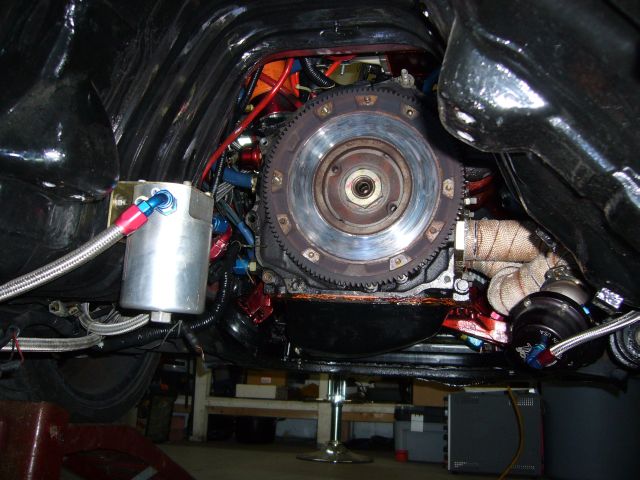
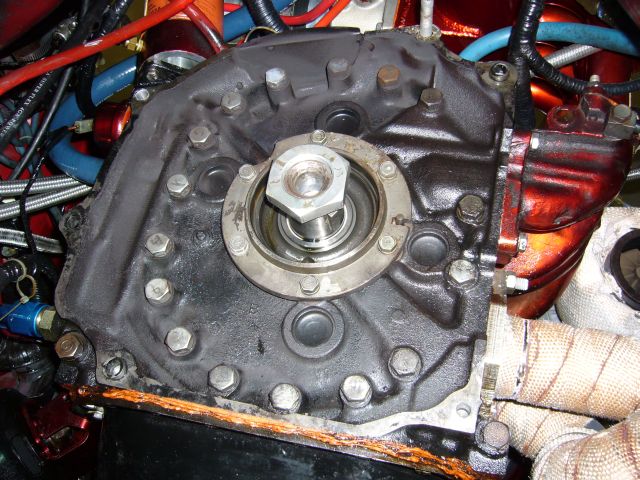
First, I pulled out the 2nd blown NA transmission. Check out this flywheel. I guess this is what happens when you drive home 50KM using only 4th gear on a copper puck-style clutch. Both the flywheel and pressure plate (not to mention the disc) are totalled.
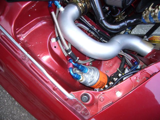
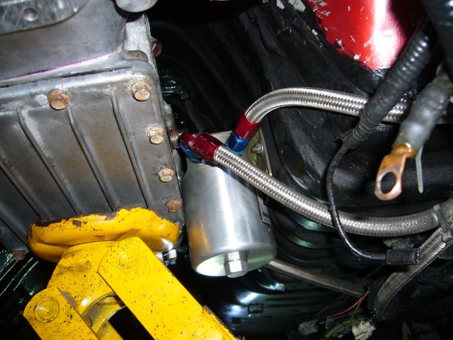
Well screw me sideways with a sandy pickle, the fuel filter is in the way of the much larger TII transmission. Or the transmission is in the way of the fuel filter, either way it sucks.
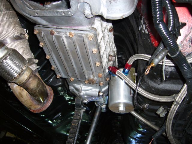
Oh, on second thought there is plenty of room for the fuel filter after the transmission is installed.
After using a torch to warm up the flywheel nut enough to release the red Loctite, the impact wrench made quick work of the nut. After that the flywheel was removed, followed by the pilot bearing and seals. While the pilot bearing and rear seal were only a few years old, it makes sense to replace them anytime the transmission is pulled just because of the pain in the *** factor of actually getting to them.
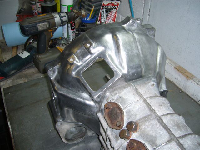
Thanks to Danny's Transmission in London (Ontario) I had a fully rebuilt TII transmission ready to go. Before it could go into the car I wanted to paint the bellhousing to match the rest of the engine. So the first step was to give it a quick polish using a wire wheel on the drill.
Late in the summer, I finally got around to turning up the boost. At 16 PSI it feels like there is 100HP more to play with, but it only took 3 or so runs before the "new" transmission started making some unhappy noises. I continued to drive the car just being conscious that the transmission could leave me at the side of the road at moment. As it turns out, that is exactly what happened in mid November. Once again, you can find the full story in this thread.
One afternoon, I was out for a drive with some friends. 10 minutes out of the city we had a clear road ahead but were stuck behind a truck pulling a trailer at half the speed limit. The car ahead of me pulled out and passed, I followed by dropping it to 3rd and putting the fun pedal down. Literally exactly as ocurred the first time, the transmission tore itself apart as the engine just crossed 5,000 RPM at 14 PSI. I was treated so the same shattering-crunching-grinding-breaking noise as before, and had no gears but forth.
I was able to limp home in 4th, which was a lot of fun as I happened to hit every freaking red light as I drove through the city from the highway to my house. It was scary how during the trip the transmission started crushing rocks, yet grew more quiet as the parts self machined...
As it was so late in the season and I figured we would be seeing snow at any point (oh, how wrong I was...we only just now received snow on December the 29th), I decided to just park the car in my shop and start pulling out the dead transmission for replacement. A few weeks prior I had purchased a TII transmission locally, knowing I would be needing a replacement. While I considered several different transmission options, eventually leaning towards the T5, the price of the TII transmission was hard to beat and sometimes there is something said for just bolting something in place. While the TII unit was out at a local transmission shop getting being rebuilt (new seals, bearings, syncros) I was preparing for its installation.
First, I pulled out the 2nd blown NA transmission. Check out this flywheel. I guess this is what happens when you drive home 50KM using only 4th gear on a copper puck-style clutch. Both the flywheel and pressure plate (not to mention the disc) are totalled.
Well screw me sideways with a sandy pickle, the fuel filter is in the way of the much larger TII transmission. Or the transmission is in the way of the fuel filter, either way it sucks.
Oh, on second thought there is plenty of room for the fuel filter after the transmission is installed.
After using a torch to warm up the flywheel nut enough to release the red Loctite, the impact wrench made quick work of the nut. After that the flywheel was removed, followed by the pilot bearing and seals. While the pilot bearing and rear seal were only a few years old, it makes sense to replace them anytime the transmission is pulled just because of the pain in the *** factor of actually getting to them.
Thanks to Danny's Transmission in London (Ontario) I had a fully rebuilt TII transmission ready to go. Before it could go into the car I wanted to paint the bellhousing to match the rest of the engine. So the first step was to give it a quick polish using a wire wheel on the drill.
Thread Starter
Joined: Feb 2001
Posts: 29,798
Likes: 128
From: London, Ontario, Canada
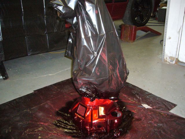
After that, 3 coats of MetalCast red and the bellhousing had a finish matching the rest of my engine bay. I did briefly consider painting the rest of the transmission silver but figured that it would get all scratched up during installation and it is under the car anyway, mostly covered by the big exhaust heat shield.
I think that's it for now. I have since installed a TII flywheel and new clutch to match. The transmission itself bolted into the car last night and tonight I am planning on taking care of the little things which are related (clutch slave, extending the wiring, shifter reinstallation, etc.).
Now I do have some more plans for the rest of the winter. I need to fix some small issues with the car that have been bothering me. A few little oil leaks, stock engine mounts and some other engine bay clutter has become more of an annoyance the more I drive the car. The front cover also needs to be pulled for installation of a TII oil pump so while I have that off, I will also be making a few adjustments to it after I (gasp!!) remove the metering oil pump. Finally, I have an LSD rear end sitting in the corner of the shop just waiting to be installed, and of course, the bloody fuel tank will actually need to be mounted on the car (as soon as I figure out how).


Junior Member
Joined: May 2009
Posts: 7
Likes: 0
From: Rodney, Ontario, Canada
Thanks for the write-up Aaron. It's great to live vicariously through your amazing mods to this car.
There's a red 2nd Gen that I saw several times over the summer just north of the 401 off Hwy 4 (Colonel Talbot Rd). Was that you?
The late start of winter in SW Ontario has been an annoyance to other folks I know who've put cars away early this year. I've opted to go the other route, tossed on 4 snows and keep driving my 88 GXL. I must admit it's nice to have the predictability of rear-wheel drive coupled with 50-50 weight distribution for a winter driver. The ground clearance isn't great though!
Keep up the great work, and the detailed write-ups. I've picked up many very helpful tips from your posts here and your website.
Thread Starter
Joined: Feb 2001
Posts: 29,798
Likes: 128
From: London, Ontario, Canada
The late start of winter in SW Ontario has been an annoyance to other folks I know who've put cars away early this year. I've opted to go the other route, tossed on 4 snows and keep driving my 88 GXL. I must admit it's nice to have the predictability of rear-wheel drive coupled with 50-50 weight distribution for a winter driver. The ground clearance isn't great though!
I don't know their exact name, but most hydraulic stores refer to them as "Push Lock" or "Twist Lock". They are just an aggressive brass nipple with a 37 degree female AN flare on the other side. The yellow plastic part is a stopper to limit how far you can push the hose on. It takes a considerable amount of effort to push the hose in place because these fittings are usually used in multi-thousand PSI hydraulic applications.

I don't know their exact name, but most hydraulic stores refer to them as "Push Lock" or "Twist Lock". They are just an aggressive brass nipple with a 37 degree female AN flare on the other side. The yellow plastic part is a stopper to limit how far you can push the hose on. It takes a considerable amount of effort to push the hose in place because these fittings are usually used in multi-thousand PSI hydraulic applications.

