
130 AMP Taurus alternator Swap


Thread Starter
Junior Member
Joined: Mar 2009
Posts: 24
Likes: 0
From: London, Ontario
130 AMP Taurus alternator Swap
So recently i have been having really bad charging issues to the point that at night if i didnt let the car run for 10 minutes with the lights off when i was done driving it would not start the next morning.
So i decided to swap the alternator and found out that a taurus alternator can be intalled withought modifiying the stock wiring.
It took me two tries to get it right simply due to incorrect material choice for the alternator adaptor bracket.
heres what i did:
the first time around i took some galvanized steel C chanel and cut it into a pattern then folded "tabs" to create the adaptor bracket.
i carefully measured the postition of the stock pully before designing the bracket. it took me about 45 mins just to plan it out and about 15 mins to acctually make it.
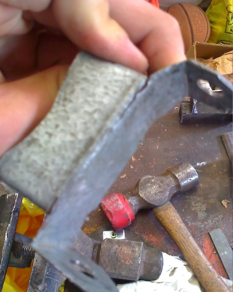
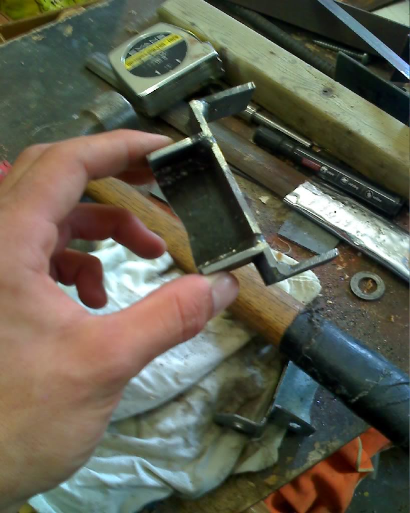
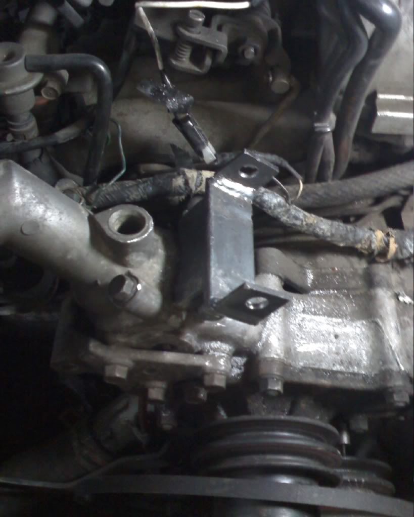
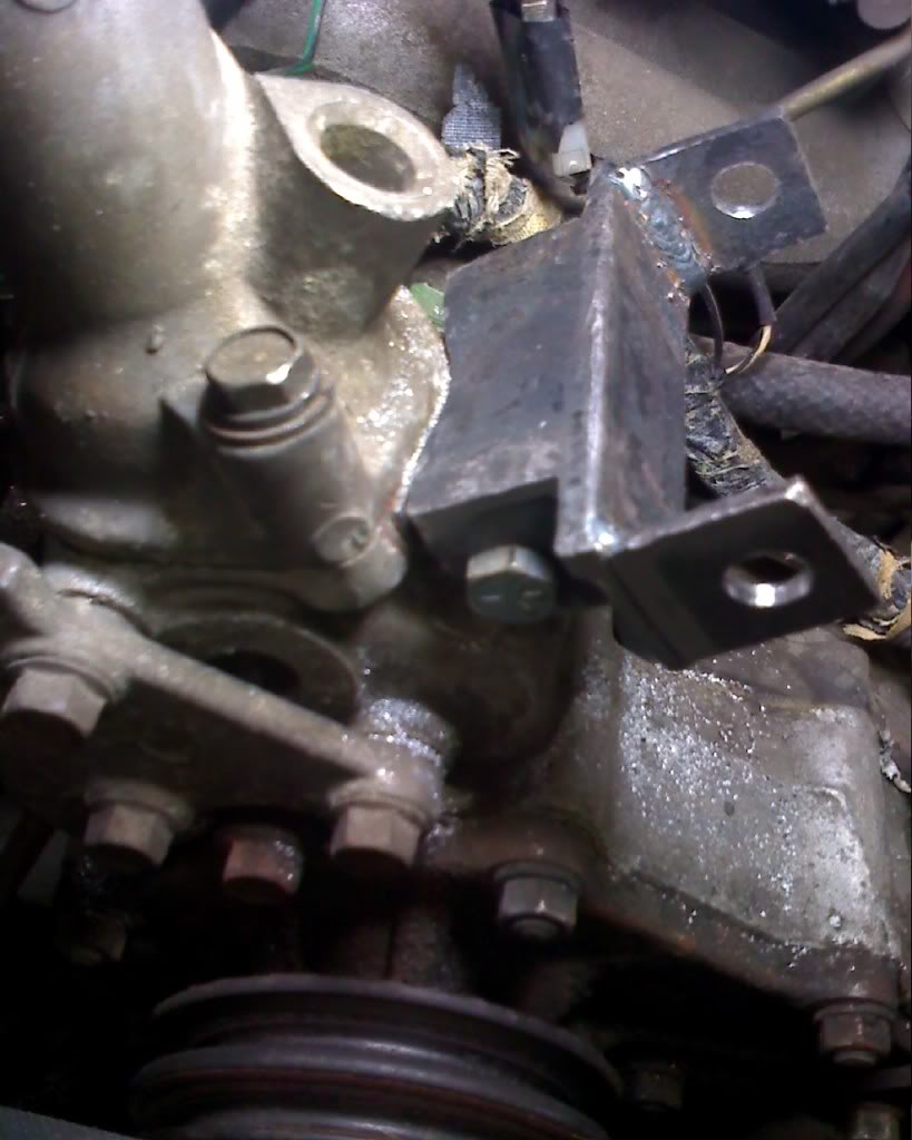
the problem with this design was that the metal itself was to thin to take the vibrations and constant tension from the belt and after about 2 1/2 months of slow deterioration i was just waiting for it to break off and create mayhem in my engine bay so i went out and got some 1/4" thick angle steel and this time i cut then welded the "tabs" this time with much better outcome. The alternator now has absolutely no movement no matter how hard u try to move it.
The wiring was relatively simple. I upgraded the main power line to the battery which was very thin with 4awg power cable
the plug on the alternator is labled with A,S,and I consecutively
I used the portion of the harnes that came with the alternator which i got from the wreckers then had tested and was good at 14.3V
The wire coming from A is connected to the stock alternator plug on the RX7 Harness to the Horizontal pin. If you are looking at it in the "T" position there is to pins one which is vertical and one Horizontal forming a T. This pin isa 12V switched source.
The vertical plug is unused.
The Wire coming from S already has a plug on the end of it ans simply plugs into the stator of the alternator.
The wire coming from I goes to a constant 12V.
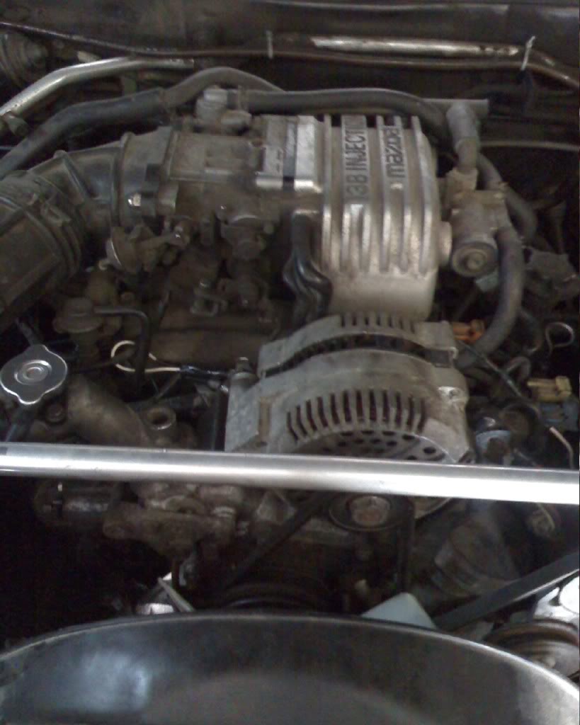
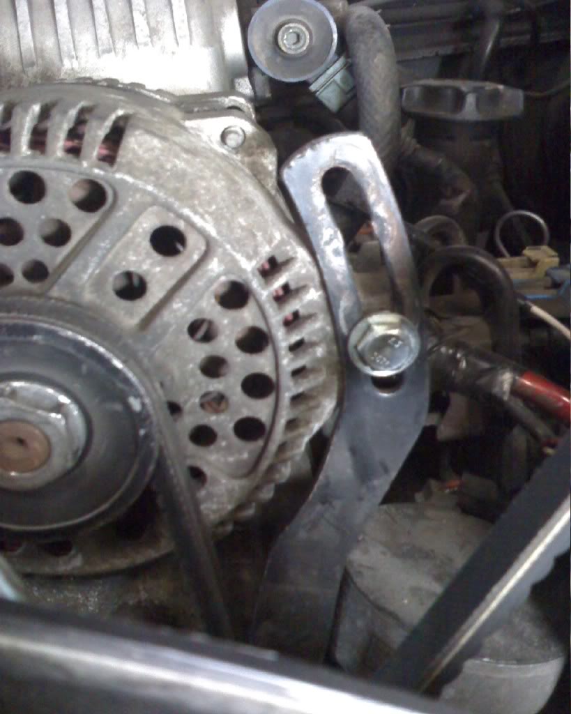
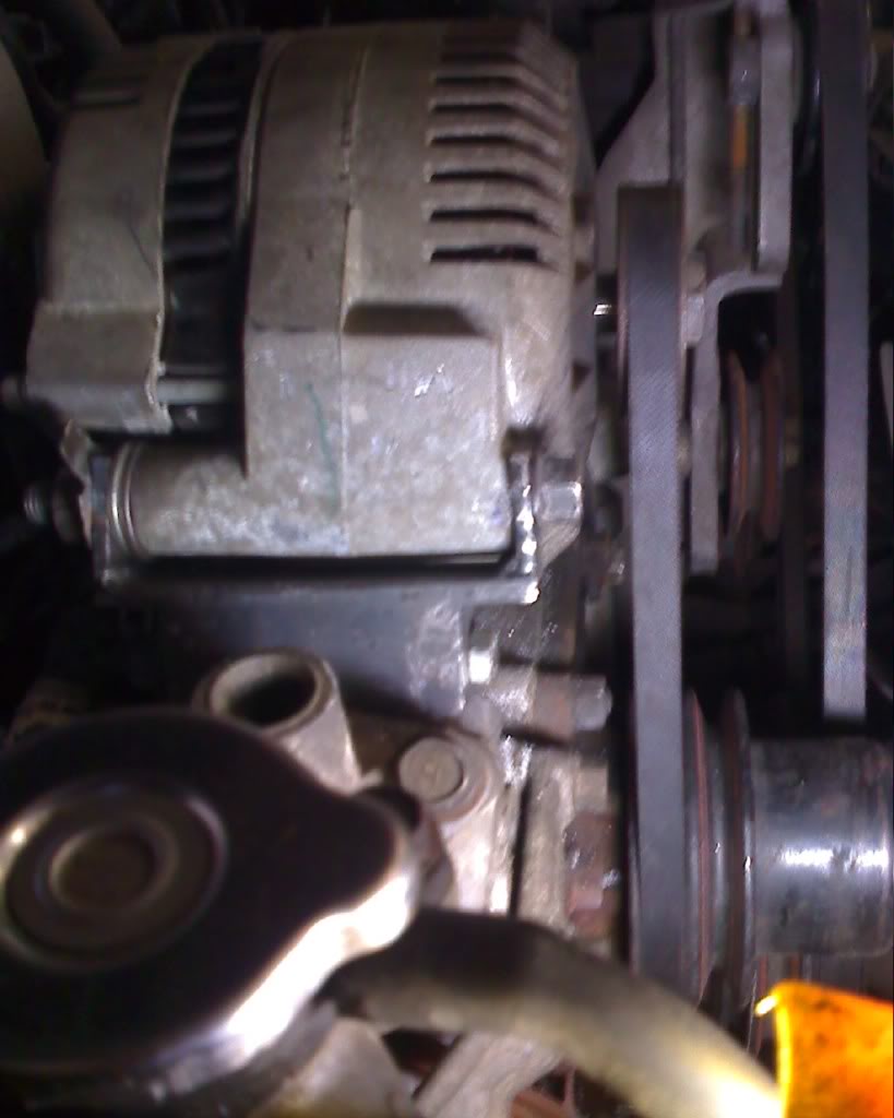
here is some pictures of how it turned out. The belt is perfectly alligned and i have been using it for about a month no with no problems at all and my volt meter is the highest i have ever seen one in an 7. Its ussually around 13 at idle and about 14 when driving and it does not drop at all with lights on and all the accessories going.
The first bracket after 2 1/2 month use ( I cant believe it held on this long!)
new bracket
new bracket and old side by side
new bracket mounted
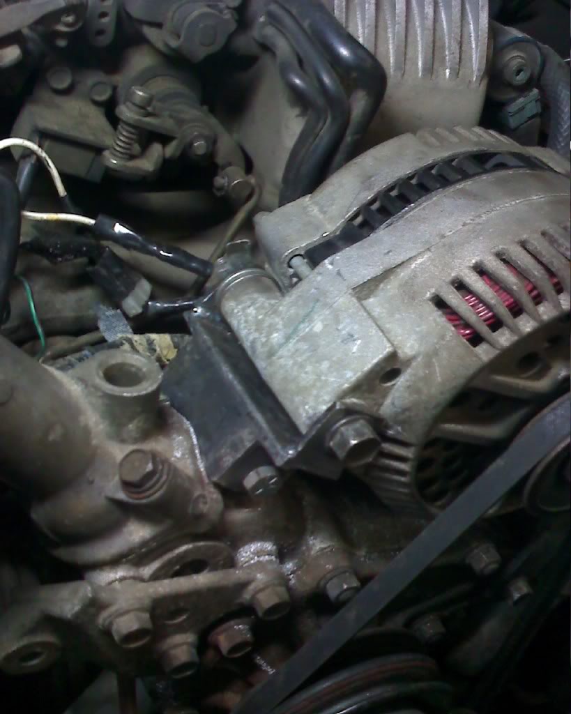
alternator going in
all done!
So i decided to swap the alternator and found out that a taurus alternator can be intalled withought modifiying the stock wiring.
It took me two tries to get it right simply due to incorrect material choice for the alternator adaptor bracket.
heres what i did:
the first time around i took some galvanized steel C chanel and cut it into a pattern then folded "tabs" to create the adaptor bracket.
i carefully measured the postition of the stock pully before designing the bracket. it took me about 45 mins just to plan it out and about 15 mins to acctually make it.
the problem with this design was that the metal itself was to thin to take the vibrations and constant tension from the belt and after about 2 1/2 months of slow deterioration i was just waiting for it to break off and create mayhem in my engine bay so i went out and got some 1/4" thick angle steel and this time i cut then welded the "tabs" this time with much better outcome. The alternator now has absolutely no movement no matter how hard u try to move it.
The wiring was relatively simple. I upgraded the main power line to the battery which was very thin with 4awg power cable
the plug on the alternator is labled with A,S,and I consecutively
I used the portion of the harnes that came with the alternator which i got from the wreckers then had tested and was good at 14.3V
The wire coming from A is connected to the stock alternator plug on the RX7 Harness to the Horizontal pin. If you are looking at it in the "T" position there is to pins one which is vertical and one Horizontal forming a T. This pin isa 12V switched source.
The vertical plug is unused.
The Wire coming from S already has a plug on the end of it ans simply plugs into the stator of the alternator.
The wire coming from I goes to a constant 12V.
here is some pictures of how it turned out. The belt is perfectly alligned and i have been using it for about a month no with no problems at all and my volt meter is the highest i have ever seen one in an 7. Its ussually around 13 at idle and about 14 when driving and it does not drop at all with lights on and all the accessories going.
The first bracket after 2 1/2 month use ( I cant believe it held on this long!)
new bracket
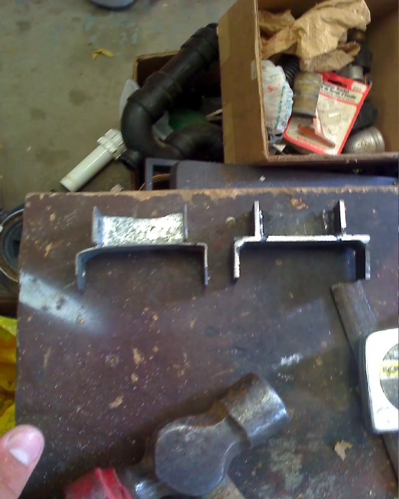
new bracket and old side by side
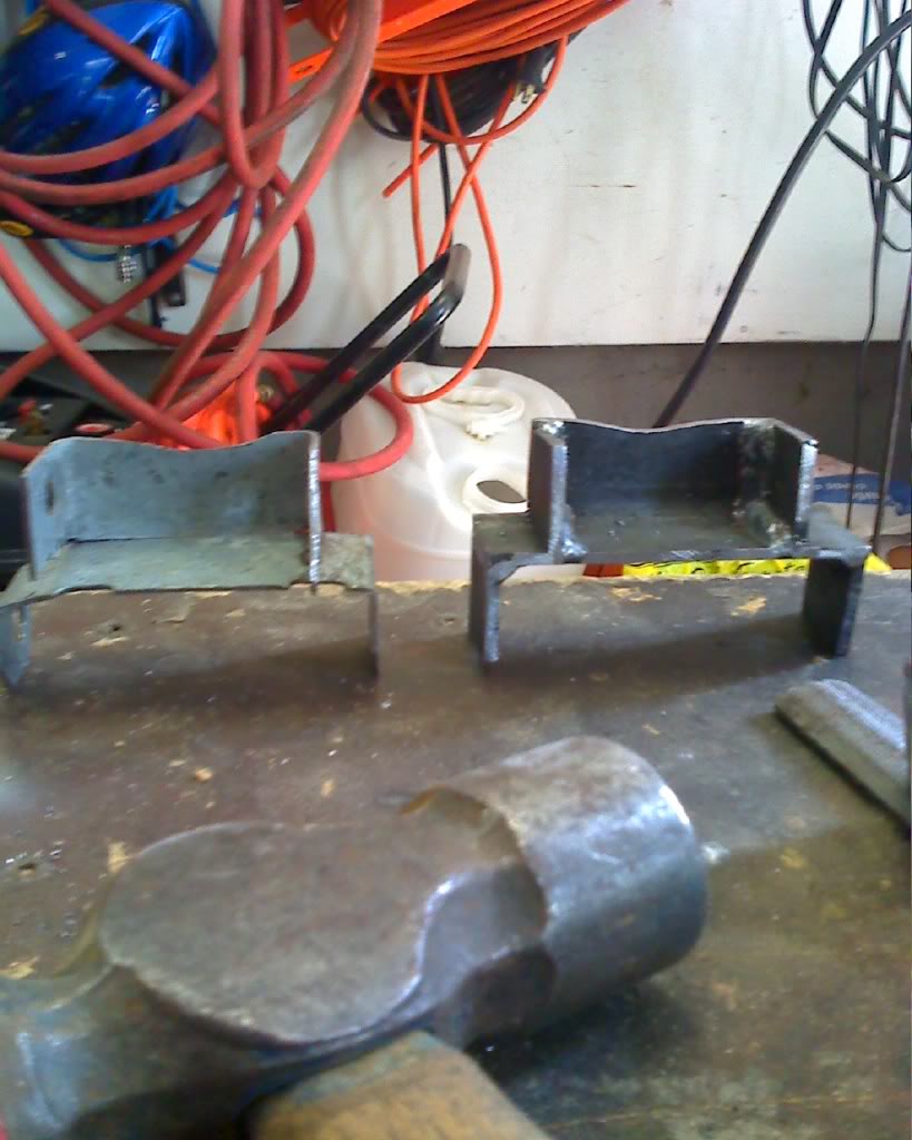
new bracket mounted
alternator going in
all done!

Joined: Apr 2005
Posts: 3,785
Likes: 30
From: And the horse he rode in on...
Thread Starter
Junior Member
Joined: Mar 2009
Posts: 24
Likes: 0
From: London, Ontario
hey thanks alot i probably wouldnt get into selling them as i dont really have the proper tools to do it lol. i used a hack saw for every cut then carefully squared everything off with a bench grinder and then i had to use a buddys welder to weld it. but if anyone is interested in making on i can give u all my measurements just pm me.
Trending Topics
Thread Starter
Junior Member
Joined: Mar 2009
Posts: 24
Likes: 0
From: London, Ontario
The alternator i have is off a 97 but i think that from 1996-1999 they are the same off the 3L motor. and i doubt there is any difference from the american one and the canadian one


Thread Starter
Junior Member
Joined: Mar 2009
Posts: 24
Likes: 0
From: London, Ontario
well im not 100% on that but the taurus it came off had a 7K redline and the alternator has a smaller diameter pully then the stock 7 one. But i have no idea what size crank pully the taurus had so im not certain on the max rpm this alt was meant to see, but i can say that i have been to the track with this alt twice and have never had any issues. my car gets redline on a regular basis and ive been using it for over 3 months now with no issues othere then the first bracket starting to fail.


Hey Jack, remember my PM? that's the about the same thing my bracket did.. So I need my bracket made of 1/4 angle steel.
Oh yeah, by the way for any one wondering about the RPMs I had this alternator on while at DGRR. While I wasn't at 7-9k the whole time I hit it several times and so on. I have hit it several more times since then. So I don't think it's going to fly apart at 7-9k. But this was just my experience.
Oh yeah, by the way for any one wondering about the RPMs I had this alternator on while at DGRR. While I wasn't at 7-9k the whole time I hit it several times and so on. I have hit it several more times since then. So I don't think it's going to fly apart at 7-9k. But this was just my experience.
Joined: Apr 2005
Posts: 3,785
Likes: 30
From: And the horse he rode in on...
I am curious. Since DaveC and Yeti have both experienced failure of their original brackets, could you both tell me the thickness of the stock used to make those brackets that failed? I used 1/8" galvanized stock on my 'The Original 130 Amp Alternator Sweetness' bracket. https://www.rx7club.com/showthread.p...ator+sweetness
FWIW, I had my alternator off last weekend while changing the water pump and regasketing the water pump housing to block gasket. I looked my Alt bracket over very critically looking for signs of fatigue. I saw none, but I remain concerned that my material is not sturdy enough after seeing this thread.
Info on the thickness?
Thanks,
Jack
I'm sure mine is 1/8" not positive but sure. Mine vibrated a lot and wasn't one piece. I was cut along the angle and welded as i originally built it upside down. I would suggest heat but you live in texas so....
My guess is your bracket was more perfect and had less stress. Where as mine just worked. I'll try to get a picture today Jack.
My guess is your bracket was more perfect and had less stress. Where as mine just worked. I'll try to get a picture today Jack.
I am curious as well but about a different aspect altogether.
Why do these brackets need to be so elaborate?
Wouldn't two endplates with appropriately spaced holes- think a large version of a bicycle chain link- work just as well?
The lower end, bolting through the original mount, would need spacers (more on the S4 which has a narrow mount bung, less so on the wider S5) to sit the new alt properly, but there would be no complex fabrication or welding involved, the "hardest" part being figuring the spacer lengths (an almost trivial task).
1/4" aluminum should be plenty sturdy enough.
Am I missing something obvious here?
Joined: Apr 2005
Posts: 3,785
Likes: 30
From: And the horse he rode in on...
I am curious as well but about a different aspect altogether.
Why do these brackets need to be so elaborate?
Wouldn't two endplates with appropriately spaced holes- think a large version of a bicycle chain link- work just as well?
The lower end, bolting through the original mount, would need spacers (more on the S4 which has a narrow mount bung, less so on the wider S5) to sit the new alt properly, but there would be no complex fabrication or welding involved, the "hardest" part being figuring the spacer lengths (an almost trivial task).
1/4" aluminum should be plenty sturdy enough.
Am I missing something obvious here?
Why do these brackets need to be so elaborate?
Wouldn't two endplates with appropriately spaced holes- think a large version of a bicycle chain link- work just as well?
The lower end, bolting through the original mount, would need spacers (more on the S4 which has a narrow mount bung, less so on the wider S5) to sit the new alt properly, but there would be no complex fabrication or welding involved, the "hardest" part being figuring the spacer lengths (an almost trivial task).
1/4" aluminum should be plenty sturdy enough.
Am I missing something obvious here?
This more 'elaborate' bracket retains the alternator alignment in the same way as the original mount. There might be a better way, but I haven't seen the need.
If my bracket breaks, I might look at other ways.
Good question. I think the answer is that the mount needs some resistance to torsional forces. If you look at the axis of the forces involved you will see that the original mount positively locates the alignment of the alternator into a fixed plane, rotating around the mounting bolt. The 'endplates' on your proposed bracket will allow the alternator movement to vary or twist as the tension on the belt and tension adjustment are not in direct opposition.
Failing that, couldn't the end plates be designed so that the bottom (which I had originally envisioned being round, just like a chain link) was shaped to abut the housing, making them unable to rotate? In fact, it would seem that only the rear plate would need to be so shaped as that would be where the torsional forces would be most concentrated (the front being supported on two sides by the tension bar).
This would make the design of the plate(s) more complex but still eliminate any welding or complicated assembly.
Also, with such a design, alignment of the alt pulley is just a matter of spacer length whereas with the one piece part you're making, if the pulley is slightly off you have to make a whole new bracket.
Just tossing out ideas here, I haven't tried what you guys have done so I'm being theoretical where you've had to be practical.
Armchair quarterbacking is much easier, I find.
Edit:
I'm also wondering about the installed height of the alternator.
My FD alt is a close fit to the strut bar and you're raising the mount point by what, at least and inch or so?
Does the alternator body clock down to give an almost stock installed height?
Thread Starter
Junior Member
Joined: Mar 2009
Posts: 24
Likes: 0
From: London, Ontario
I am curious. Since DaveC and Yeti have both experienced failure of their original brackets, could you both tell me the thickness of the stock used to make those brackets that failed? I used 1/8" galvanized stock on my 'The Original 130 Amp Alternator Sweetness' bracket. https://www.rx7club.com/showthread.p...ator+sweetness
FWIW, I had my alternator off last weekend while changing the water pump and regasketing the water pump housing to block gasket. I looked my Alt bracket over very critically looking for signs of fatigue. I saw none, but I remain concerned that my material is not sturdy enough after seeing this thread.
Info on the thickness?
Thanks,
Jack
FWIW, I had my alternator off last weekend while changing the water pump and regasketing the water pump housing to block gasket. I looked my Alt bracket over very critically looking for signs of fatigue. I saw none, but I remain concerned that my material is not sturdy enough after seeing this thread.
Info on the thickness?
Thanks,
Jack
I'm sure mine is 1/8" not positive but sure. Mine vibrated a lot and wasn't one piece. I was cut along the angle and welded as i originally built it upside down. I would suggest heat but you live in texas so....
My guess is your bracket was more perfect and had less stress. Where as mine just worked. I'll try to get a picture today Jack.
My guess is your bracket was more perfect and had less stress. Where as mine just worked. I'll try to get a picture today Jack.
Yeah, I thought of that but wondered if the tension of the bolt wouldn't hold the alignment.
Failing that, couldn't the end plates be designed so that the bottom (which I had originally envisioned being round, just like a chain link) was shaped to abut the housing, making them unable to rotate? In fact, it would seem that only the rear plate would need to be so shaped as that would be where the torsional forces would be most concentrated (the front being supported on two sides by the tension bar).
This would make the design of the plate(s) more complex but still eliminate any welding or complicated assembly.
Also, with such a design, alignment of the alt pulley is just a matter of spacer length whereas with the one piece part you're making, if the pulley is slightly off you have to make a whole new bracket.
Just tossing out ideas here, I haven't tried what you guys have done so I'm being theoretical where you've had to be practical.
Armchair quarterbacking is much easier, I find.
Edit:
I'm also wondering about the installed height of the alternator.
My FD alt is a close fit to the strut bar and you're raising the mount point by what, at least and inch or so?
Does the alternator body clock down to give an almost stock installed height?
I chose to do it this way so there was no need for spacers i wanted the bracket to be able to bolt to the engine and stay there solid in and it also prevents the alternator from rotating on that point and it makes it easier being one solid piece.
the taurus alternator was quite a bit larger then the stock S4 alternator but because the mountin point is raised it allows the alternator to sit as low as possible. The only height increase is simply the larger diameter alternator and is hardly noticable id say approximately 3/4 inch MAX less probably. as u can see in the picture the alternator sits much lower in the adjustment bracket because of the raised mounting brakcet rotates the alternator.
the taurus alternator was quite a bit larger then the stock S4 alternator but because the mountin point is raised it allows the alternator to sit as low as possible. The only height increase is simply the larger diameter alternator and is hardly noticable id say approximately 3/4 inch MAX less probably. as u can see in the picture the alternator sits much lower in the adjustment bracket because of the raised mounting brakcet rotates the alternator.
If so, any clearance issues?
Joined: Apr 2005
Posts: 3,785
Likes: 30
From: And the horse he rode in on...
... But i made a couple ofsmall mistakes and it didnt come out perfect and as such it was set up for faliure and it did allow for alot more alternator movement and belt vibration which simply amplified the problem.
I chose to do it this way so there was no need for spacers...
I chose to do it this way so there was no need for spacers...
Ok, here is a common thread. Both of your brackets 'vibrated' a lot. I would have to assume that this was belt vibration due to pulley alignment issues. The mis-alignment could be either one (or more) of three issues:
-crank and alternator pulley being perfectly in parellel but not in the same plane,
-crank and alternator pulley being in the same plane but not perfectly parallel
-or a combination of both.
My guess is that if your belt is jumping around, you also tightened that belt a lot tighter than you should have. This excess tenion combined with the vibration fatigued the metal to failure.
My belt is stable, which indicates my pulley alignment is very good- close to perfect. The alternator belt does no more 'jumping' around than on any of the other drive belts, even when the engine is revved to 6000+ rpm. I originally got a brand new alt pulley with a slightly rough milled surface. This was so that I could observe the wear pattern and adjust the alignment if need be. When I changed my water pump recently and examined my alternator pulley there was uniform, even wear. The belt showed the same pattern of even wear-another indication that the alignment on my setup is very very good.
I am not that good. I approached the bracket very carefully. I measured very carefully to assure that the two bolts were parallel, left room to adjust (with shims) the planar alignment and 'got lucky' in my execution of the design.
My guess is that if you don't accurately align the pulleys, the vibration will eventually destroy mounts and over-tightening will damage the bearings in the water pump and the alternator.
Thread Starter
Junior Member
Joined: Mar 2009
Posts: 24
Likes: 0
From: London, Ontario
Actually, there is nothing to keep your bracket from "rotating" on the original mount save the clamping pressure of the bolt and nut. Your design does keep the alternator aligned end to end but I wonder if that's really such a big issue.
So, do you run a strut tower brace?
If so, any clearance issues?
So, do you run a strut tower brace?
If so, any clearance issues?
and yes i do run a strut tower brace as seen in the pictures and no no clearance issues however my brace runs slightly forward of the pully so it would never have issues.
Ok, here is a common thread. Both of your brackets 'vibrated' a lot. I would have to assume that this was belt vibration due to pulley alignment issues. The mis-alignment could be either one (or more) of three issues:
-crank and alternator pulley being perfectly in parellel but not in the same plane,
-crank and alternator pulley being in the same plane but not perfectly parallel
-or a combination of both.
My guess is that if your belt is jumping around, you also tightened that belt a lot tighter than you should have. This excess tenion combined with the vibration fatigued the metal to failure.
My belt is stable, which indicates my pulley alignment is very good- close to perfect. The alternator belt does no more 'jumping' around than on any of the other drive belts, even when the engine is revved to 6000+ rpm. I originally got a brand new alt pulley with a slightly rough milled surface. This was so that I could observe the wear pattern and adjust the alignment if need be. When I changed my water pump recently and examined my alternator pulley there was uniform, even wear. The belt showed the same pattern of even wear-another indication that the alignment on my setup is very very good.
I am not that good. I approached the bracket very carefully. I measured very carefully to assure that the two bolts were parallel, left room to adjust (with shims) the planar alignment and 'got lucky' in my execution of the design.
My guess is that if you don't accurately align the pulleys, the vibration will eventually destroy mounts and over-tightening will damage the bearings in the water pump and the alternator.
my first bracket allowed for me to move my alternator quite a bit while it was bolted in it wasnt very torsionally strong and as such it did cause the pully to be out of alingment even tho it was in the same plane when under tension and it would rock when reving. the new bracket now allows the alternator to stay absolutely still no matter how hard u push against it and the pullys are now perfectly parrallel and in perfect plane.
Of course, the belt is trying to pull it in the opposite direction, and all that resists that is the clamping pressure of the pivot bolt and the adjustment arm.
Furthermore, that design of the lower section appears to limit the amount of adjustment available before it stops on the thermostat housing.
It would actually be more logical to reverse the lower section and have the crossbar on the inside.
Joined: Apr 2005
Posts: 3,785
Likes: 30
From: And the horse he rode in on...
Yes, I did see that it's shaped to abut the thermostat housing.
Of course, the belt is trying to pull it in the opposite direction, and all that resists that is the clamping pressure of the pivot bolt and the adjustment arm.
Furthermore, that design of the lower section appears to limit the amount of adjustment available before it stops on the thermostat housing.
It would actually be more logical to reverse the lower section and have the crossbar on the inside.
You also need to have the pivot bolt in basically the same or greater distance from the adjusting arm since a: the alternator is larger than stock and b: the adjusting arm is limited by contact with the CAS. It's a tight fit.