
how to run stock twins SEQUENTIAL with haltech

Thread Starter
Joined: May 2003
Posts: 4,150
Likes: 0
From: CA (Bay Area)
Hey everyone. So at one point i had a how-to saved on my external hard drive, for hooking up the turbos in SEQUENTIAL MODE using minimal outputs from an ECU. well long story short the disk had some sort of catastrophic failure and everything ive been saving for the last 4 years regarding my 20b buildup is gone. great timing too cause im nearly ready to drop the motor in. ive searched and i suppose the information never made its way to the 20b forum. if anyone can help please let me know... im drowning in vacuum lines under the manifold at the moment  its VERY confusing under there lol.
BTW im not interested in converting it to non-seq so please dont suggest it if i wanted my twins to run together id simply buy a single. thanks, Heath
its VERY confusing under there lol. BTW im not interested in converting it to non-seq so please dont suggest it
if i wanted my twins to run together id simply buy a single. thanks, Heath
Heath if I were you, I would just simply use the simplified seq vacuum diagram charts that are floating around the 3rd gen section. The way Mazda engineered both set-ups are about the same. The Haltech should have enough outputs to do this. Oh yea if you use the Fd front cover, you could then use the fd's vacuum chamber for a cleaner install.
Thread Starter
Joined: May 2003
Posts: 4,150
Likes: 0
From: CA (Bay Area)
but there are differences correct? its a little hard for me to get a handle on all of the vacuum lines as there are so many but ill pull up the simplified sequential setup and see what i can map out. thanks!
I'm sure there are some but the operating priciples are about the same. Just because it's a 3 rotor doesn't make it any different. Study the diagrams and try to visualize what the air is doing to each solenoid and actuator. Then apply that to the 20b rats nest. Your experimenting so you have all the time in the world. Actually if it were me I would use the fd's rats nest. That should make it alot easier.
'Tuna'
Joined: Feb 2001
Posts: 4,637
Likes: 3
From: Miami,Fl,USA

My method is better.
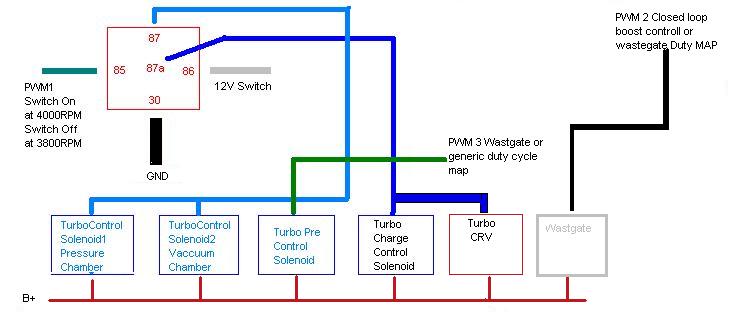
Claudio's method, which is good, was design for use with an E6k IIRC, with an E8 or E11 you have enough outs to control things better.
Whats not shown on this diagram is the turbo pre control and wastgate:
synopsis for them, is too use the wastgate out and wastgate map to control the turbo pre control,
and use the closed loop boost control to control the wastgate itself.
Set the wasgate via the closed loop map to an amount of boost beyond which will be obtainable (you don't want the wasgate opening) prior to the cutover point to the turbo's being NS. Bassicly set it at like 25 PSI or so, and use the pre control to control the turbo's up to the cutover point via the wastgate map.
Just at the cutover point you want the wastgate to start controlling the boost, thats where you set the max PSI.
If you get it just right, the wastgate will be closed as the turbo's cut over to NS causing a slight boost surge that overcomes the dip.
With a 20B, I would move the switch point down, maybe way down to in the neighborhood of 3000-3500.
****, with a 20B pushing one small turbo in seq, I wouldn't be surprised if you could have 15PSI at 1700 RPM, on my car with an REW, I can push 15PSI by 2500 depending on gear.
Last edited by slo; Mar 20, 2008 at 12:32 PM.
Trending Topics
Now that I look at the second method above, my method is functionally similar to it.
But I am connecting the solenoids and vacuum/boost hoses in a simpler way which negates the need for 2 different signals going to the TC (x2) and CRV/CCV.
My method switches them all at the same time rather than having half on and half off for a given state.
Also, you could get away without having a boost chamber but your going to need a vaccum chamber
Last edited by slo; Mar 20, 2008 at 12:45 PM.
Thread Starter
Joined: May 2003
Posts: 4,150
Likes: 0
From: CA (Bay Area)
EVERYONE PLEASE TAKE A BOW! thank you all VERY much! now armed, im headed back to the garage! -Heath
(i have the e11v2 but im trying to conserve as many outputs as i can for other purposes.)
-Heath (i have the e11v2 but im trying to conserve as many outputs as i can for other purposes.)


how much power can a 20B make on stock sequential twins anyway? they are the same HT12's as the FD correct? and a sequential FD typically can do around what, 350rwhp without pushing the turbos too hard...
Thread Starter
Joined: May 2003
Posts: 4,150
Likes: 0
From: CA (Bay Area)
20b - primary ht-15, secondary ht-10 .
the primary is slightly bigger but the secondary is seriously TINY. all 3 rotors feed the primary until transition, after transition the primary is fed by the first 2 rotors, and the 3rd rotor exclusively feeds the secondary. i suppose mazda tried to approximately balance the flow rates between the two rotors on primary, and one rotor on the small secondary.... but considering the options they had to choose from im sure they would have just been happy getting "close enough" .

Thread
Thread Starter
Forum
Replies
Last Post