
Gutting 20b UIM Plenum?


Rotary Enthusiast
Joined: Jun 2004
Posts: 1,457
Likes: 0
From: Gallatin, TN
Originally Posted by sillbeer
My 20b fc had a stock uim and q45 tb on it. No driveability issues when I drove it.
-Destin
-Destin
-Alex


Thread Starter
Joined: May 2001
Posts: 2,390
Likes: 2
From: San Francisco, CA
Thanks for all the informative posts. Keep em' coming!
So my initial thoughts were correct according to you. Thanks for spelling out why I thought it would be like that too. So in turn, I guess it would be safe to assume that lower intake velocities would delay your spool up time when compared to an unmodified plenum, further compounding the problem with low end performance. It also sounds as if one will experience a steeper torque curve too.
I've looked for that thread. All I can find is that he shortened his lim runners and modified the uim to accomodate the 95mm tb. I must have skipped over that info somehow.
Since the car was tuned, as Dragon said it was, and he still experienced bucking at such low throttle postions, wouldn't that indicate too large of an opening permitting too much airflow too soon. This seems to be where the stock tb would be an advantage with it's smaller primary butterfly allowing finer control of airflow to the engine under part throttle.
The stock tb has just slightly more area than an 80mm tb.
The stock tb with big bore seconadaries is closer to the area of a 90mm.
How is that possible without an adapter of some sort. Even if it is unmodified, the large single tb would allow airflow to both the upper and lower divisions of the plenum thereby directing airflow to both primary and secondary runners at all times. In this case, you may as well just gut the plenum since all the chambering in the plenum would only act to inhibit airflow.
Originally Posted by t-von
Depends on how fast your turbo spools! If your turbo is laggy to the point that it isn't going to build boost till the mid rpm ranges, you will notice weaker lower rpm throttle response. Gutting the manifold will lower the intake velocity in the lower rpm's which will in fact slow the amount of air that is drawn into the combustion chambers. The less fuel/air you have drawn in, the less bang you will have and in turn the less torque output you will get. This happens because you will now have air being drawn into the combustion chamber from both primary and secondary ports at the same time all the time. In the really low rpm ranges, a turbo charged engine is just a suction vacuum. So basically your just lowering the engines ability to effectively draw in air efficiently in the lower rpm range. You will however get an increase in the upper ranges due to less restriction the the intake path.
Originally Posted by TT_Rex_7
If you guys would take a moment out and head over to nopistons.com, you'll find a thread posted by Dragon. You'll notice he gutted his UIM, and is running a 90mm TB as well. FWIW, he's having low RPM surging/bucking with such a large TB. IIRC, it's something along the lines of 3-5% throttle at 55mph.
Since the car was tuned, as Dragon said it was, and he still experienced bucking at such low throttle postions, wouldn't that indicate too large of an opening permitting too much airflow too soon. This seems to be where the stock tb would be an advantage with it's smaller primary butterfly allowing finer control of airflow to the engine under part throttle.
Originally Posted by TT_Rex_7
A large TB isn't going to help you a damn bit! The stock TB will flow more than a 90mm TB, and without low RPM issues! A large TB, and gutted UIM is HURTING your performance!! I'm almost willing to bet the volume of the gutted area (plenum) isn't the proper volume. Nor does the gutted area direct airflow properly!
The stock tb with big bore seconadaries is closer to the area of a 90mm.
Originally Posted by sillbeer
My 20b fc had a stock uim and q45 tb on it. No driveability issues when I drove it.
Rotary Enthusiast
Joined: Jun 2004
Posts: 1,457
Likes: 0
From: Gallatin, TN
Originally Posted by RX-Heven
I've looked for that thread. All I can find is that he shortened his lim runners and modified the uim to accomodate the 95mm tb. I must have skipped over that info somehow.
Since the car was tuned, as Dragon said it was, and he still experienced bucking at such low throttle postions, wouldn't that indicate too large of an opening permitting too much airflow too soon. This seems to be where the stock tb would be an advantage with it's smaller primary butterfly allowing finer control of airflow to the engine under part throttle.
Since the car was tuned, as Dragon said it was, and he still experienced bucking at such low throttle postions, wouldn't that indicate too large of an opening permitting too much airflow too soon. This seems to be where the stock tb would be an advantage with it's smaller primary butterfly allowing finer control of airflow to the engine under part throttle.
As for what you said about the stock TB, your 100% correct! If you wanted to really figure things out, you could take the dia. of the primary butter fly valve, figure out how much it opens before the secondary butter fly valves open, and figure out how much it flows. Then take a 90mm TB, and do the same thing. This will tell you the difference right there. I think CCarlisi, and myself already did this, and found quite a large difference between the two! It's just been a while, and I can't remember the exact numbers!

Edit: Just thought of this...The stock primary butter fly valve is 45mm, which is half of a 90mm TB. So, the 90mm butter fly valve will flow twice the amount of air at low RPM's when only the primary butter fly valve is open!
Does anyone know what RPM/throttle position you would be at at 55mph in 4th or 5th gear? You figure if Dragon is at 3%, and if the primary butter fly valve is the only one open, then it would take 6% throttle with the stock TB.
I also remember Dragon having issues with the car taking off when barley hitting the gas pedal...The cause of this would all be because of above. If you think about it, since a 90mm is twice the size of the primary 45mm TB, then whenever the primary butter fly valve is the only one open, it'll take half the pedal effort as well!
I would say due to all the reasons above, STAY AWAY FROM A 90MM TB!!

Originally Posted by RX-Heven
The stock tb has just slightly more area than an 80mm tb.
The stock tb with big bore seconadaries is closer to the area of a 90mm.
The stock tb with big bore seconadaries is closer to the area of a 90mm.
Originally Posted by RX-Heven
How is that possible without an adapter of some sort. Even if it is unmodified, the large single tb would allow airflow to both the upper and lower divisions of the plenum thereby directing airflow to both primary and secondary runners at all times. In this case, you may as well just gut the plenum since all the chambering in the plenum would only act to inhibit airflow.
-Alex
Edit: I would be curious to hear GtoRx7's experience with his ITB's!
BTW, who would be interested in a casted UIM!
Last edited by TT_Rex_7; Aug 7, 2006 at 03:20 PM.
Thread Starter
Joined: May 2001
Posts: 2,390
Likes: 2
From: San Francisco, CA
Originally Posted by TT_Rex_7
I got the info from CCarlis, so you may want to send him a PM to find the exact thread. I was also told it was a 90mm, not a 95mm. However, I really don't think it would make much of a difference...
btw, It was a 95mm tb he used.
Originally Posted by TT_Rex_7
Edit: Just thought of this...The stock primary butter fly valve is 45mm, which is half of a 90mm TB. So, the 90mm butter fly valve will flow twice the amount of air at low RPM's when only the primary butter fly valve is open!
For refence:
Area 90mm circle = 6362mm squared
Area 80mm circle = 5026mm squared
Area 45mm circle = 1590mm squared
Originally Posted by TT_Rex_7
I also remember Dragon having issues with the car taking off when barley hitting the gas pedal...The cause of this would all be because of above. If you think about it, since a 90mm is twice the size of the primary 45mm TB, then whenever the primary butter fly valve is the only one open, it'll take half the pedal effort as well!
Originally Posted by TT_Rex_7
How are you coming to this conclusion?
Find the area of each opening in the stock tb and add the three of them together.
Diameter of primary = 45mm
Diameter of seconadry = 50mm
So:
Primary = 1590mm squared
Secondary = 1963.5mm squared
Then:
Primary + (2)Secondary = 5517 mm squared
Originally Posted by TT_Rex_7
BTW, who would be interested in a casted UIM!
I would be.
Did I mention I'd be interested?
Yes I would be be interested.
Something along the line of the Ground Zero cast lower manifold and an upper manifold, but for a 20b would be awsome. The demand for it would be small but there would definately be a market for a setup like that.
Yeah, I'd buy one.
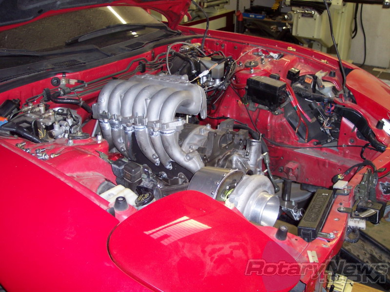
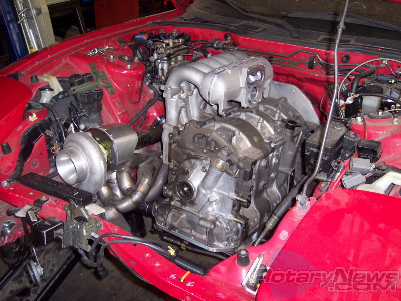
Also, I came across these pics of a 20b fd conversion that Abel Ibarra is doing. Looks like he gutted the plenum and is using the stock (or fd) tb with it.
I don't really have any info on it though.
Last edited by RX-Heven; Aug 7, 2006 at 07:16 PM.
Rotary Enthusiast
Joined: Jun 2004
Posts: 1,457
Likes: 0
From: Gallatin, TN
Originally Posted by RX-Heven
I honestly believe Dragon did not gut the interior of his manifold. He only welded on a flange to adapt the 95mm tb and chopped the lim to reduce the overall height of the intake system.
btw, It was a 95mm tb he used.
btw, It was a 95mm tb he used.
Originally Posted by RX-Heven
Actually, a 90mm opening would flow 4 times the air a 45mm opening would. The area of circles is not a 1:1 ratio.
For refence:
Area 90mm circle = 6362mm squared
Area 80mm circle = 5026mm squared
Area 45mm circle = 1590mm squared
It will take 1/4 the effort...making it even harder to accelerate slow and smooth.
Area of a circle = (pi) x (radius) x (radius)
Find the area of each opening in the stock tb and add the three of them together.
Diameter of primary = 45mm
Diameter of seconadry = 50mm
So:
Primary = 1590mm squared
Secondary = 1963.5mm squared
Then:
Primary + (2)Secondary = 5517 mm squared
2 + 2 =....what again?! 
At any rate, I think this clearly shows that a 90mm is the wrong option for most of us! I plan on doing the math to a 70, 75, and 80mm TB to see how it comes out. Chris, Guru Motorsports, Auto Illusions, and myself have been figuring between a 70mm-80mm TB.
Originally Posted by RX-Heven
ME!
I would be.
Did I mention I'd be interested?
Yes I would be be interested.
Something along the line of the Ground Zero cast lower manifold and an upper manifold, but for a 20b would be awsome. The demand for it would be small but there would definately be a market for a setup like that.
Yeah, I'd buy one.
Nice thing is the UIM would have a proper plenum, and would direct air evenly. A LIM would be nice if made shorter than the factory one for hood clearance, and again, even out the air flow. Not that I have a 20B anyways...But it'd sure help you guys out alot!
Originally Posted by RX-Heven
Also, I came across these pics of a 20b fd conversion that Abel Ibarra is doing. Looks like he gutted the plenum and is using the stock (or fd) tb with it.
I don't really have any info on it though.
I don't really have any info on it though.
-Alex
Last edited by TT_Rex_7; Aug 7, 2006 at 09:20 PM.
Rotary Enthusiast
Joined: Jun 2004
Posts: 1,457
Likes: 0
From: Gallatin, TN
Originally Posted by big_rizzlah
i would be interested if there were some sort of data (ie- dyno sheets) telling me that it was a good idea. definitely interested
I'm sure just about anything would be an improvement over the stock UIM though!
-Alex

Senior Member
Joined: Nov 2004
Posts: 627
Likes: 0
From: Fallston, MD
Guys, I have to disagree. I know a rotary engine isn't a piston engine and all, but I have to think that driveability issues with a 90mm TB is a tuning issue. There are people running 100mm TBs on Supras, and they don't flow the kind of air that the 20B does. If the Supra guys can figure it out, surely the rotary guys can.
Rotary Enthusiast
Joined: Jun 2004
Posts: 1,457
Likes: 0
From: Gallatin, TN
Originally Posted by rarson
Guys, I have to disagree. I know a rotary engine isn't a piston engine and all, but I have to think that driveability issues with a 90mm TB is a tuning issue. There are people running 100mm TBs on Supras, and they don't flow the kind of air that the 20B does. If the Supra guys can figure it out, surely the rotary guys can.
The simple facts of this matter are posted above. The stock TB is setup to allow only the primary butter fly valve to open for a reason...When adding a 90mm TB on a rotary, your allowing 4 times the amount of air (Thanks to Rx-Heven for clearing this up!
) in at partial throttle, when only the primary butter fly valve is opened on the stock TB. When only a 1/4 of throttle needs to be applied compared to stock, it creates serious low RPM driving issues.Think of it like this...Lets say to maintain 25MPH, you have to apply 1/4 amount of pedal travel...Well, with a standard 90mm TB, you'd only have to apply 1/16 worth of pedal travel! This probably plays a roll in the "bucking" issue as well. Your not used to applying such small amounts of throttle, and you start allowing to much air in by pushing in the gas pedal to much. I doubt this would be something easy to get used to either.
No tuning in the world will fix the pedal travel issue. The only possible way to fix that would be with a drive-by-wire setup, which CCarlisi and I were discussing earlier.
-Alex
Last edited by TT_Rex_7; Aug 8, 2006 at 12:22 AM.

Originally Posted by TT_Rex_7
However, your belief of keeping the primarys separate from the secondarys is incorrect. -Alex
I meant that in terms of having better low rpm driveability at partial throttle. They do need to be separate in the sense that air flow isn't flowing through both runners at the same time at such a low rpm. That's what I meant.
Originally Posted by TT_Rex_7
Besides all of that, the TB isn't what's hurting the performance. It's simply the design of the UIM. (As well as the LIM) If you don't have the money to purchase a new TB, or an ITB setup, do what t-von suggested, make a custom UIM, and keep the runners seperate, and use the stock TB.
-Alex
I can't wait to show you guys what I'm currently trying to engineer.
Thread Starter
Joined: May 2001
Posts: 2,390
Likes: 2
From: San Francisco, CA
Originally Posted by TT_Rex_7
Well, you certainly took some time out to apply some math. I just took the easy way out and assumed half! 2 + 2 =....what again?!
2 + 2 =....what again?!
Originally Posted by TT_Rex_7
At any rate, I think this clearly shows that a 90mm is the wrong option for most of us! I plan on doing the math to a 70, 75, and 80mm TB to see how it comes out. Chris, Guru Motorsports, Auto Illusions, and myself have been figuring between a 70mm-80mm TB.
For drag racing, a giant single plate butterfly would be fine as you don't care about part throttle.
For road racing, as with what I'll be doing, throttle modulation and the ability to control it is very crucial. However, you still want that big top end that more cfm will provide. This is why I will be sticking with the fd tb. The secondary butterflies will be opened up and will flow as much as a 90mm tb and I'll still have that nice little primary to help with part throttle applications.
With a street car, all that matters is what you are willing to sacrifice, power at the expense of convienence and/or comfort. Whatever that is means different things to different people.
Having talked to Brian at Rotorsports, he claimed his 20b with the stock lim/uim and tb made 470 rwhp @10lbs (with a GReddy T-78 or T-88). After extrude honing both manifolds and opening up the secondaries in the fd tb he claimed 527 rwhp @ 10lbs with all else being equal.
Originally Posted by TT_Rex_7
Chris and myself have been talking about this for quite some time! Currently I'm busy doing alot of things, but may be something I'd do in the future. However, I'd really like 10 people to get the ball rolling. Not sure how easy/hard that'd be though!
Nice thing is the UIM would have a proper plenum, and would direct air evenly. A LIM would be nice if made shorter than the factory one for hood clearance, and again, even out the air flow. Not that I have a 20B anyways...But it'd sure help you guys out alot!
Nice thing is the UIM would have a proper plenum, and would direct air evenly. A LIM would be nice if made shorter than the factory one for hood clearance, and again, even out the air flow. Not that I have a 20B anyways...But it'd sure help you guys out alot!
Originally Posted by rarson
Guys, I have to disagree. I know a rotary engine isn't a piston engine and all, but I have to think that driveability issues with a 90mm TB is a tuning issue. There are people running 100mm TBs on Supras, and they don't flow the kind of air that the 20B does. If the Supra guys can figure it out, surely the rotary guys can.
As stated before by Alex, no amount of tuning will change the fact that at any given position at part throttle (when compared to the stock tb's primary only), you will flow 4 times the amount of air with a single 90mm tb.
Many cars now come with tb's like that and a few I've driven have had crappy part throttle response imho.
Originally Posted by power hungry
By the way acosta runs a 100mm accufab TB on his rx8.
4" = 100mm
I remeber asking him about that at Sevenstock a few years ago when he brought that car out. He said the throttle was very sensitive.
Remeber, he's a drag racer too.
Originally Posted by t-von
I can't wait to show you guys what I'm currently trying to engineer.
I finally decided on what I'm going to do
Rotary Enthusiast
Joined: Jun 2004
Posts: 1,457
Likes: 0
From: Gallatin, TN
Originally Posted by RX-Heven
I'd think anything that flows less than the stock tb would be bad. Remeber, the stock tb flows a hair more than an 80mm tb. An increase would definateley open things up for the 20b but it is in how you do it and what you plan on doing with the car.
So now there's two issues that come into play larger intercooler piping to accommodate a larger TB...
1. Room! Does everyone have the room to go with larger intercooler piping? going from 3" piping to 3.5" piping eats up quite a bit of room.
2. What's the size of your compressor outlet? If it's 2.5", or even 3", what good will 3.5" intercooler piping do? Only thing I see it doing is taking up more room, and increasing responce time!
In other words, before everyone goes off and starts slapping on larger TB's, you need to look at the rest of your setup. Your not going to make any more power with a 3.5" TB, when you only have 3" intercooler piping...
Originally Posted by RX-Heven
For drag racing, a giant single plate butterfly would be fine as you don't care about part throttle.
Originally Posted by RX-Heven
For road racing, as with what I'll be doing, throttle modulation and the ability to control it is very crucial. However, you still want that big top end that more cfm will provide. This is why I will be sticking with the fd tb. The secondary butterflies will be opened up and will flow as much as a 90mm tb and I'll still have that nice little primary to help with part throttle applications.
I see no reason why you can't slightly enlarge the primary butter fly valve though. I'm pretty sure a few MM's won't hurt partial throttle situations.
Originally Posted by RX-Heven
Having talked to Brian at Rotorsports, he claimed his 20b with the stock lim/uim and tb made 470 rwhp @10lbs (with a GReddy T-78 or T-88). After extrude honing both manifolds and opening up the secondaries in the fd tb he claimed 527 rwhp @ 10lbs with all else being equal.
Regardless, if it IS true, just image what a new LIM and UIM would do!! The extrude hone process, nor the larger TB did anything for better flowing characteristics (It just simply allowed for more airflow) so there's still quite a bit to be "unlocked" here with a new LIM and UIM!!
Originally Posted by RX-Heven
Personally I think the lim would be the better candidate. I would not complain if both were available though.
-Alex
Last edited by TT_Rex_7; Aug 8, 2006 at 07:50 PM.
Senior Member
Joined: Nov 2004
Posts: 627
Likes: 0
From: Fallston, MD
Well I was more thinking out loud. And by "tuning" I didn't mean just ECU tuning but tweaking the entire setup in general. I certainly think adjusting the throttle cable to a proper position would be required at the very least.
In fact, I was thinking about something: you know the "cam" that the throttle cable actuates? What if we designed that cam not to be circular but to have a sort of slope to it, so that the amount of change of throttle position versus cable movement would get progressively larger the more the pedal was pressed? More thinking out loud, I guess.
In fact, I was thinking about something: you know the "cam" that the throttle cable actuates? What if we designed that cam not to be circular but to have a sort of slope to it, so that the amount of change of throttle position versus cable movement would get progressively larger the more the pedal was pressed? More thinking out loud, I guess.
Rotary Enthusiast
Joined: Jun 2004
Posts: 1,457
Likes: 0
From: Gallatin, TN
Originally Posted by rarson
In fact, I was thinking about something: you know the "cam" that the throttle cable actuates? What if we designed that cam not to be circular but to have a sort of slope to it, so that the amount of change of throttle position versus cable movement would get progressively larger the more the pedal was pressed? More thinking out loud, I guess.
There's easy enough ways around this problem, so I'd say just use them, rather than try and make things more complicated! Really just up to the individual though...
BTW, does anyone have a picture of one of these "cams?"
-Alex
'Tuna'
Joined: Feb 2001
Posts: 4,637
Likes: 3
From: Miami,Fl,USA
Originally Posted by TT_Rex_7
Me and CCarlisi talked a while about a different cam as well. I think we ended up coming to the conclusion that unless one is readily available that will work for our application, it's just more work and cost. I wouldn't want to be the one to figure out the design of the cam!
There's easy enough ways around this problem, so I'd say just use them, rather than try and make things more complicated! Really just up to the individual though...
BTW, does anyone have a picture of one of these "cams?"
-Alex
There's easy enough ways around this problem, so I'd say just use them, rather than try and make things more complicated! Really just up to the individual though...
BTW, does anyone have a picture of one of these "cams?"
-Alex
As for driveability with huge throttlebodies it's mostly a tuning issue. I have 13b's with 90 and 95 mm and done supras with 105mm with no tuning or driveability issues.
Rotary Enthusiast
Joined: Jun 2004
Posts: 1,457
Likes: 0
From: Gallatin, TN
Originally Posted by crispeed
I have 13b's with 90 and 95 mm....
If stock, what'd you do for a plenum?
I'm trying to get specifics to see how it compares to the issues people are running into with the 20B. I already said from the start, along with others in this thread, that how the air enters the gutted UIM is an issue.
Another reason why you may not be running into issues is due to the design of the FD UIM. As we all know, it has a much better design. I would assume you made some sort of custom plenum, therefore it would solve the air distribution problem above. If you simply made an adapter plate, and bolted it on, the restrictions involved may be the reason your not seeing any "bucking" issues at low RPMs. However, I doubt this is the case since I've seen your work!
A stock/custom LIM plays a roll here as it involves distributing the air properly as well!
Without a diffrent cam, or a drive-by-wire system, I still don't see how you got away without any pedal modulation issues. I know you said the Q-45 TB has a different type of cam, but it doesn't explain the 95mm TB...
As usual, there always seems to be more questions than answers!
-Alex
Edit: It'd be nice to get some more tuners in here to discuss how much of a role tuning may be playing here...Someone get Sean (A-spec) and Steve (Gotham Racing) in here!
Last edited by TT_Rex_7; Aug 9, 2006 at 03:36 AM.
Originally Posted by TT_Rex_7
Edit: It'd be nice to get some more tuners in here to discuss how much of a role tuning may be playing here...Someone get Sean (A-spec) and Steve (Gotham Racing) in here!
We also need info from guys guys like Rotarygod and Paul Yaw who really understand the true dynamics of intake design.
Senior Member
Joined: Nov 2004
Posts: 627
Likes: 0
From: Fallston, MD
Originally Posted by crispeed
The huge Q-45 throttle body that everyone runs has the cam design into it from factory. You should look into that if you want some ideas.
As for driveability with huge throttlebodies it's mostly a tuning issue. I have 13b's with 90 and 95 mm and done supras with 105mm with no tuning or driveability issues.
As for driveability with huge throttlebodies it's mostly a tuning issue. I have 13b's with 90 and 95 mm and done supras with 105mm with no tuning or driveability issues.
So, the question is, what can be done with the tuning to help the driveability issues?
Having gutted a couple of intake manifolds over the years I can say that it absolutely does make a difference. I've done it 2 ways on my old 2nd gen. I have used a single 75mm Mustang throttlebody and have used just the stock tb with a gutted plenum chamber. Both behaved very closely to the other one which was not like stock. The throttle is more touchy. I even tried a 75 mm on an n/a which I can say while technically drivable is not anything that had any point to it.
Boost does appear to come on faster but that's because of the obvious reason that the engine is getting more air for the same throttle level. Even with the gutted plenum and the stock tb. There does come a certain point in size where full throttle is no different airflow wise to the engine than a lower throttle setting. The engine can only flow so much air. I used to have a turbo 2nd gen that did a little over 400 rwhp. Plenty for me but not as much as many here would like. With the 75mm tb, it worked fine but if I could go do it again, I'd use a 70 mm unit. When the outlet of the turbo is noticably smaller than the throttleplate, there isn't a whole lot of point to going much larger.
The thing about the stock plenum chamber (dynamic chamber) that people don't always realize is that being divided really affects the total amount of air getting to the engine. Remember that all of the air in the primary ports must flow through only 1 throttle plate and in the case of the 3rd gens and 20B's, this meant through a smaller throttleplate than the other 2. The air in the secondaries received all of their air from 2 larger throttle plates. There is a flow imbalance.
Even though we have 2 intake runners per rotor, air does not necessarily try to flow through the other if one of them backs up. It is because of a pressure balance that happens between each runner. You will not have more pressure in one runner than the other. It will equalize. The problem is when you max out the flow capabilities of the primary plate. When this happens, the pressure is still equal between it and the secondaries. If one runner had less pressure in it than the other, the air would travel from one runner and towards the other causing the air to go backup into it. That doesn't happen. The end outcome is that pressure backs up which causes heat in the air and a loss in power. You start needing to work harder to get every little bit more in power. You really don't end up using all of the extra capacity of the secondary runners. Logic would say you do but do to a pressure balance, you don't.
By hogging out the plenum into one large chamber, you have remedied this. Now the engine has equal distribution through all of the throttle plates. Every runner shares air from every plate. This is the same thing that happens on a piston engine with a dual plane manifold vs a single plane. The average airspeed through the throttlebody actually decreases. That actually sounds weird to many people so you'll have to go study up on piston engine manifold design to see why. Hogging out the plenum is has the same effect as using a larger throttlebody. It is for this reason that I said if I could go back and build my old 2nd gen again, I'd use a smaller throttlebody.
You can not make a direct comparison of the total area of the multiple throttlebody plates without first comparing what type of intake manifold the multi plate tb is on. In a single plane manifold, you can make the comparison. Understand that even with the same total area, the single plate tb will flow a bit more. There is less in the way. Just look at it. A flow bench will verify this. Don't be too concerned about the small difference though.
A nice side effect of hogging out the plenum is that you increase flow through the runners. This is even more true with a single plate throttlebody. The air actually turns less sharply now. Turns are bad for flow, especially sharp ones. Again, if you don't understand why this is, either go build a mockup out of cardboard and just look at the flow path or go find some websites explaining intake theory with pictures. Some things aren't obvious and other times you'll find common sense doesn't mean a thing. Air is funny stuff.
just to add a couple things to the confusion:
1) 2 runners will flow significantly less than a single runner with an equal x-sectional area, because drag in a pipe is based on the ratio of x-sectional area to wall surface area. think about it this way...when a fluid (air) flows past any surface, there is a gradient of fluid velocity, beginning at 0 right at the wall, and then ending at the maximum velocity in the center of the pipe. simple speaking, the air that touches or is very near to the wall of the pipe flows much slower, so that flow increases disproportionately to diameter.
2) keep in mind that the center rotor on a 20b is what blows in about 70% of them. this is because even with the stock manifold and all its dividers and stuff, the airflow is still directed right into the center ports. if you hack all that junk out of there, you might get a better total flow, but you will make the center rotor even leaner than it was before.
3) what someone said about needing to consider the size of everything else in the system and make it all the same is only partly true. for example, if you have a 2.5" compressor outlet, it is NOT true that 3" IC piping is a waste of space. a bottleneck in a system is not good, but its a lot less restirictive than having the whole system that size. its a good point that if you have 4 feet of 2" IC piping than changing from a 4" to a 5" TB isnt going to make much difference, but barring extreme examples like that, in general bigger is almost always better, regardless of unreplaceable bottlenecks.
IMO, as far as the stock manifold goes, its basically just love it or leave it. yes, the dividers and the small TB are restrictive. but cutting around on it is somewhat counter productive due to the center rotor problem and also due to the fact that most of us arent perfect fabricators, and small imperfections and inorganic shapes can hurt flow quite a bit. the best way to go is really just to make a completely custom manifold. that way you can use slightly smaller runners for the center rotor, and design the whole thing with smooth curves, a lower profile, and bigger openings in general. A manifold like this is what I will be making when I shoot for big power numbers. (also when i am less broke, and can afford more ramen noodles)
pat
Last edited by patman; Aug 23, 2006 at 11:32 PM.