
Tfidfis


TFIDFIS works great, however I don't recommend using it with stock 50a alternator, but I'm using trailing still and eliminating that might help, plus, it's also cold here and the heater is on full blast always...

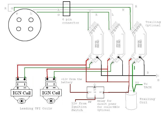
I just did this setup on my 85 SE that I haven't been able to get to run over the past year. For some reason it fired up after doing this, but I'm getting no spark out of my leading coils. I had the HEI modules tested and they tested good, both coils are measuring the same. The aluminum plate the modules are on is getting hot, but I'm just not getting any spark. I'm baffled why its running off the trailing now and it wouldn't start before. I used the following diagrams to wire everything up with.

Thread Starter
Joined: Jul 2004
Posts: 9,266
Likes: 467
From: Lake Wylie, N.C.
Re-examine all your wiring. Might just be a simple mistake. Also make sure you have the grounds
on the HEIs correctly or they will not function very well. The grounds go to the screw hole with a metal
collar on it.
BTW, those 2 drawings are for different HEI modules. The top one is for the 7 pin HEI (newer) and
the bottom is for the 4 pin. So which HEI are you actually using. Notice the P,N connections on
7 pin are opposite the ones for the G,W connections on the 4 pin. Depending on which HEI you
used and which diagram you looked at it could be backwards.
I hadnt noticed they were for 2 different modules but i did go off the correct drawing for the 7 pins i have.
I did get the leading firing but the timing is off on it. When I hooked up a timing light, the car was idling around 800-1k rpms, but the timing light was reading over 5k, is this normal for this setup or is something still not right with it?
I did get the leading firing but the timing is off on it. When I hooked up a timing light, the car was idling around 800-1k rpms, but the timing light was reading over 5k, is this normal for this setup or is something still not right with it?
Thread Starter
Joined: Jul 2004
Posts: 9,266
Likes: 467
From: Lake Wylie, N.C.
Are you talking about a timing light or a tach? 5k? The timing should be base on the pully marks and
typical leading timing at 4K and above should be advanced to around 24 degrees +- a few degrees
depending on what your engine likes.
typical leading timing at 4K and above should be advanced to around 24 degrees +- a few degrees
depending on what your engine likes.
The tech reads 800-1k rpms, the timing light reads 5k. I would think the timing light would read incorrect on a rotary in the first place since the same plug fires 3 times for every rotation, add that both plugs are firing at the same time, that puts it firing 6 times per a standard rotation, which would explain why the timing light is reading much higher than what the tach reads...at least that is what I have worked in my head.
As for its timing: when i saw the timing mark on the pulley at idle it was wayyy advanced, more than you can fix from adjusting the distributor. I removed the distributor, followed the instructions in my manual to set it tdc and now it currently doesnt run. I do not know if someone removed the pulley for any reason and didnt install it correctly. So now i have another weekend project.
As for its timing: when i saw the timing mark on the pulley at idle it was wayyy advanced, more than you can fix from adjusting the distributor. I removed the distributor, followed the instructions in my manual to set it tdc and now it currently doesnt run. I do not know if someone removed the pulley for any reason and didnt install it correctly. So now i have another weekend project.
Thread Starter
Joined: Jul 2004
Posts: 9,266
Likes: 467
From: Lake Wylie, N.C.
I guess I'm too old school, my timing light just flashes on and off. It doesn't tell me the rpm
based on the frequency of the signal. I suppose there is a setting for it to know if your on a 4,
6 or 8 cylinder. You can play with that I guess.
Yeah, your pulley could be out of whack. The good news is it was running and sounds like it
was close to right. Hope you get it figured out. Let us know.
Yea I think my issue is the timing light I have is too fancy for it. I just borrowed it off a guy at work.
I did finally get her running correctly, still haven't had any luck with the timing light. But I went through, found TDC, reset the crank pulley, reset the distributor and for some reason it was idling rough and was back firing above 2k. Tried moving the distributor a tooth either direction and nothing. On a wild guess I decided to switch the pickup wires to the leading ignition modules....and Viola!
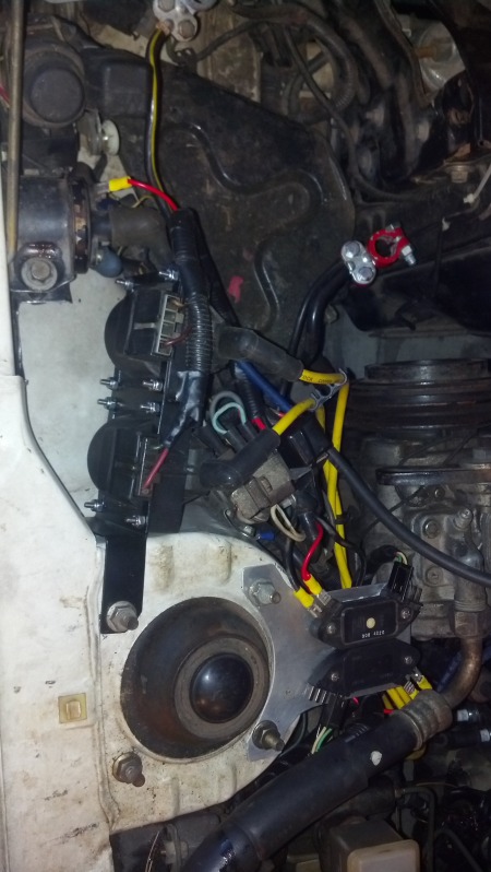
Thanks for the write up guys. I will get pics of the setup after I get her back on the road.
I did finally get her running correctly, still haven't had any luck with the timing light. But I went through, found TDC, reset the crank pulley, reset the distributor and for some reason it was idling rough and was back firing above 2k. Tried moving the distributor a tooth either direction and nothing. On a wild guess I decided to switch the pickup wires to the leading ignition modules....and Viola!
Thanks for the write up guys. I will get pics of the setup after I get her back on the road.
I am going to bump this extremely useful older thread...
How much does the actual coil choice affect the outcome of this setup? By this I mean, using a Mustang MSD coil versus the stock Ford TFI coil? Or using a traditional style cylinder type blaster 2 coil?
I plan to run this on my Rx2 with an 85 distributor and 12a. I do not plan on running the trailing at all. So using the most up-to-date drawing posted above using 4 pin igniters, do I just pretend as if the wiring going to and from the trailing coil and ignitor do not exist?
Also, since I will not be using the trailing or running any plug wires from the distributor all together, I suppose there is a way to use the 2nd CAS?
And what about using "smart" coils? These are coils with built in igniters like the D585 (Yukon coils). If we could use these, then a lot of the mess and hassle with the HEI igniters would go away.
And what about using "smart" coils? These are coils with built in igniters like the D585 (Yukon coils). If we could use these, then a lot of the mess and hassle with the HEI igniters would go away.
Thread Starter
Joined: Jul 2004
Posts: 9,266
Likes: 467
From: Lake Wylie, N.C.
Back from the weekend! You can't use the CAS as you would need an
advancing mechanism or the treat it likea locked dizzy. Also the signal
from the CAS would need to be converted into a waveform that would
drive the ignitors. You really need a standalone to use a CAS.
Any good coils will work fine. I like the E or TFI coils because
they are solid state, no oil to leak or go bad and they are
fairly heat tolerant.
No clue on the Yukon coil but, hey, give it a try and post
pack.
Full Member
Joined: Apr 2014
Posts: 138
Likes: 1
From: Wheeling WV
I'm gathering parts for my own conversion here soon, has anyone thought/committed to installing LED's on the input side of the HEI as a built-in diagnostic light? or would this cause too much signal loss? 32v 20mA red led's, no fancy stuff, just old school flush mounted resistor-included status lamps. I do however plan to install a spare tach under-hood for carb and ignition tuning purposes.
Finally got everything sorted out and did my split timing 24L 16T, and my car is running like a champ.
Funny thing is, I go through all this trouble of measuring and marking my pulley.

free picture upload
I show up to my friends shop to do the timing and he brings out this. LOL

free image host
Funny thing is, I go through all this trouble of measuring and marking my pulley.
free picture upload
I show up to my friends shop to do the timing and he brings out this. LOL
free image host
You shouldn't use masking tape and you shouldn't use inches. Masking tape will stretch ruining your measurements and the pulley is metric 360mm circumference. 1mm = 1 degree. Mazda was pretty smart when they designed this. Makes it dead simple for us.
Oh and you're not really supposed to use a timing light with a dial like that. j9fd3s can explain why better than I could.
Oh and you're not really supposed to use a timing light with a dial like that. j9fd3s can explain why better than I could.
I just went by this turorial
timing
You will need a pair of vernier calipers, a small file or hack saw blade, a roll of masking tape
Now multiply .196 by two (.393). Set your calipers to this number, and make another mark .393 inches
Thread Starter
Joined: Jul 2004
Posts: 9,266
Likes: 467
From: Lake Wylie, N.C.
It does make a difference but lucky for you the second diagram is right. Mine has a typo with the
relay pinouts mislabeled. Surprised no one else caught this until now.
Anyway, I'll post a revision up when I get a chance.
relay pinouts mislabeled. Surprised no one else caught this until now.
Anyway, I'll post a revision up when I get a chance.
Full Member
Joined: Apr 2014
Posts: 138
Likes: 1
From: Wheeling WV
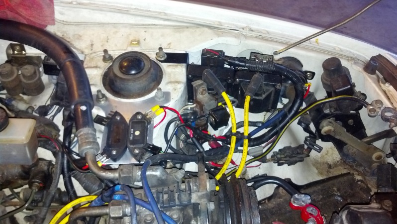
i'll play. got this all mounted down, had a dead HEI ignitor @ high rpm and two broken coil outputs from the TFI's. I officially hate borg warner electrical parts. PTUI! took it off and went stock. will probably revisit the whole idea but not do the trailing ones. maybe after bridgeporting the spare engine and swapping it in.
I changed the leads on the relatively new NGK wires to accept the TFI "outies"
I plugged into the dizzy with soldered mini ATO fuse blades onto the wiring going to the GM ignitors. everything fused and ran from relay. (epiphany hit yesterday - I have no direct wire from alt to b+ on this damned car!) so no wonder it didnt feed even 13v to it all, my stock spec setup is gonna be great soon.
Thread Starter
Joined: Jul 2004
Posts: 9,266
Likes: 467
From: Lake Wylie, N.C.
Sorry it didn't work out this time but thats some nice looking work you put into it so far.
Sometimes you have to walk away from a project and let it sit to get it right.
Sometimes you have to walk away from a project and let it sit to get it right.

Senior Member
Joined: Oct 2008
Posts: 380
Likes: 3
From: palmetto
It seems to work very well. My chokeless Nikki starts quickly and settles to idle in less than a minute. Once warm, even with AC on, it starts with a flick of the key and no throttle. It wouldn't do that with the stock setup.