
REW with first gen front cover timing and TII CAS install

REW with first gen front cover timing and TII CAS install
Hi guys,
Please help me figure out how to stab the TII CAS in correctly on my REW with 12a front cover. I'll be using the REW main pulley since I'm keeping the REW waterpump and alternator.
My research so far tells me the REW's stock timing mark on the trigger wheel is -20*. But that's based on the REW's front cover pointer which is located more counter clockwise than the 12a. The pulley can also only be installed one way. I also found all first and second gen front covers have the pointer in the same position.
I've rotated my assembly so that the auto counterweight is in between the 2 bolts seen through the top inspection plate so it's "close" to TDC. Does anyone know how many degrees difference there is between the -20* mark of the REW trigger wheel and 0* of a 12a pulley/pointer on the front cover. I believe that's what I would need to mark my pulley correctly but if you guys have any other ideas, please let me know. Or let me know if I'm going about it the wrong way. I want to make sure I will be stabbing the TII CAS correctly. TIA.
ok, i think i figured out how to best find TDC. the key on the flywheel/counterweight should be at 9 o'clock when looking at the engine from the rear. this corresponds to the left most and right most holes that bolt the flywheel to the counterweight and the clutch plate to the flywheel. so...put a straight edge on the 2 bolt holes and make sure it is parallel to the oil pan mating surface. i just used a level to make sure they were equal.
here's a great pic Siraniko had provided. imagine a horizontal line connecting the left and right most holes.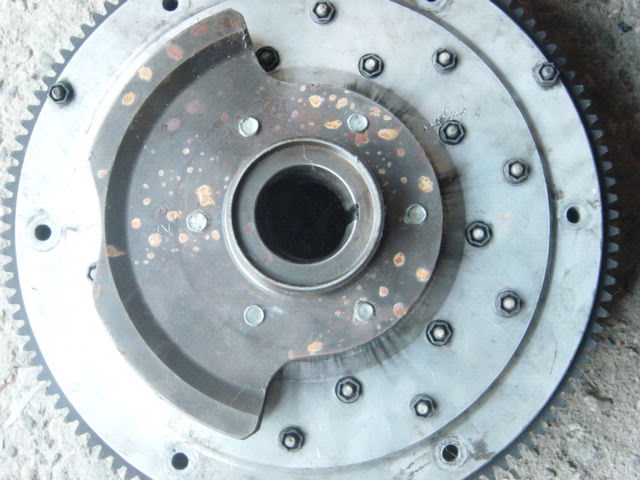
here's a great pic Siraniko had provided. imagine a horizontal line connecting the left and right most holes.

Thread
Thread Starter
Forum
Replies
Last Post