
My 2GCDFIS w/TT & Ignitor cooler

My 2GCDFIS w/TT & Ignitor cooler
I got the 2GCDFIS w/TT setup in the mail a couple days ago and tackled the project right away. I mounted the 2g coil on the strut tower since that seemed the most convenient of places and it seems like that is what everybody is doing. Went ahead and connected all the wires and gave it a shot.
She fired right up with no problems at all and ran fine. I let it idle for
a good 10 minutes and poked around at the wiring and coil and noticed that the coil was almost too hot to touch. So I posted my dilema here on the forum and sure enough, it is a common problem (didn't read that far into the writeup).
I was going to attach a computer heat sync to the coil mounting plate but gsl-se addict suggested a CPU fan.....which sounded like it would work much better.
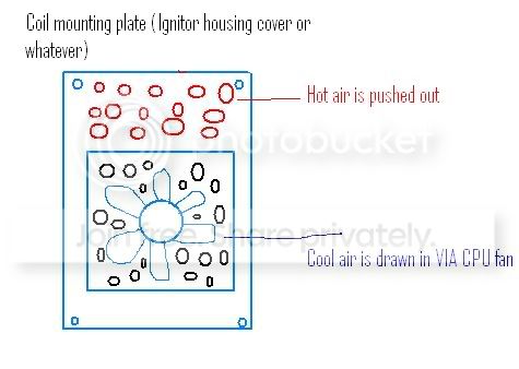
I drilled a bunch of holes near the bottom of the plate in a manner so that when the fan pushes air into the ignitor housing, the hot air will escape out the top of the plate. See crappy drawing below:
I then attached the fan with a ziptie (use your imagination), wired it up to the same (+) and (-) I hooked the transistor to and it was done. I fired it up and let it idle for 10-15 minutes and it stayed almost as cool as it did with the engine not running.
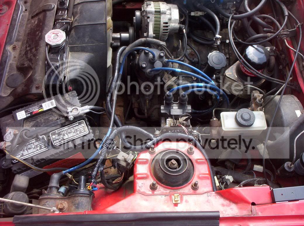
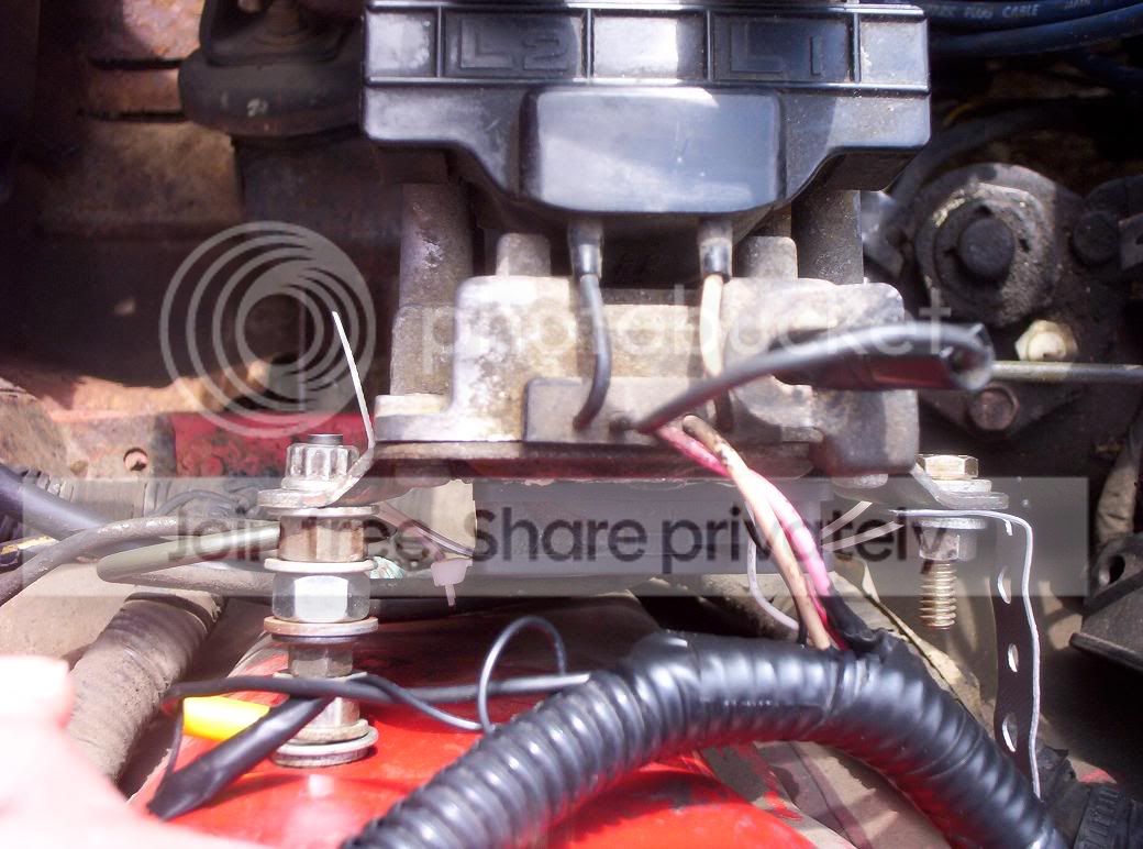
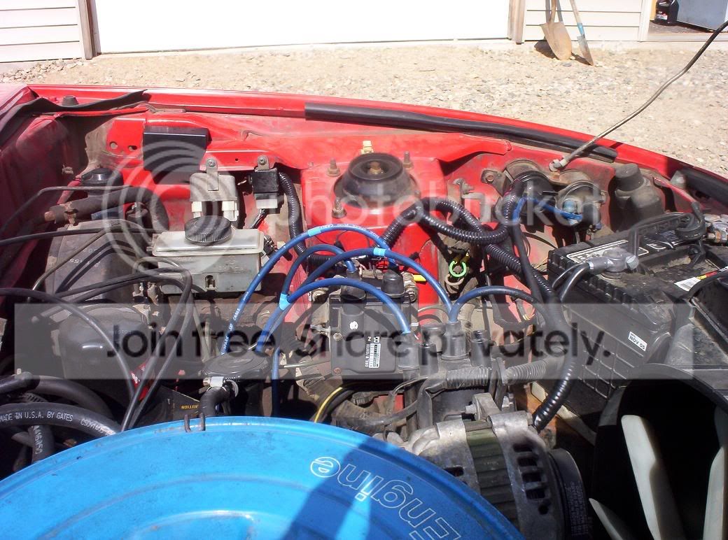
Here are some pictures of the setup and I know it looks rigged (mounting bolts and sutch) but it is quite solid! I used an upper intake stud from my old 89 turbo Ranger to fasten the left side of the coil since it had 2 different thread sizes and worked out great (it even had a stationary hex nut in the middle so I could secure it to the strut tower with ease).
Justin
She fired right up with no problems at all and ran fine. I let it idle for
a good 10 minutes and poked around at the wiring and coil and noticed that the coil was almost too hot to touch. So I posted my dilema here on the forum and sure enough, it is a common problem (didn't read that far into the writeup).
I was going to attach a computer heat sync to the coil mounting plate but gsl-se addict suggested a CPU fan.....which sounded like it would work much better.
I drilled a bunch of holes near the bottom of the plate in a manner so that when the fan pushes air into the ignitor housing, the hot air will escape out the top of the plate. See crappy drawing below:
I then attached the fan with a ziptie (use your imagination), wired it up to the same (+) and (-) I hooked the transistor to and it was done. I fired it up and let it idle for 10-15 minutes and it stayed almost as cool as it did with the engine not running.
Here are some pictures of the setup and I know it looks rigged (mounting bolts and sutch) but it is quite solid! I used an upper intake stud from my old 89 turbo Ranger to fasten the left side of the coil since it had 2 different thread sizes and worked out great (it even had a stationary hex nut in the middle so I could secure it to the strut tower with ease).
Justin
Cool deal. Keep an eye on the temp and let us know how it works out. Some other guys were looking at adding a heatsink or a fan, but we weren't sure if the cooling would be enough or not. It looks like it works well from your inital findings.
Reset the timing if you haven't yet and try 2nd gen plugs in the leading position. Enjoy. Hope it works well for you. If the fan works well, I am sure a lot of guys would like to try it until the new units are out.
Kent
Reset the timing if you haven't yet and try 2nd gen plugs in the leading position. Enjoy. Hope it works well for you. If the fan works well, I am sure a lot of guys would like to try it until the new units are out.
Kent
I forgot to mention that I took it to the shop down the road and borrowed their timing light. I marked the dizzy @ TDC and advanced it little by little from there. I've been using 2nd gen plugs since just after I bought the car last winter. I'll run some more temperature tests today and post the results.
Keep us posted and if for any chance you decide to pull the coil and igniter again could you give us some more detailed pictures of you fan install. My imagination  is well....still day dreaming of having a running 7.
Plus it would make it a lot easier for all the people who I am sure are going to ask for more details if this works out. Thanks great job
is well....still day dreaming of having a running 7.Plus it would make it a lot easier for all the people who I am sure are going to ask for more details if this works out. Thanks great job
Tagging along and hoping this keeps the temp down. Im gonna wait a few days and if this still keeps temps down after some spirited driving then Im putting my TT back in with my new coil pack + fan!
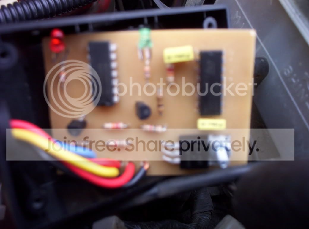
I went out, started the car, and let it warm up. I was feeling around the coil and noticed that when I bumped the wares coming out of the transistor box the idle would change. The red light on the box is normally lit and the red light shuts off when the idle drops (when bumping the wire). Im going to take a picture of the inside of the box.....
Trending Topics
Does the green one go out too? The red LED indicates the output signal. The only way the red would go out without the green going out is if the wire/trace lifted and was touching ground. If you have a multimeter, I can give a list of resistances between the different wires to check things out.
Okay, the resistances should be:
-red-red 0 Ohm
- yellow-red ~1k
- blue-black ~1k
- red-black ~6k, I think
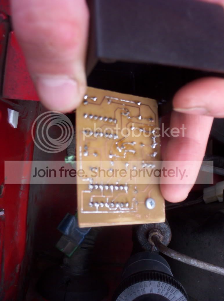
I did have to do some repairs on that board. Many of them had nealy invisible breaks in the traces where the etchant ate through. The one at the bottom of the board (top in the bottom pic) is the ground for the red LED. If this was broken, the LED could go out, but shouldn't effect idle. Then there is the trace that connects to the blue wire. If this was broken, the idle could change and the LED would go out if the break was near/at the transistor. My bet is this trace. It connects to the bottom transistor, a resistor, and then the output wire (blue). You could take some bare wire (like a resistor lead) and solder to those 3 points (transistor, resistor, blue wire) and/or resolder the transistor connection.
EDIT:
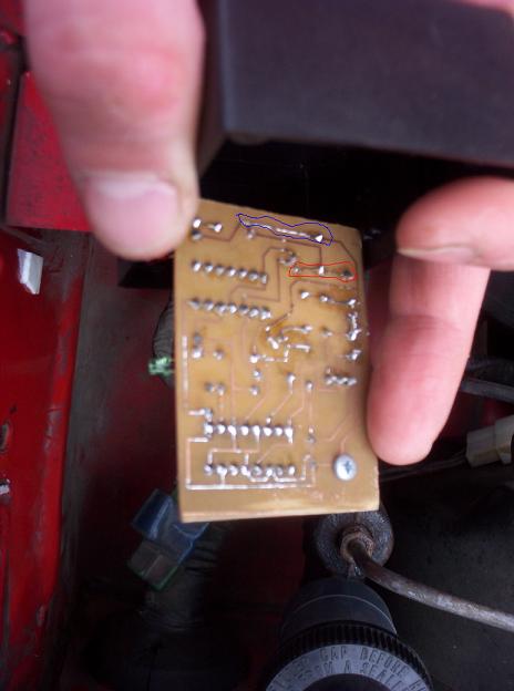
The area is circled in red. The one marked in blue would only effect the LED and not the actual output (idle).
-red-red 0 Ohm
- yellow-red ~1k
- blue-black ~1k
- red-black ~6k, I think
I did have to do some repairs on that board. Many of them had nealy invisible breaks in the traces where the etchant ate through. The one at the bottom of the board (top in the bottom pic) is the ground for the red LED. If this was broken, the LED could go out, but shouldn't effect idle. Then there is the trace that connects to the blue wire. If this was broken, the idle could change and the LED would go out if the break was near/at the transistor. My bet is this trace. It connects to the bottom transistor, a resistor, and then the output wire (blue). You could take some bare wire (like a resistor lead) and solder to those 3 points (transistor, resistor, blue wire) and/or resolder the transistor connection.
EDIT:
The area is circled in red. The one marked in blue would only effect the LED and not the actual output (idle).
Last edited by gsl-se addict; May 18, 2006 at 03:22 PM.
I poked around the board with a small razor blade and found the problem by connecting some shady looking solder points. I circled it in the attached picture. Thanks for your help!  Now, I will continue testing!
Now, I will continue testing!
That is an input. Not the output. Try doing the same with what I circled in red. Some of these boards turned out better than others. The new ones are professional, so this isn't a problem. I believe your board is one of the last ones I did. I was up to like 3:30am putting those things together the night before I flew out to France. Probably didn't get as much attention to testing/soldering as some of the others. Good luck. I am going to sign off now. Time for bed. I will take a look in the morning and see where you are at.
Kent
Kent
Glad you got it fixed. That does make sense that it could have been the problem (no input). The green LED stays on as long as there is power. It goes out when the input is pulled to ground. The output then goes high (red LED turns on). I forgot to ask you if the green LED was blinking or was just on when this was happening. I assumed it was blinking (signal getting in but not getting out). Good luck. Keep us up-to-date on how the cooler works.
Lives on the Forum
Joined: Jun 2004
Posts: 11,359
Likes: 14
From: Grand Rapids Michigan
I'm working on something similar right now. Only instead of what you did, I'm mounting a large heat sink to the ignitor housing (in between the housing and the coil).
The ignitor mounts to a plate, which has thermal paste on it to transfer the heat to the housing. So I figure the hottest point would be that spot on the housing. This is where my heatsink will go.
I thought about cutting through the housing so that I could place the heatsink right against the ignitor's backing plate, but that's way too much work. lol. If this coil pack dies on me too, then that will be my next step.
Nice work Roundabout. I'll post some pics when mine is done and maybe we can compare results...
Lives on the Forum
Joined: Jun 2004
Posts: 11,359
Likes: 14
From: Grand Rapids Michigan
Anybody know if there is some kind of an epoxy that doubles as thermal paste? I know they can glue heatsinks onto chipsets in PCs, but not sure what's involved.
If I can find something like that, then that would greatly simplify the mounting of the heatsink and keep it looking good. Not sure how I could otherwise mount it without making it look all ghetto.
If I can find something like that, then that would greatly simplify the mounting of the heatsink and keep it looking good. Not sure how I could otherwise mount it without making it look all ghetto.
Lives on the Forum
Joined: Jun 2004
Posts: 11,359
Likes: 14
From: Grand Rapids Michigan
Okay, I found some. It's made by Arctic Silver and conducts just as well as their usual stuff does. 11 bucks at http://www.newegg.com/Product/Produc...82E16835100005
I think I'll try this out and see how cool it can keep my setup. I think I'll still safety wire the heatsink, just so that if it does fall off I won't run over it and get a flat tire.
I think I'll try this out and see how cool it can keep my setup. I think I'll still safety wire the heatsink, just so that if it does fall off I won't run over it and get a flat tire.

Sorry for the long delay. I have been driving it around lately and it seems that the ignitor is keeping slightly cooler, but I don't think it is enough to prolong it's failure by too much. I will have more detailed pictures up tomorrow since I don't have any projects lined up at work I have a small heat sync I am going to attach directly to the ignitor this week so I will have more pictures and updates to come.
Justin
I have a small heat sync I am going to attach directly to the ignitor this week so I will have more pictures and updates to come.Justin
Lives on the Forum
Joined: Jun 2004
Posts: 11,359
Likes: 14
From: Grand Rapids Michigan
When I removed my ignitor from the casing, I noticed that the ingitor is attached to a metal plate. Well, the back of that metal plate was coated with heat past so that the heat generated by the ignitor can pass into the metal of the casing. I figure that the hottest point in this whole assembly is going to be on the outside of the casing where that metal plate attaches on the inside.
I just got the thermal pasted I needed to remount the ignitor in its original position. I mounted the coil pack using only two of the screw mounts, so now the coils are mounted off center which exposes the part of the casing where I will mount my heatsink. I'll post some pics when I'm done so that you will know what I mean.
I haven't gotten the arctic silver epoxy yet, so I'm just going to rig an attachment for the heatsink for now.