
Minimalist: 12A wiring


Thread Starter
Beater King
Joined: Aug 2005
Posts: 313
Likes: 0
From: Victoria BC
So I'm in the middle of swapping a 12a into my non-mazda Race car.
Backround:
Now, I'm a minimalist, I like to keep things very simple and remove pointless stuff, however, part of the issue is wiring hurts my brain. I've taken some schooling, had friends and co-workers try to explain it, read some books but it just doesn't click in my brain.
Issue:
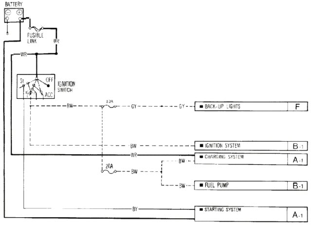
So, I've been looking through the FSM and I just want to find what wires I need to make the motor run. Obviously the distributer, starter, coils and fuel pump. However, the way the FSM is laid out is fairly confusing to me. I've gone and cut out some of the images in hopes to simplify it.
Question:
Can someone provide a final wiring diagram of just the wires needed to run the motor. On their own circuit, no 'tie ins' etc to existing circuits or whatever. Switches are nice, however I am NOT running an column ignition switch.
Backround:
Now, I'm a minimalist, I like to keep things very simple and remove pointless stuff, however, part of the issue is wiring hurts my brain. I've taken some schooling, had friends and co-workers try to explain it, read some books but it just doesn't click in my brain.
Issue:
So, I've been looking through the FSM and I just want to find what wires I need to make the motor run. Obviously the distributer, starter, coils and fuel pump. However, the way the FSM is laid out is fairly confusing to me. I've gone and cut out some of the images in hopes to simplify it.
Question:
Can someone provide a final wiring diagram of just the wires needed to run the motor. On their own circuit, no 'tie ins' etc to existing circuits or whatever. Switches are nice, however I am NOT running an column ignition switch.
You need a fuse box, high amp toggle switch and several fog lights or automotive relays.
High amp toggle switch to replace the ignition switch @ steering column.
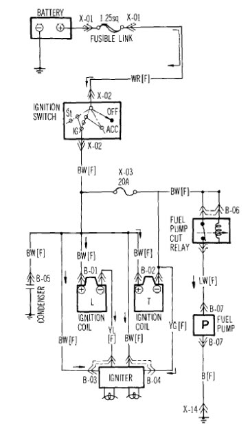
I will start with the leading and trailing coils. battery to fuse box to 30Amp relay. 97 to leading coil +, 97A to trailing coil +, 86 ground and 85 to your high amp toggle switch.
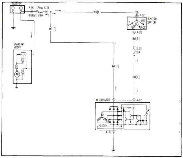
Alternator=either coils + terminal to altenator's F terminal (upper male on the 2-wire pigtail). it needs a constant 12V for it to charge.
Fuel pump and E-fan= wire it just like leading/trailing coils. 85 to a coi;s + or a toggle switch.
Starter = same as above except you need a push button switch instead of toggle switch.
High amp toggle switch to replace the ignition switch @ steering column.
I will start with the leading and trailing coils. battery to fuse box to 30Amp relay. 97 to leading coil +, 97A to trailing coil +, 86 ground and 85 to your high amp toggle switch.
Alternator=either coils + terminal to altenator's F terminal (upper male on the 2-wire pigtail). it needs a constant 12V for it to charge.
Fuel pump and E-fan= wire it just like leading/trailing coils. 85 to a coi;s + or a toggle switch.
Starter = same as above except you need a push button switch instead of toggle switch.

Wow.... thanks for the info guys. I am going to be doing the same thing in a Lotus Super 7 that I'm building an engine for... for one of my friends. Disco, if it helps... we're planing on using one of the EZwiring.com kits. To, hopefully simplify the procedure. I think wacky has used them as well in the past. Haven't installed it yet, but definitely seems like a high quality kit.
Thread Starter
Beater King
Joined: Aug 2005
Posts: 313
Likes: 0
From: Victoria BC
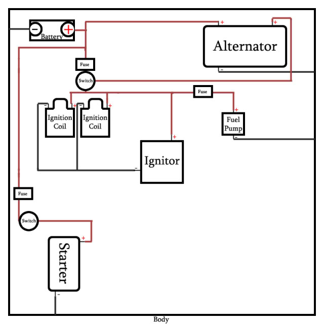
Hmmm, I apologize for my lack of understanding Wacky Ricer. I've done this drawing in hopes to keep it simple.
A switched 12v to the starter on it's own little circuit from the battery.
A switched 12v to the coils, as well as to the positives on the condenser. The coil grounds go to the condenser as well. This same switch sends 12v to the alternator and to a fuse to the fuel pump.
A single 12v feed to the other 12v input on the alternator.
Questions:
1. Does this diagram seem correct?
2. What is a condenser?
3. Why do I need this condenser?
4. Why do I need a relay?
Again, I apologize for my lack of knowledge.


I would add the automotive relays to your circuit above like Wacky suggested. I would also consider getting a second gen or similar fuse block for the alternator and high amp circuits.
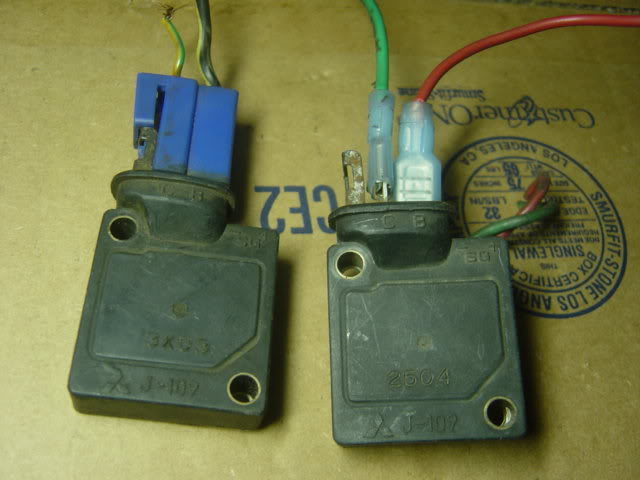
here's a pix of a stock igniter and factory wire (refer to pix in left). so when you're wiring the igniter, be sure to remember which is which. The black/white stripe is your 12-V while the yellow/blue or green stripe goes to the coil's negative terminal.
You can wire it just like in your diagram. However, since you still need to run a wire from coil negative to igniter, why not run the igniter's 12-V directly from the coil positive? IMHO, it will make it a cleaner install at the same time, easier to trouble shoot.
also, why do you need a condenser?
You can wire it just like in your diagram. However, since you still need to run a wire from coil negative to igniter, why not run the igniter's 12-V directly from the coil positive? IMHO, it will make it a cleaner install at the same time, easier to trouble shoot.
also, why do you need a condenser?
Trending Topics
Thread Starter
Beater King
Joined: Aug 2005
Posts: 313
Likes: 0
From: Victoria BC
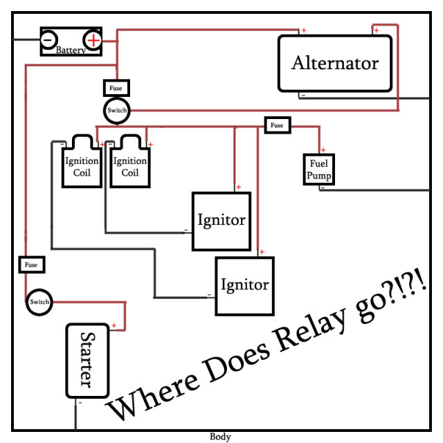
Revised my design a bit.
Still have unanswered questions.
1. Why would I need a relay?
2. Is it fine to combine the leading and trailing coil grounds to the igniter?
3. What gauges of wire are needed for what? I think I only need a large Gauge for the starter positive.
4. What size fuses are needed?
Updated drawing.
Still have unanswered questions.
1. Why would I need a relay?
2. Is it fine to combine the leading and trailing coil grounds to the igniter?
3. What gauges of wire are needed for what? I think I only need a large Gauge for the starter positive.
4. What size fuses are needed?
Updated drawing.
Relays are desirable so that you are not trying to pass 40-50 amps of current through a switch... they will take the load off of the switch. The other issue you have with your diagram is that you will have a leading and trailing ignitor and they will be wired to there respective coils... the negative signal from the ignitors grounds the coils which causes them to fire.
See my initial post on where/how to use a relay. If I am to re-wire your car, there will be 1 relay to control both ignition coils, and a relay for fuel pump, e-fan and starter. Remember:
30 = fuse box to relay
86 = ground
85 = switch or 12V wire when the ignition switch is ON (85 and 86 can be reversed, not a big deal since this is low-voltage).
87 or 87A = positive terminal of coil, e-fan and starter's solenoid.
Wiring wise:
Battery to fuse box: no less than 12g (i use the wire for installing AMPS)
Ignition coil to ignitors: 16g.
All others 14g.
and once you get to 110V/220V residential A/C and 3-Phase commercial A/C units, they are called "contactors," not relay. It is easier/cheaper to replace them than the compressors and motors.
ideally you should have a relay on every component that draws a fair ammount of current.... it is not needed on the solenoid... but as Wacky said you should have one for the ignition... one for the fuel pump.... alternator shouldn't need one as it's just a field voltage signal and doesn't pull much current....
basically use the same wiring diagram.... but add a relay between the battery and the above mentioned parts.... then use the 12v switched signal to trigger the relay... this will give you full consistent 12v from the battery, and keep the current draw away from your switch/ignition.
If I was more skilled with paint i'd draw a diagram....
lol, funny that I'm the same way. I rather use VISIO for diagrams but I cant find my CD an I suck in "paint"
good point. Buy a breaker and install this between the battery and the fuse box (between 6-12" from battery). A 150amp should be less than $50 bucks and If Im not mistaken, Autozone sells the 100amp for apprx $30.
And if you can, grab the 40amp relays but a 30amp will do.
good point. Buy a breaker and install this between the battery and the fuse box (between 6-12" from battery). A 150amp should be less than $50 bucks and If Im not mistaken, Autozone sells the 100amp for apprx $30.
And if you can, grab the 40amp relays but a 30amp will do.
Honestly when I was removing wiring on the race car, I got out the factory shop manual and started cutting anything that didn't let it run.
Be sure to start the engine after some cutting. And, everyone is right use relays when necessary. A push button temp closed circuit switch for the starter is real nice.
A circuit breaker after the battery, before the fuse box is a great idea. There is an 8 gauge white with red stripe wire to breaker. And, now is a good time to upgrade that wire to a proper 6 gauge cable. That wire is typically crispy and falling apart.
while ordering parts @ summittracing, I came across a couple of info that will help you with your project.
http://www.summitracing.com/expertad...p=techarticles
http://www.summitracing.com/expertad...p=techarticles
http://www.summitracing.com/expertad...p=techarticles
http://www.summitracing.com/expertad...p=techarticles
Thread Starter
Beater King
Joined: Aug 2005
Posts: 313
Likes: 0
From: Victoria BC
Hope this version is besterer? I think I've got it now. I'll have to reuse some factory automotive relays. Pretty poor. 
Please let me know if there is any issues with this drawing. Thank you for all the help guys!
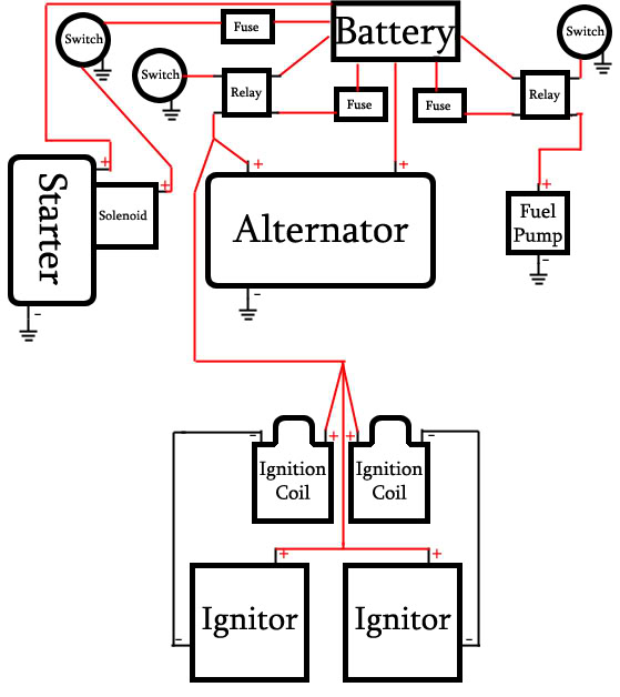
Please let me know if there is any issues with this drawing. Thank you for all the help guys!
That diagram looks spot on... i smell an archive !!
You could simplify it by running a single switch for the FP and ignition.
In this case you would be using the switched 12v to trigger the relay.
You could simplify it by running a single switch for the FP and ignition.
In this case you would be using the switched 12v to trigger the relay.
Your alternator should have an internal regulator... that controls the load. The 12v switched is the field charge... basically voltage to the outside copper coils inside of the case. Alternators increase output as RPM increases so the voltage should vary with driving. Long story short... i wouldn't worry about it.
I just ordered these for another project. I feel that these will help you make a clean install
http://www.wiringproducts.com/contents/en-us/p3990.html

http://www.summitracing.com/parts/PCO-5591PT/. best price Ive seen so far. for $5, it comes with a 40amp relay and relay pod/connector I ordered 5 of them
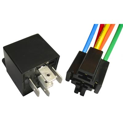
http://www.wiringproducts.com/contents/en-us/p3990.html
http://www.summitracing.com/parts/PCO-5591PT/. best price Ive seen so far. for $5, it comes with a 40amp relay and relay pod/connector I ordered 5 of them
Thread Starter
Beater King
Joined: Aug 2005
Posts: 313
Likes: 0
From: Victoria BC
I just need a little more help. Sorry for the old bump.
I'm looking at my ignitor, it has a C and B, not sure which is negative, and which is positive.
Also. I'm not sure if my alternator is stock or not, but it has 3 posts all unmarked. one is huge, so it's obviously the constant 12v feed, the other two are not marked and look identical. I canot determine which does what.
Someday I may be asking about "minimalist 13B fuel injection wiring".
This may sound simplistic, but make sure you have very good grounds, including the engine block to the frame. I remember no being able to start the engine when a ground or two were poorly contacted.