
Improving A/C - Heater Flow??

Thread Starter
Sin City Rotary
Joined: Sep 2009
Posts: 1,707
Likes: 2
From: Las Vegas
Improving A/C - Heater Flow??
Ok I have the A/C working very well in my SA, vent temps in the 40's vs the vent temps of 65 in my DD this was done in the afternoon at about 105 degrees. Classic R12 vs R134A.
But here is where I am stumped, I have already changed my blower motor as it blew the fuse when ever I put it on (for heat). But the flow from the dash vents is weak can barely tell it's on. My goal is to be comfortable and have to turn it down because I am getting cold lol.
Has anyone experienced this?
Has anyone been able to improve the flow?
thanks
Mine flows quite a bit of air, even on the low fan speed setting. If you haven't already then I would check to make sure the flaps on the heater box are working correctly and it isn't just blocking them all off or something. Even with my cobbled together A/C system running R134a I only need the low speed setting to be fine.


Joined: Mar 2001
Posts: 31,833
Likes: 3,232
From: https://www2.mazda.com/en/100th/
possible the blower motor is weak? they ARE really old. even good ones don't move as much air as like a modern car. the FC book has a chapter on how the big the blower motor is.
oh and also there are seams between the blower and evaporator, and the evaporator and the heater box, these are sealed with foam, and if the foam is gone the air won't make it out of the dash
oh and also there are seams between the blower and evaporator, and the evaporator and the heater box, these are sealed with foam, and if the foam is gone the air won't make it out of the dash
Thread Starter
Sin City Rotary
Joined: Sep 2009
Posts: 1,707
Likes: 2
From: Las Vegas
Mine flows quite a bit of air, even on the low fan speed setting. If you haven't already then I would check to make sure the flaps on the heater box are working correctly and it isn't just blocking them all off or something. Even with my cobbled together A/C system running R134a I only need the low speed setting to be fine.
appreciate the input
Last edited by 13x; Aug 16, 2011 at 09:08 PM.
Thread Starter
Sin City Rotary
Joined: Sep 2009
Posts: 1,707
Likes: 2
From: Las Vegas
possible the blower motor is weak? they ARE really old. even good ones don't move as much air as like a modern car. the FC book has a chapter on how the big the blower motor is.
oh and also there are seams between the blower and evaporator, and the evaporator and the heater box, these are sealed with foam, and if the foam is gone the air won't make it out of the dash
oh and also there are seams between the blower and evaporator, and the evaporator and the heater box, these are sealed with foam, and if the foam is gone the air won't make it out of the dash
Will check it out as well
Last edited by 13x; Aug 16, 2011 at 09:10 PM.
Thread Starter
Sin City Rotary
Joined: Sep 2009
Posts: 1,707
Likes: 2
From: Las Vegas
Well I'll be after gettign might not so young not so slim butt under the dash there was air escaping and blowing towards the firewall .... fixed still seems kind of week thou ......
There is a jumper wire that needs to be installed on the resister mounted on the fan whenever a/c is added. It is designed so to speed up the fan to compensate for the added "back pressure" of the a/c evaperator coil. You need to check to see if your resister has the jumper, if not adding one will boost the speed and provide more air at the vents.
Trending Topics
Thread Starter
Sin City Rotary
Joined: Sep 2009
Posts: 1,707
Likes: 2
From: Las Vegas
There is a jumper wire that needs to be installed on the resister mounted on the fan whenever a/c is added. It is designed so to speed up the fan to compensate for the added "back pressure" of the a/c evaperator coil. You need to check to see if your resister has the jumper, if not adding one will boost the speed and provide more air at the vents.
electrical is my least favorite thing even on these super simple cars
thanks
I do not have a picture of the jumper but here is a pic of the resister.
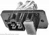
It is located on the back of the fan housing where the wiring harness plugs into the fan housing. The jumper would plug into the two lugs that are hidden in this pic by the foam plug. Just make a jumperout of fairly large wire and two female spade connectors and plug it in. You will probably have to remove the fan housing to get to the resister, but its not that hard to get it out.
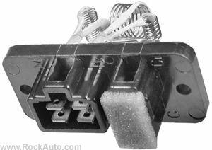
It is located on the back of the fan housing where the wiring harness plugs into the fan housing. The jumper would plug into the two lugs that are hidden in this pic by the foam plug. Just make a jumperout of fairly large wire and two female spade connectors and plug it in. You will probably have to remove the fan housing to get to the resister, but its not that hard to get it out.
I do not have a picture of the jumper but here is a pic of the resister.
Attachment 439334
It is located on the back of the fan housing where the wiring harness plugs into the fan housing. The jumper would plug into the two lugs that are hidden in this pic by the foam plug. Just make a jumperout of fairly large wire and two female spade connectors and plug it in. You will probably have to remove the fan housing to get to the resister, but its not that hard to get it out.
For note: on the resistor pack, terminals are L,M,H1,H2 and C1,C. On the wiring diagram they use L, M1, M2, H. I assume that L=L, M=M1, H2=M2, H1=H, based on the wiring of the resistor.
I cannot find a diagram that shows the connectors that you refer too but when I look at the 85 wiring diagram it shows the jumper I mentioned. It appears to me that there is a small resister that is in the circuit between the resister set and the motor that is bypassed by the jumper. There are three additional resisters that slow the motor for the lower settings but the fourth is in the circuit in all settings, unless it is jumped. When I put my jumper in it did increase the speed of my blower.
Thread Starter
Sin City Rotary
Joined: Sep 2009
Posts: 1,707
Likes: 2
From: Las Vegas
I cannot find a diagram that shows the connectors that you refer too but when I look at the 85 wiring diagram it shows the jumper I mentioned. It appears to me that there is a small resister that is in the circuit between the resister set and the motor that is bypassed by the jumper. There are three additional resisters that slow the motor for the lower settings but the fourth is in the circuit in all settings, unless it is jumped.
But the previous post is valid for an early (4/78) SA?
I going to say yes. In fact mine is an early SA and it has the place for the jumper so I assume that they all have it. That having been said the 79 wiring diagram does not show it. If yours does not have a resister set that has a place for it you can replace the resister set with one from Black Dragon, which I know will have it. They are interchangeable.
From looking at the guts from a late model unit, there is a Green wire coming from the 2 pin connector to the motor. I think this is the motor drive wire. Currently, on a non AC car, this wire goes to the C1 terminal, thus passing through the resistor. If one was to switch the wire to the C terminal in the same connector, the additional resistor would be bypassed. Does your jumper retain the wire in C1, while connecting C1 to C? In this configuration, the motor speed would increase as the resistor would be bypassed.
The way this resistor bank works is:
Terminal L = current must pass through 4 resistors to C1
Terminal M = current must pass through 3 resistors to C1
Terminal H2 = current must pass through 2 resistors to C1
Terminal H1 = current must pass through 1 resistor to C1
Terminal C = current must pass through 1 resistor to C1
If one was to connect the motor to C instead of C1:
Terminal L = current must pass through 3 resistors to C
Terminal M = current must pass through 2 resistors to C
Terminal H2 = current must pass through 1 resistor to C
Terminal H1 = current must pass through 0 resistors to C
I don't know how this would function with just the 4 pin connector. Where would the motor lead come from? How would the extra resistor come into play? Just jumpering the two C terminals together would do nothing.
EDIT:
It would seem that according to the wiring diagrams, the 79's may not have a jumper as they don't have AC listed. 81-83 have a jumper that can be added and 84-85 require the position of the wire in the connector to be changed.
Last edited by Sgt Fox; Aug 17, 2011 at 03:21 PM.

Thread Starter
Sin City Rotary
Joined: Sep 2009
Posts: 1,707
Likes: 2
From: Las Vegas
Mine? Didn't think of taking a pic, I had to put the car back together as we have our local club meet tonight and the the "monthly rotory meet" with the 8's Friday night
It was molded but did not have the male connectors there to jump errrr
It was molded but did not have the male connectors there to jump errrr
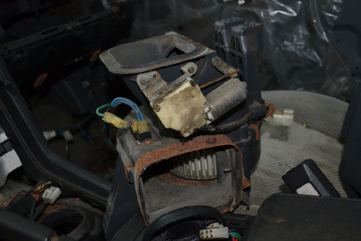
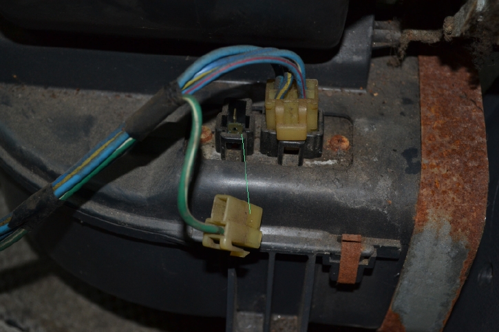
Here's what my 84's with AC have. Resistor is on the rear of the blower motor box. The green line shows where the jumper was. 3" Green wire with plugs on each end. Not in the picture because it is heading for Victoria, BC tomorrow.
Thread Starter
Sin City Rotary
Joined: Sep 2009
Posts: 1,707
Likes: 2
From: Las Vegas
super awesome thanks for the pictures!!
yup only thing is mine did not have the male spade terminals
I turned the fan on while I had it down crap if the air from the vents felt the same way I'd be super happy, but it doesn't ;(
yup only thing is mine did not have the male spade terminals
I turned the fan on while I had it down crap if the air from the vents felt the same way I'd be super happy, but it doesn't ;(

Thread
Thread Starter
Forum
Replies
Last Post
Turblown
Vendor Classifieds
12
Oct 17, 2020 03:25 PM