When you click on links to various merchants on this site and make a purchase, this can result in this site earning a commission. Affiliate programs and affiliations include, but are not limited to, the eBay Partner Network.
Looking at the wiring diagram for my '85 12a, there are three fusible links between the battery and the the rest of the electrical system. The alternator is connected on the other side of the largest fusible link rather than directly to the battery. This seems to contradict most modern systems that place the alternator and battery on one side of a main fuse and everything else on the other.
I'm adding some relays and circuits to my car and I want to wire everything right without disrupting the original harness if I don't have to.
My question is, can I remove the White/Red wire that goes between the alternator and the engine harness on the driver's side, and instead run a wire directly from the alternator to the battery? Then I will add my circuits off the battery.
To explain this a little better here is the current flow now...
Most accessories: alternator generates power which travels through White/Red wire to ignition switch to fuse panel and to accessory.
Headlights: alternator generates power which travels through White/Red wire to 1.25sq fusible link. It passes through that fusible link, then through 0.3sq fusible link and on to headlights.
Current flow after my change...
Most accessories: alternator generates power which travels through new wire to battery, then from battery to 1.25sq fusible link. It passes through fusible link to White/Red wire to ignition switch to fuse panel and to accessory.
Headlights: alternator generates power which travels through new wire to battery, then from battery to 0.3sq fusible link and on to headlights.
I wouldn't connect alt output directly to battery,any short to ground alternator failure or a rub thru or some catastrophic failure to that unfused wire going directly to battery will cause severe damage to alt diodes,wire meltdown,possible fire and or battery implosion,the latter you do not want to happen to underhood area of a nice car.. I don't know any modern cars off top of my head with that arrangement,with all onboard electronics on modern cars a failure like i described would total the car just from damaged electrics/electronics if not burn the car to the ground. A lot of cars have 150-200 amp alternators from factory and with this much available amperage shorted to ground,extensive damage surely to result.
The way your car is wired originally is correct way to do this. The only unfused feed wire in the car is the short section from positive battery clamp to main fuse link. This protects everything else in the car downstream from main link and covers possibility of alternator failure or output wire being shorted to ground, no drama,no damage to anything downstream of main fuselink.
Not certain your reason for rewiring alt output wire. Are you installing a higher capacity alternator?If that's the case,decommission,remove this wire if you want to and from your new alternator run an appropriate gauge wire dependent on amp capacity 6-8 gauge over to the fenderwell or close to the battery,closest to battery is best. A high amp fuseholder and a short section of same size 6-8 gauge feed wire from positive battery clamp to fuseholder. What ever the output of alternator,install a main fuse 10-20 amps higher than output rating to cover the possibility of car being jumpstarted with a dead battery and alt charging battery at its max output. Connect everything you want to add accessory wise on fused side of fuseholder with alt output wire and add fused individual circuits for each component(s) being powered. May want to add a bussbar fed from fused side of main fuse holder to keep connections to a minimum(alt and accessory feed to bussbar) and connect whatever components you wish to feed from bussbar. Make sense?
You can leave all original wiring in car from battery feed wire to fuselinks undisturbed.
Maybe I should clarify, I'd be adding a higher amperage main fuse between the battery and fusible links and the alternator would be connected to this (between the new main fuse and the fusible links).
The only change from stock is that all current from the alternator would flow through the fusible links where as it doesnt now. They simply serve as protection from battery, not the alternator.
I can't understand what you're trying to do here,if alt is stock output nothing to be gained by what you're proposing,just redundant wiring. Where alt is originally connected to main fuse link it both recharges battery and feeds all fuselinks and subsequent wiring from there.
The fuselinks serve to protect wiring back to battery to stop any further damage from shorts by melting and opening circuit before that happens.The only fuselink that will melt in event of alternator or its power wire shorting is main link.
I think you're looking at current flow backwards,the fuselinks are there to disconnect the affected circuits FROM the battery to prevent further damage,alternator included.
I am upgrading to an FC alternator. I am adding a separate relay/fuse box with the following:
1 35a relay for fuel pump to a 30a fuse then to the fuel pump.
1 35a relay for EFI related stuff to a 20a fuse for ignition coils (direct fire), a 10a fuse for O2 sensor, a 5a fuse for injectors, a 5a fuse for other misc EFI stuff
1 20a fuse for constant power to ECU.
This box needs constant battery power and since the power demands of the coils will be higher than stock, I'm not sure the best place to connect it. All documentation for IGN-1A coils say to connect them directly to battery. Is that literal or figurative?
I have not cut the original white/red b-post cable attached to the alternator yet. It is joined to the white/red cable that runs between fusible link box and ignition. I am concerned about the flow of current for these coils and I don't want electrical feedback/noise disrupting the rest of the system.
What if I just did this. Place a post in the engine bay. Take original white/alternator wire and attach it to the post. Attach a new wire and run it to the alternator. Attach the feed wire to my new fuse box. All of this would be protected from the battery via the fusible links and I won't have to cut any original wires.
The only concern with this approach is that the original fusible link may see more current than intended during startup. The other downside is that if the coils need power from the battery, it has to get it through that old wire.
I would just replace the fusiable link block with a second gen fuse holder. The way I did mine was to take a hammer and crush the fusiable link block. This exposes the connectors and they will fit the second gen fuse block.
I know you don�t want to go the 2nd gen fusebox route,I remember from your other thread.
Also know you want a clean install AND want to preserve the integrity of original wiring from fuselinks back.
You could just connect your FC alternator to original white/red wire and that would work...but wouldn�t allow higher amp alternator to deliver all its output to electrical system,which is the whole point of upgrading in 1st place,due to the smaller gauge wire that was suitable for the original lower amp alternator.
Go back and look at my prior post suggesting a proper solution for both integrating a larger amp alternator and providing a solid power source for everything you wish to add to the car without tapping into original electrical system.
Allows removal of your upgrades with no evidence of them being there if you should wish to return car to original condition as you�re not touching/modifying original
wiring.
I service and work on several customers classic cars and do upgrades like more power for better headlamps,FI conversions,etc while keeping originality in the forefront. Minimal intrusion into original electrical system and ability to return car to as before status.
Different vehicles need a different approach.
All installs need to be professional and of the level of oe or better so as not to devalue vehicle.
Done several 1st gens of my own and for customers that have been on the road for years. What i�m suggesting to you is least complicated,cheapest way to go about what you need while being a tidy install that�s low key and not attract much attention.
Happy to hash this out further with you if you�d like.
It sounds like you under stand my thought process. Minimally invasive changes as to not render the factory wiring diagrams useless...but upgrades for power and EFI. I'm not doing a "wire tuck" or anything. I don't like messing with wiring that is working just fine.
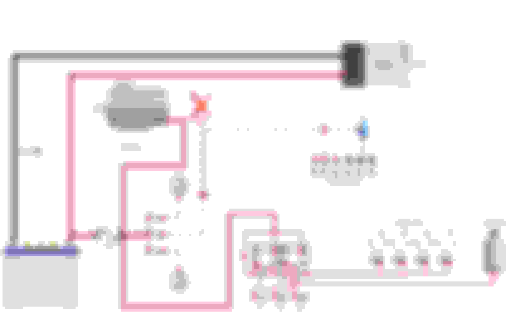
Anyway, I'm not sure I completely followed your suggestion, but here is my other thought on how to do this (see photo below). The catch being, that power will always pass through the fusible link for all OEM electronics. Maybe that's not bad, I don't know. Before I started this the car had a few electrical gremlins (sporadic seat belt light flickering on and off, and more recently the HVAC controls weren't working right, and very low voltage with lights, wipers, and rear defroster on. I chalked it up to bad grounds which I intended to fix and clean while working on this.
One of the reasons the power windows and light don't work very well is that the wiring goes through the ignition key wiring. The way to fix this is to add relays and use the original wiring as the trigger for the relays.
Correct about the power windows, incorrect about the lights. Those go through the combination switch (which is why they stay on regardless of ignition position). I'm eventually going to switch to LED headlights.
Correct about the power windows, incorrect about the lights. Those go through the combination switch (which is why they stay on regardless of ignition position). I'm eventually going to switch to LED headlights.
The ignition switch IS part of the combo switch. it's all one unit. It's a multi-function switch. So with the combo switch off, current is still part of the switch, just not going through those contact. This is why relays help.
The ignition switch is definitely a culprit in the aging electrical system, and the ignition relays like KC mentioned are a great addition (I was actually just reading through that thread a couple days ago). I can attest that the ignition switch does get sketchy - I've rebuilt mine once and I can still get the idiot lights to flicker if the key is so much as touched.
That latest wiring diagram you posted is essentially how I did my FD alt swap. I ran the alt to the battery and then a new lead from the battery to the fuse-able link box. I did have to cut two wires for the FD alt sense wire, but otherwise everything else is OEM. One difference though is that I have relayed headlights and ignition system (DLIDFIS w/ HEI), along with some other accessories that tap into power before the box (ie. my sub) so that they aren't using the old harness at all and also bypass the ignition switch. It's a bit of a mess - which the neat side of me says I need to deal with badly - but it works well and doesn't jeopardize any original wires. The original alt line can be unplugged near the firewall (as I assume you have figured out already), although I additionally chose to de-pin the line and put the now blank connector back onto the harness side just as an extra precaution since the line is still live. The FC alt has the added bonus of not having to splice a new sense/check relay plug, so no wires should need to be cut.
Looking at your latest wiring diagram,i agree with most of what you did there with a couple exceptions...keep the new circuit you're adding for the alternator output wire and fuseholder to battery separate from 3 underhood fuselinks as in don't jumper the two together.
The original wire that runs from positive battery clamp to feed power to the fuse links is sufficient for the load of original systems in car.Whatever improved voltage/amperage the new alternator provides will go to the battery where the feed wire for fuse links will enjoy the increase and supply that increase to all systems in car. Remove the original white/red alternator output wire or at least disconnect it at fuse link end so it is no longer live.
Treat your power feed from 80A fuseholder as if it is coming straight from the battery. Don't depend on that 80A fuse to protect your downstream wiring. Its main function is to melt should there be catastrophic alternator failure or the output wire from it somehow is damaged and shorted to ground to prevent a fire or battery damage. You should fuse the load feed on each relay #30 terminal. Should there be a problem with the circuits each relay controls,much damage will be done before the 80A fuse will melt. 30 amp fuse for each relay is a good compromise between being enough to supply a good amount of current yet will melt quickly should some type of short event occur.
Looking closely to how your relays are wired,you can see that they're energized as soon as battery voltage is provided to the circuit. The jumper from #30 terminal to #86 terminal ensures the relay(s) will be on 100% of the time even with engine off and key out of ignition.
Relay terminal legend: #30=power to relay
#87=switched supply to load
#85 relay ground
#86 switched voltage trigger to energize relay
A suitable source of trigger voltage for #86 would be black/yellow wire from ignition switch that originally supplied 12 volt feed to coils/igniters in crank/run positions and 0 voltage when ignition shut off. This will turn off relays as soon as key is switched off.
The low voltage,dim headlights,slower wiper speed,lessened HVAC blower speed when all these were turned on with defroster grid added to the equation were all complaints when these cars were new as the charging system was only adequate and at idle/low rpm engine speed the car is using power from the battery to make up for the deficit of current supplied by the alternator-like all cars from that era,not just Mazda. At 30+years of age add in increased resistance from oxidation and corrosion in vehicle wire harness which does not help the original situation where the harness didn't carry one more strand of wire than absolute minimum. This is much worse in modern cars of today.
This is reason swapping in later generation higher amp alternators to FBs to try to improve the voltage deficit. In your case i would have chosen an FD 90 amp alternator as what you're adding to your car will eat up some of increased power the 70 amp FC unit will supply and not leave you with"enough"reserve for fully loaded electrical system at low engine speeds. I realize you're tracking the car and won't be using all accessories while doing so but assume you're driving the car on the street as well and will encounter darkness,rain,cold...
What exactly are your HVAC controls doing or not doing? The system in 84-85 cars worked well but had some pattern failures.
First off, thanks so much for going over this with me. I've been milling over this in my head for months and it's nice to bounce ideas off someone.
Originally Posted by GSLSEforme
keep the new circuit you're adding for the alternator output wire and fuseholder to battery separate from 3 underhood fuselinks as in don't jumper the two together.
The original wire that runs from positive battery clamp to feed power to the fuse links is sufficient for the load of original systems in car.
The original wire for this is attached to the original terminal post and screws onto the fusible link box. It's getting replaced regardless and I don't see how it makes a difference whether this cleanly connects to the 80a post or the battery post. I don't want a ton of wires coming off the battery. Side note: I'm not relocating the battery yet. It's still going to be street car and i actually use my storage bins.
Remove the original white/red alternator output wire or at least disconnect it at fuse link end so it is no longer live.
I drew an X on the diagram where it won't be connected to the alternator anymore. This wire is hard spliced into the wire between the fusible link and ignition...at least I think it is, I haven't unravelled the rest of the loom to see where the two connect.
You should fuse the load feed on each relay #30 terminal. Should there be a problem with the circuits each relay controls,much damage will be done before the 80A fuse will melt.
Noted, this was something I was unsure of, I can move the connections around so #30 pin connects to fuse and #87 goes direct to device.
Looking closely to how your relays are wired,you can see that they're energized as soon as battery voltage is provided to the circuit.
Not correct, only because I didn't put in the rest of the wires to show you what's going on. These relays are not grounded to earth via pin #85, they are connected to an AUX input on the ECU. The ECU will activate them by closing the circuit to ground which will prime the fuel system and power up the injectors. If the crank angle sensor doesn't report back at anytime, these relays are disabled.
I can, however, use the original black/yellow ignition wire to provide power to #86 and actually I have it that way on my larger complete wiring diagram I am working on (that's where these smaller diagrams are getting copied from). That puts the relays in a double protection. Must have power from key, and ECU must give the all clear.
In your case i would have chosen an FD 90 amp alternator
This was more a decision of price and convenience, I'm pretty sure the one I picked was an 80 amp version (turbo2 maybe?), it was the most powerful one that used the same harness connection, and it cost less than the FD alternator. I know people on here have used Ford Taurus alternators and stuff but I wanted something I knew was designed for the RPMs I'd be hitting at the track.
What exactly are your HVAC controls doing or not doing? The system in 84-85 cars worked well but had some pattern failures.
I forget the specifics on which modes but it is something like this: it won't go from heat to vent. If you press the button, it lights up and you start to feel air come out, but when you release the button it goes back to heat. I think defrost worked fine though. All I remember was one mode didn't work. It happened a few times in October and then I pulled the motor for my upgrades.
One other item of concern not covered yet is the electric fan. I'm reading these instructions literally in that this particular device has its own circuit breaker and MUST be connected directly to the battery.
There are a few advantages to the Derale fans that come with the PWM. They can run at any speed and stay quiet when only a little bit of cooling is necessary, they come with their own sensor, and you can override that sensor for A/C or in my case I'll be monitoring temps from my own coolant sensor. If I pull off the track and the car is still hot, it will continue to spin until the water temp cools down even after I turn off the car.
I drew an X on the diagram where it won't be connected to the alternator anymore. This wire is hard spliced into the wire between the fusible link and ignition...at least I think it is, I haven't unravelled the rest of the loom to see where the two connect.
Yes, that is correct. The WR wire runs from the alt and then splices into the line that runs from the fuse-able link box to the ignition switch. That's the wire I had mentioned removing the connector for to deadhead it.
Regarding original supply wire from battery to fuselinks,again suggest you leave source voltage for fuselinks attached to battery in original configuration. I realize you'd think there be gains to feeding fuselinks directly from your new alternator output circuit.
The reason for recommending this is the same reason the fan manufacturer mandates fan controller be connected directly to battery,to minimize or prevent any spurious signals coming into power supply of fan controller. Even though generated power from any alternator is converted from AC to DC there is a measurable amount of AC ripple that remains in circuit. The more load alternator is placed under,the frequency and amount of ripple increases. The battery acts as a filter and damps the majority of leftover AC ripple.
Hooking the fuselinks directly to alternator circuit may introduce some amount of AC voltage into your cars original systems and may cause some issues in gauge readings,audio system "noise" and some other as yet unknowns.
Pursue removing remains of original alt output wire.
You didn't supply input info for #85 terminals. I thought they might be ecu switched but didn't want to assume.
80 amp alternator should help power requirements,bump main fuse to 100 amps.
Sounds like problem isolated to vent switch...does light remain illuminated when you release button,still click when pressed,do all other switches in HVAC panel work properly including recirc button?
With key on,engine off can you hear mode motor cycling to vent when button pushed and then cycling back to heat when button released? Do other modes work properly,Defrost,Recirculate.
Mode motors in these cars have some pattern failure issues,most can be repaired. Repairing is easy part,getting out and back in without removing complete HVAC unit is pretty difficult but can be done. Could be the vent switch has a mechanical problem,does it click like the others. If switch is determined to be the fault,much easier to swap in another mode control board.
Not really concerned about it right now, I'll worry about diagnosing it once I get the rest of the car running.
So my next question as I create this diagram is related to grounds.
Factory setup...
Large gauge wire runs from battery negative post to starter motor negative post. Along the way it also bolts to the driver's side fender. In addition to that same spot on the driver's fender, the chassis harness also grounds to the passenger fender, two spots under the dash, and a spot in the rear hatch. I do not see any connection between the motor and the battery other than the cable to the starter...if that even counts. What path does the current take when the alternator is charging the battery?
As for new grounds I have the following...
Fuel Pump: Can I ground this to the the driver's fender where the large gauge wire will take it the rest of the way, or should I run it all the way to battery?
Electric Fan: As mentioned above this will definitely go right to battery
ECU: I plan to ground this directly to engine
O2 Wideband: I plan to ground this directly to engine
Injectors, sensors, etc: I plan to use sensor ground lead on ECU
IGN-1A coils: One ground will go to the ECU, one will go to corresponding rotor housing, and the last I was going to run to driver's fender or engine or battery? I wasn't clear on the best spot for this.
Factory setup also used a condenser/capacitor ground on the motor, do I need something like this in my setup?
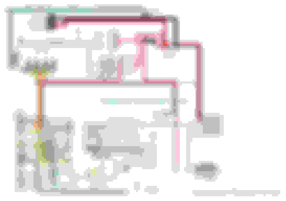
Here's where I'm at. Just need to finalize the ground wires as mentioned above and I will have a harness that plugs and plays, replacing the OEM Emissions computer with an Adaptronic 440d and reusing the factory harness. It's about as PnP as you can get.
Large gauge negative battery cable is the only ground in the electrical system,grounding 1st at drivers fender apron and then to starter motor mounting bolt. You can do a voltage drop test on both positive and negative battery cables by cranking the engine with the starter and checking for resistance. It is important that connection at fender apron and at starter be clean,shiny and corrosion free. I feel for a mostly stock electrical system on a FB is sufficient. There are many on here that will disagree with me on this and insist on adding multiple grounds to body,engine.
I've been working on these cars for a long time,since they were new. I will place the number of clutch jobs done on 1st,2nd gen to be in excess of 200,i bring this up because of what i do while performing this service. While trans was out i cleaned up the mating surfaces of engine and trans,the mounting pad for the starter on the transmission and both the positive and negative battery cables at the starter til all were shiny. Coated cable terminals with vaseline to slow down oxidation. On pretty much every car on startup,the starter spun audibly faster,a lot of cars fired up with less time on the starter. In diagnosing/repairing low charge rate complaints,for the most part,the same is done and can improve charging rate at battery between .5-1.0 volt,occasionally more dependent on level of corrosion/oxidation. Went a long way to alleviating dim lights,low voltage indicated on dash voltmeter.
If you're looking to be thorough in building your new electrical system,take the time to clean up both ends of battery cables and the crimped lug at fenderwell on negative cable,chase the threads on mounting bolt for ground lug and clean lug til shiny copper.Take steel wool and clean paint from right around mounting hole to give base of ground lug a bigger contact patch than just mounting bolt head and threads in nutsert. Before reassembly,paint ground lug all around with vaseline with an acid brush,same with mounting bolt and spot on fender you cleaned up.
I do the same on battery posts/clamps. After a couple hours of driving,underhood heat causes the vaseline to thin and flow into all the nooks and crannys of connections.Same with all new electrical connections in circuits i add to a car. Since air cannot get to the metal connections they will not oxidize/corrode for some time. There are different anti corrosion compounds available,but vaseline is cheap.This will keep the integrity of your electrical system sound for some time and why i feel extra grounds aren't really necessary until you start installing high output alternators or serious audio equipment.
Complete alternator circuit consists of output wire going,in your case to larger fused wire to battery and negative side of circuit starts at starter/trans housing,to engine to case of alternator. Not til you get into upwards of 150+ amp alternators will you need a ground cable from alternator to battery. I have a FD alternator i upgraded that puts out 136 amps on my SE and with attention to all underhood ground attachments as noted above,no further grounds are necessary.
Regarding fuel pump ground,the ground wire should be same size as power feed to pump(12 ga is optimal). You can run ground up to fenderwell ground lug. I would install the fuel pump ground wire on top of ground lug so ground lug is still contacting body and i would add a star washer between hold down bolt and fuel pump ground wire for solid connection.
Ignition coil ground can go to fenderwell ground lug and mounted ground lug-fuel pump ground and coil ground on top with star washer between bolt head and coil ground terminal. Snug bolt tight,should be crimping/soldering/heat shrinking all your connections to give them best durability.
Really not necessary to install condenser on engine,its sole purpose was to minimize alternator whine in radio. Modern audio equipment properly installed doesn't seem *** affected as older oe equipment.
Last edited by GSLSEforme; Mar 2, 2019 at 10:33 PM.
Good stuff, sounds like I'm on track. I didn't clean off the paint from the rear housing before mating the motor to trans though. If that becomes an issue, I'll just run a ground wire from the starter post to one of the rotor housings. I'm finished with the diagram, if I spend any more time on it I'll never install it. One of the last things I was thinking about doing was using an AUX output to trigger the shift buzzer but I realized I don't have enough outputs unless I ditch the idle control valve or use a 2-wire one instead of 3-wire. I didn't have much luck getting a 2-wire valve to work on my REPU. It would never close.
Auxiliary Outputs:
1 - unused (cannot use with direct fire)
2 - tachometer using 550 ohm resistor
3 - Idle Control Valve PWM
4 - Idle Control Valve PWM (reverse)
5 - Heat Hazard Warning Light (easy way to report any sort of errors)
6 - Fuel Pump Relay
7 - Fan Override (just in case ECU temp detected is higher than fan controller)
8 - Purge Control Valve Solenoid
Digital Inputs:
1 - Clutch
2 - Neutral
3 - A/C (just in case I decide to reinstall it)
4 - Water Temp No.2 (probably won't use it, but you never know)
5 - Choke (definitely not using it, but if I need a way to trigger something I could use the choke as a button)
6 - ???
7 - ???
8 - ???
How i wired up my fb with smart coils.
Look up leash electronics. They make a very small relay board. 5 or 6 inch in length. Custom made. I have one with 3 negative pull to ground activated relays and 3 positive. Very well made. Makes installation wiring a lot easier. Its was around $175 worth every penny. I replaced fuse able links with a fc fuse box. Fd 140amp alternator. I didnt want to completely gut all the wiring. If i ever need to return back to stock for smog purposes all the main harness plugs are still there. My fb is easier to do than the sa. It has two harnesses yours has one main harness going into firewall on driver side. I left the driver side harness alone. But removed passenger side harness that went to the smog dummy box under kick panel. Thats where i mounted adaptronic ecu. 6 relays