
Does this look right?

Lives on the Forum
Joined: Jun 2004
Posts: 11,359
Likes: 14
From: Grand Rapids Michigan
I'll admit that I've been drinking a bit tonight, and its after my bedtime as well, but shouldn't one of those positive wires be the signal wire? You know what I mean, the one that tells the relay when to activate? I don't know, maybe I'm just reading it wrong...
Thread Starter
Junior Member
Joined: Sep 2006
Posts: 37
Likes: 0
From: Phoenix, AZ
I understand the concept of having a constant source. But why does it need it at both the 85 and 87 terminals. The 86 terminal is being used for the switching source. How do the actuators function without a ground?
The actuators themselves should ground through the body when mounted. I have not worked with the dual pole relays, only singles, and don't understand why the power to 85 and 87 comes from the same source. The first relay I installed, I Googled for a wiring diagram and found it online, you might try that and see what comes up.
I may have used the relay part # to to find the diagram, don't remember. If not, try the Radio Shack website.
I may have used the relay part # to to find the diagram, don't remember. If not, try the Radio Shack website.
Senior Member
Joined: Feb 2005
Posts: 278
Likes: 0
From: Parsons, KS
I have the answer. The diagram is showing a Ground activated setup. Our dome lights and some other stuff has a constant voltage. The light doesn't turn on until there is a ground induced into the circuit, ie the switch. The same for door lock/hatch release. For an alarm system to interface, it has to go through a relay that provides constant power. When the relay receives the signal from the alarm, it will close and provide a ground for the device attached.
Hope I didn't confuse you....
Hope I didn't confuse you....
Trending Topics
Thread Starter
Junior Member
Joined: Sep 2006
Posts: 37
Likes: 0
From: Phoenix, AZ
Ok Ok I kinda got that. But I just realized something. Those actuatorscan't be grounded. First reason is that the casing is made of plastic, and second they have to be reversable right? The polarity has to reverse in order for them to unlock. Get what I'm saying?
Senior Member
Joined: Feb 2005
Posts: 278
Likes: 0
From: Parsons, KS
Thats corrret. They do not ground out through the casing. Most lock actuators come with at least 3 wire leads. Mine actually have 5. These leads supply power and ground. What this is showing is to hook up 1 relay per activation lead on the actuator. You need one for Lock and one for UnLock. They should have seperately labeled wires on the actuators. The other wires should be labeled as to where they need to go. This diagram has just ommitted these other wires to ease the wiring of the relays themselves.
WWW.SUPERCHARGED-RX7.COM
Joined: Jan 2006
Posts: 481
Likes: 1
From: illinois
This is a reversed polarity set up. Normally one of the constant 12v would be connected to a switched source. But doing that would render your locks useless once the car is off. Both motor legs rest at ground on the relays 87a.
Oh btw, the reason there's two constant 12 volts is because one energizes the relay and the other is used to power the actuator when it's switched.
Oh btw, the reason there's two constant 12 volts is because one energizes the relay and the other is used to power the actuator when it's switched.
Last edited by Kim's FB; Oct 14, 2006 at 07:11 AM.
Thread Starter
Junior Member
Joined: Sep 2006
Posts: 37
Likes: 0
From: Phoenix, AZ
OKay, so thanks to everyone here and by reading this diagram I can finally fully understand. The reason there is a 12v source going to two terminals is because the alarm has a negative output. So to trogger the realy the 12v has to already be on there and the negative from the alarm triggers it. And the reason theres still a ground on the relay is because when the actuator recieves the 12v the other wire has to have a ground. That is why when nothing is happening both wires from the actuators are grounded. It feels good understanding this stuff... thanks everyone..
callin' tokyo
Joined: Dec 2002
Posts: 1,353
Likes: 0
From: Windsor, Ontario
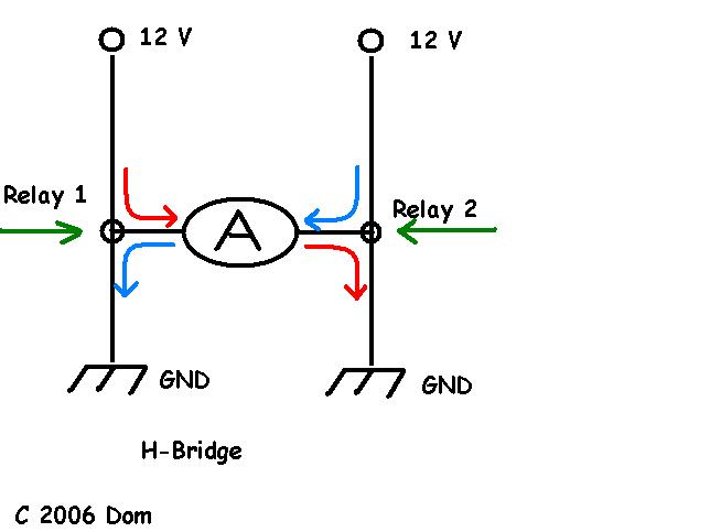
Another explanation on what is happening is that you are running an H-bridge circuit. The voltage to the actuator needs to be reversed so that it locks and unlocks. The way to do this is using a set of dual pole relays.
When the system is at rest they GROUND both sides of the actuator.
- the actuator does nothing
When relay 1 is activated the voltage follows the RED line through the actuator.
- the actuator locks
When relay 2 is activated the voltage follows the blue line through the actuator.
- the actuator unlocks
If the actuator is locking when it should be unlocking then it's wired backwards