
Converting FB Marker Lights To LED Lights

Thread Starter
Joined: Aug 2011
Posts: 3,078
Likes: 42
From: Cambridge, Minnesota
Hey guys, here is my build thread on how to make the halogen marker lights on an FB into LED marker lights.
Here is a picture of all 4 of my marker lights off of my FB. There are obviously 2 orange and 2 red marker lights on each side of the vehicle.

Here is a marker light with the colored filter covering it, the housing as it sits on the car.

A picture of a marker light with the bulb in it, cover removed.

This is the back of the marker light as it sits in the vehicle, wiring and all.

This is what the back of the marker light housing looks like after the wiring is removed (take out bulb first of course).

This is what the housing should look like after the bulb and wiring has been removed.

Here is a shot of what was taken out of all 4 of my marker lights (2 wires each housing and 1 bulb per housing x 4 = 8 wires and 4 bulbs removed).

Here is a picture showing how a marker light screws onto the car when left alone.

This is the corner of a marker light, you can see the gap between the housing and the colored cover.

If you have your trim still on your car then this is how you�d want to leave it.
I plan on removing my trim because it is starting to bow badly in the back by the gas cap (as everyone�s does) and I want it to look straighter and cleaner with better lines, I don�t like the blocky fading gray thick strip that takes away from my tornado gray colored car.
So this is an optional step, shaving the marker lights.
A. Press the housing firmly against the cover.
B. Take one of the screws that holds the marker lights together and use it to scratch around where the housing and the cover meet, scratching a line around the entire colored cover.
C. Take a Sharpie and color around the area to be shaved, everything on the housing (inside) side of the scratch you made � should look like the picture below

D. Use a file and file down everything that is Sharpie colored. This does not get everything that needs to be shaved to get the cover to fit flush against the housing, you will need to file the cover down much more than just the Sharpie colored portion (in my case at least). Don�t forget to do the sleeves where the screws go through or it won�t fit flatly against the housing!!

E. Check for fitment, the cover should fit flat and snug against the housing, having a much cleaner look.

Here is a picture of all 4 of my marker lights off of my FB. There are obviously 2 orange and 2 red marker lights on each side of the vehicle.
Here is a marker light with the colored filter covering it, the housing as it sits on the car.
A picture of a marker light with the bulb in it, cover removed.
This is the back of the marker light as it sits in the vehicle, wiring and all.
This is what the back of the marker light housing looks like after the wiring is removed (take out bulb first of course).
This is what the housing should look like after the bulb and wiring has been removed.
Here is a shot of what was taken out of all 4 of my marker lights (2 wires each housing and 1 bulb per housing x 4 = 8 wires and 4 bulbs removed).
Here is a picture showing how a marker light screws onto the car when left alone.
This is the corner of a marker light, you can see the gap between the housing and the colored cover.
If you have your trim still on your car then this is how you�d want to leave it.
I plan on removing my trim because it is starting to bow badly in the back by the gas cap (as everyone�s does) and I want it to look straighter and cleaner with better lines, I don�t like the blocky fading gray thick strip that takes away from my tornado gray colored car.
So this is an optional step, shaving the marker lights.
A. Press the housing firmly against the cover.
B. Take one of the screws that holds the marker lights together and use it to scratch around where the housing and the cover meet, scratching a line around the entire colored cover.
C. Take a Sharpie and color around the area to be shaved, everything on the housing (inside) side of the scratch you made � should look like the picture below
D. Use a file and file down everything that is Sharpie colored. This does not get everything that needs to be shaved to get the cover to fit flush against the housing, you will need to file the cover down much more than just the Sharpie colored portion (in my case at least). Don�t forget to do the sleeves where the screws go through or it won�t fit flatly against the housing!!
E. Check for fitment, the cover should fit flat and snug against the housing, having a much cleaner look.
Thread Starter
Joined: Aug 2011
Posts: 3,078
Likes: 42
From: Cambridge, Minnesota
Make sure you check your lights aren�t already shallow ones to begin with. One of my red marker lights was already trimmed down to the point where it fit flatly against the housing without any shaving. So I matched my other red one to it. But then both of my front orange/yellow ones looked ridiculously thick with the 1/4� or so of space separating the lip of the cover from the housing. So those got trimmed as well. I believe that this will look much better with none of that sun-fading, blocky, non-matching and graying trim I have all around.
My perfboard is painted, you can�t buy any like this that I know about. I got 2 sheets of 6� x 8�
perfboard from RadioShack for $7.25 and used a can of Rustoleum metallic spray paint to make the board look like that, it is a better custom look I think. I did check the paint after it dried with an Ohmmeter and it does not transfer a charge at all.
Here is the cut out of my perfboard for the marker lights. I checked fitment by holding the board up to the marker light housing and cutting out the appropriate section of perfboard.

This is what the board looks like inside of the light housing.

Here is the LED lighting order that I decided to put in my lights. I tried staggering them but decided that I didn�t like that look, and straight lines looks better on the FB in my opinion anyways (don�t worry, they won�t look Frankenstein-ish after I solder them and trim wires, that was just to make sure they work in the right order).

My soldering job on the first row of LEDs up next.

What the housing looks like with the LEDs mounted.

How the LED board sits inside the housing, not quite flush but the cover fits with space to spare.

What unlit LED board looks like inside the housing with the cover on.

This is why I mounted the LEDs in the less-diffused area of the housing. The first pic here is of the LED through the clearer area of the marker light.

This is what it looks like when an LED is mounted behind the really diffused area of the red cover, it isn�t nearly as bright and it doesn�t glow as well.

Here are a few pictures of the lights shining by themselves.


My perfboard is painted, you can�t buy any like this that I know about. I got 2 sheets of 6� x 8�
perfboard from RadioShack for $7.25 and used a can of Rustoleum metallic spray paint to make the board look like that, it is a better custom look I think. I did check the paint after it dried with an Ohmmeter and it does not transfer a charge at all.
Here is the cut out of my perfboard for the marker lights. I checked fitment by holding the board up to the marker light housing and cutting out the appropriate section of perfboard.
This is what the board looks like inside of the light housing.
Here is the LED lighting order that I decided to put in my lights. I tried staggering them but decided that I didn�t like that look, and straight lines looks better on the FB in my opinion anyways (don�t worry, they won�t look Frankenstein-ish after I solder them and trim wires, that was just to make sure they work in the right order).
My soldering job on the first row of LEDs up next.
What the housing looks like with the LEDs mounted.
How the LED board sits inside the housing, not quite flush but the cover fits with space to spare.
What unlit LED board looks like inside the housing with the cover on.
This is why I mounted the LEDs in the less-diffused area of the housing. The first pic here is of the LED through the clearer area of the marker light.
This is what it looks like when an LED is mounted behind the really diffused area of the red cover, it isn�t nearly as bright and it doesn�t glow as well.
Here are a few pictures of the lights shining by themselves.
Thread Starter
Joined: Aug 2011
Posts: 3,078
Likes: 42
From: Cambridge, Minnesota
Next up is a couple pictures of the lights shining through the housing.


Be warned, this is what a work bench can look like.

They are extremely bright, trust me on that. The ones I used here are 8,000 � 10,000 mcd for brightness. The very cheapest LEDs on eBay, came from China (I didn�t mean to get them from China; I just ordered the cheapest set of 50 with my eBay Bucks return). I will be buying U.S. LEDs for my tail lights from the eBay seller niktr0nix found here and get these LEDs found here (click on the word �here� in both those references to get to the places I�m referencing).
So, that�s about the end of that. It was a journey and I appreciated the lessons I learned throughout the build. I went into it with absolutely no LED experience and I now know enough to be dangerous with these little bright buggars. As some of you know, I plan on making LED tail lights as well. This was just a starting point, since I had to learn somehow, and I plan on making those as soon as possible. However, due to complexity and gradual learning, I will be doing my turn signals next since they require running lights and turning lights. I will post another write up on the forum here for everyone to enjoy and then I will tackle the tail lights after I know how I want to position the running/brake lights for it.
Thanks for sticking with it and showing an interest in the project, it means a lot. Thanks for looking and please PM me with any questions, comments, concerns. These are not for explicit sale, I do not wish to become an LED light dealer/builder. But if you are interested in a set you can PM me and we may be able to strike a deal. I am reasonable with pricing and will do honest work that both you and I can be proud of.
Thanks again guys,
Austin
Be warned, this is what a work bench can look like.
They are extremely bright, trust me on that. The ones I used here are 8,000 � 10,000 mcd for brightness. The very cheapest LEDs on eBay, came from China (I didn�t mean to get them from China; I just ordered the cheapest set of 50 with my eBay Bucks return). I will be buying U.S. LEDs for my tail lights from the eBay seller niktr0nix found here and get these LEDs found here (click on the word �here� in both those references to get to the places I�m referencing).
So, that�s about the end of that. It was a journey and I appreciated the lessons I learned throughout the build. I went into it with absolutely no LED experience and I now know enough to be dangerous with these little bright buggars. As some of you know, I plan on making LED tail lights as well. This was just a starting point, since I had to learn somehow, and I plan on making those as soon as possible. However, due to complexity and gradual learning, I will be doing my turn signals next since they require running lights and turning lights. I will post another write up on the forum here for everyone to enjoy and then I will tackle the tail lights after I know how I want to position the running/brake lights for it.
Thanks for sticking with it and showing an interest in the project, it means a lot. Thanks for looking and please PM me with any questions, comments, concerns. These are not for explicit sale, I do not wish to become an LED light dealer/builder. But if you are interested in a set you can PM me and we may be able to strike a deal. I am reasonable with pricing and will do honest work that both you and I can be proud of.
Thanks again guys,
Austin
When you plug them back into the harness, you may notice they flash faster than normally due to resistance I believe. Also, you may run in to some backfeeding of sorts which might keep the lights on slightly.
Let me know if you run in to that.
Let me know if you run in to that.

Trending Topics
His name is spot
Joined: Jul 2011
Posts: 244
Likes: 0
From: Western NC
Couple of questions - What is the value of the resistors you used? I was trying to decipher, but it's hard to see the colors in the pictures. I'm guessing 150 Ohm?? Also, have you measured the current draw versus the original? It would be interesting to know.
Nice write up!
Nice write up!
Thread Starter
Joined: Aug 2011
Posts: 3,078
Likes: 42
From: Cambridge, Minnesota
Couple of questions - What is the value of the resistors you used? I was trying to decipher, but it's hard to see the colors in the pictures. I'm guessing 150 Ohm?? Also, have you measured the current draw versus the original? It would be interesting to know.
Nice write up!
Nice write up!
I plan on working on the 7 today and I will try to put a set of these in and take pics so everybody can see what they look like installed. I will also try and get a shot of the original light in the 7, along with the LED installed. I'll also measure the output with my original 55 amp alternator and the 80 amp S4 alternator that I'm putting in - just to see if there's much of a difference. I will also try and include measures of the draw from the original halogen bulb setup and the LED setup.
love the braaaap
Joined: Jul 2003
Posts: 3,771
Likes: 5
From: Bognor, Ontario
This is a very interesting conversion that would have many benefits on a 1st gen, besides having brighter lights. Converting to LED's in place of all the original incandescent bulbs will greatly reduce the current draw on the electrical system which is always a plus since the original wiring does not use relays in most cases and to be honest, the orignal wiring is somewhat substandard IMO.
There are a few things to consider when doing this though, and for the most part others have somewhat quietly mentioned. One is the resistance difference from regular bulbs. The LED units will have a higher resistance from the original bulb, and in the case of turn signals, the flasher unit relies on low resistance to work properly. Your average incandescent bulb has a resistance of about 5 ohms, not 150. Signals will flash too quickly if this low resistance is not maintained, as if one of your bulbs is burnt out. Correct me if I'm wrong, but a resistor of about 5-10 ohms across the + and - terminals will show to the flasher unit that a regular bulb is in place. FYI, this also comes into play on the tail/brake lights in that the dash light indicating a burnt out taillight bulb will come on when using LED's.
Another problem that may be encountered is backfeeding and power spikes to the LED units. This can quickly fry the LED's and a diode should be used to suppress that. As with the resistor mentioned above, the diode would be placed between + and - to bleed off any backfeeding on the negative circuit.


Are you going to drive two sets of LEDs for brake and tail lights or just very the voltage for all of them? A circuit like this might help.
http://www.redcircuits.com/Page85.htm
http://www.redcircuits.com/Page85.htm
A lit incandescent bulb has more resistance than not lit. It is always best to measure a lit bulb for resistance values, especially when the flasher works off of that resistance and not the unlit.
Thread Starter
Joined: Aug 2011
Posts: 3,078
Likes: 42
From: Cambridge, Minnesota
This is a very interesting conversion that would have many benefits on a 1st gen, besides having brighter lights. Converting to LED's in place of all the original incandescent bulbs will greatly reduce the current draw on the electrical system which is always a plus since the original wiring does not use relays in most cases and to be honest, the orignal wiring is somewhat substandard IMO.
There are a few things to consider when doing this though, and for the most part others have somewhat quietly mentioned. One is the resistance difference from regular bulbs. The LED units will have a higher resistance from the original bulb, and in the case of turn signals, the flasher unit relies on low resistance to work properly. Your average incandescent bulb has a resistance of about 5 ohms, not 150. Signals will flash too quickly if this low resistance is not maintained, as if one of your bulbs is burnt out. Correct me if I'm wrong, but a resistor of about 5-10 ohms across the + and - terminals will show to the flasher unit that a regular bulb is in place. FYI, this also comes into play on the tail/brake lights in that the dash light indicating a burnt out taillight bulb will come on when using LED's.
Another problem that may be encountered is backfeeding and power spikes to the LED units. This can quickly fry the LED's and a diode should be used to suppress that. As with the resistor mentioned above, the diode would be placed between + and - to bleed off any backfeeding on the negative circuit.
There are a few things to consider when doing this though, and for the most part others have somewhat quietly mentioned. One is the resistance difference from regular bulbs. The LED units will have a higher resistance from the original bulb, and in the case of turn signals, the flasher unit relies on low resistance to work properly. Your average incandescent bulb has a resistance of about 5 ohms, not 150. Signals will flash too quickly if this low resistance is not maintained, as if one of your bulbs is burnt out. Correct me if I'm wrong, but a resistor of about 5-10 ohms across the + and - terminals will show to the flasher unit that a regular bulb is in place. FYI, this also comes into play on the tail/brake lights in that the dash light indicating a burnt out taillight bulb will come on when using LED's.
Another problem that may be encountered is backfeeding and power spikes to the LED units. This can quickly fry the LED's and a diode should be used to suppress that. As with the resistor mentioned above, the diode would be placed between + and - to bleed off any backfeeding on the negative circuit.
These will be between the + and - terminals for the turn signals up front and the turn signals and brake lights in back.
I really need some help with wiring this diode in though, here comes REPU...
Are you going to drive two sets of LEDs for brake and tail lights or just very the voltage for all of them? A circuit like this might help.
http://www.redcircuits.com/Page85.htm
http://www.redcircuits.com/Page85.htm
Here's an excerpt from my post about tail light building found HERE
So let�s discuss this. There are 3 wires that run to each of the turn signals up front, and 3 wires that run to the tail/brake lights in the back. Here�s a crazy test I decided to do, and it has really confused me as to the function of these 3 wires. I know the Black wires are a ground, which is clear on the FSM.
Front Turn Signals Original Wiring
(Left+Right)Black = Ground
(Left+Right)Red/Green = Running Light Power in 8W bulb filament
(Right)Green/Orange and (Left)Green/Red = Turn Signal Power in 27W bulb filament
If I all 3 of the Black, Green/Orange and Red/Green wires are connected in the left front blinker assembly, the unit functions as it should and has a running light and a bright turn signal. Following is a test of the different wire combinations and what they do to the car and the bulb, quite interesting to study. It was done with the turn signal on, because that is where I knew I would have the issue.
Blk + Gr/Or + Red/Gr = Bright turn signal, regular blinking
Blk + Gr/Or = Bright turn signal, regular blinking
Blk + Red/Gr = Bright solid light with no blinking in front, fast blink in the back like the front bulb is burnt out.
Red/Gr + Gr/Or = Weak turn signal in front, fast blink in the back like the front bulb is burnt out.
Should be correct, after doing extensive homework with the wiring diagram I believe that I have the concept right. So the wiring on the front turn signals will be as follows:
Black + Red/Green will be the combo for one row of LEDs that serve as my running lights.
Black + Green/Orange will be the combo for 2 rows of LEDs that serve as my turn signals.
I will leave them all plugged in for when they are operational so that I do not have to do anything silly. I will probably arrange the LEDs in this fashion so that the middle is running lights and the top and bottom rows will be blinking turning signal lights:
(o)(o)(o)Turning(o)(o)(o)
(o)(o)(o)Running(o)(o)(o)
(o)(o)(o)Turning(o)(o)(o)
==================================================
Let me know your guys' ideas with how to build these with differing brightness/voltage incorporating a diode and resistors.
While I think the 6 LED marker lights look much better, for those who want an easier conversion to LED's, you can order LED bulbs that plug right in, replacing just about every bulb in the car, including dash/cluster. I've already swapped out nearly everything. Colored ones as well.
http://www.superbrightleds.com/cgi-b...sp=%2F1157.htm
I've already swapped out nearly everything. Colored ones as well.
http://www.superbrightleds.com/cgi-b...sp=%2F1157.htm
http://www.superbrightleds.com/cgi-b...sp=%2F1157.htm

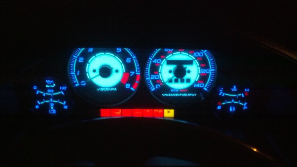
okay so gauge faces are reverse glow, needles WILL be glowing as well as soon as I get around to installing them. All bulbs switched to led. Also pics of dome/map lights and video of taillights in action.
http://s1239.photobucket.com/albums/...-14-05_561.mp4
http://s1239.photobucket.com/albums/...-14-05_561.mp4
Full Member
Joined: Nov 2011
Posts: 242
Likes: 1
From: Sacramento
That dash is awesome
That dash is awesome. How did you do it, is it a kit or did you do it all yourself?

Installing the reverse glow faces was easy, remove the cluster and it slips right on top of the old faces. With the bulbs I literally just unplugged every bulb I was going to change out and took the numbers off them. The site ( http://www.superbrightleds.com/cgi-b...nstrument.html ) says beside each bulb they sell what it replaces. The ones on the gauge cluster were a tight fit, but they did work. I did not write down any part numbers, just went by pics and numbers on the old bulbs.
Where did you get the "reverse glow faces" and what are they? What do they look like in daylight?
Installing the reverse glow faces was easy, remove the cluster and it slips right on top of the old faces. With the bulbs I literally just unplugged every bulb I was going to change out and took the numbers off them. The site ( http://www.superbrightleds.com/cgi-b...nstrument.html ) says beside each bulb they sell what it replaces. The ones on the gauge cluster were a tight fit, but they did work. I did not write down any part numbers, just went by pics and numbers on the old bulbs.