(INTAKE) Megasquirt in FB?

Full Member
Joined: Oct 2003
Posts: 118
Likes: 0
From: Bellingham washington
I'm in the process of doing one now. I intend to use a GM tbi and sensors. I'll have parameters in a month or so. In the mean time this link has some great info and parameters for a 13b
http://www.megamanual.com/v22manual/rotary.htm
http://www.megamanual.com/v22manual/rotary.htm
I built an MS in '04 and spent a while installing it in my GLC in early '05. I removed it in '06 and it sits until I can install it in my 1st gen. So in other words, I'm not of very much help right now. I'll probably come to you with questions when I'm ready to install mine. 
Thread Starter
i play with my wankel
Joined: Jul 2005
Posts: 1,630
Likes: 0
From: North Manchester, Indiana
haha thx bud and jeff i have mine built it only took me about 3 hours tops and my harness is done i just need to wire it and tune....fun. o jeff are you using stock FB ignition? i was told using a 2nd gen CAS would be easier..thx again bud
I used a CAS and found a signal conditioner that worked. The ignitors and coils are stock FB because it's what I had at the time. If I had it to do over again, I'd consider 2nd gen ignitors and coils. The 1st gen stuff did work though. I didn't experience any ignition break up.
Trending Topics
Thread Starter
i play with my wankel
Joined: Jul 2005
Posts: 1,630
Likes: 0
From: North Manchester, Indiana
Here is an example of a full rotary set-up:
* Car: 1985 Mazda RX-7 GSL-SE
* Motor: Stock 13B, 2�720cc/min Mazda Injectors
* Current MegaSquirt Parameters:
o REQ_FUEL: 8.0
o INJ Open: 1.0
o PWM Current: 75%
o PWM Time: 2.5
+ 1 squirt,
+ Simultaneous,
+ 4 stroke,
+ 4 cyl,
+ MPI,
+ 2x inj,
+ 250kPa
+ Baro,
+ Even fire
* Car: 1985 Mazda RX-7 GSL-SE
* Motor: Stock 13B, 2�720cc/min Mazda Injectors
* Current MegaSquirt Parameters:
o REQ_FUEL: 8.0
o INJ Open: 1.0
o PWM Current: 75%
o PWM Time: 2.5
+ 1 squirt,
+ Simultaneous,
+ 4 stroke,
+ 4 cyl,
+ MPI,
+ 2x inj,
+ 250kPa
+ Baro,
+ Even fire


Rotary Enthusiast
Joined: Oct 2001
Posts: 1,022
Likes: 4
From: Ontario, Canada
For GSL-SE, you must fire the two injectors together in simultaneous mode. You could wire them one each to the two MS injector outputs, but I'd set them both on one bank, and leave the second output open.
Full Member
Joined: Oct 2003
Posts: 118
Likes: 0
From: Bellingham washington
Like I say I'm just learning the system, I was refering to the section on "kurt staging" in the link I posted at the begining of the thread. It sounds like Renns has some experiance with this and I don't -yet-
Rotary Enthusiast
Joined: Oct 2001
Posts: 1,022
Likes: 4
From: Ontario, Canada
The 'Kurt Staging' scheme is based on using primary and secondary injectors of equal sizes. All injectors operate throughout the full rpm/load range, but are fired in alternating mode. This is a relatively obscure method of operation that doesn't normally lend itself to rotary applications, as the rotary throttle body has a primary butterfly that opens before the secondary ones. With progressive TB's like this it's preferred to inject fuel into the primary runner only until the secondary butterflies have opened enough to properly carry the fuel into the engine. That's why a proper method of staged injection was developed and added to the msnsextra version of embedded code.
Attached is typical wiring diagram. Build a custom harness, and splice into the stock wiring where needed. In my install I included a custom mount for FC fuse block, and an array of 4 relays (fuel pump, ignition, e-fan high/low) as well.
Note that pins 25, 27, 29, 31, and 36 are not used in a std MS build, so they can be assigned to whatever inputs or outputs you desire. I used three of them for ignition outputs, one for electric fan control, and the last for fuel pressure signal input.
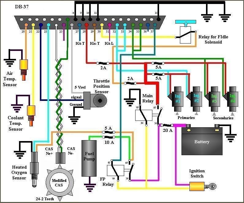
Rotary Enthusiast
Joined: Oct 2001
Posts: 1,022
Likes: 4
From: Ontario, Canada
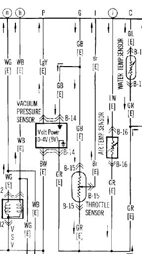
The TPS is shown as a resistor symbol. The signal wire is the one shown coming out the side of the resistor. It's wire will also have an small arrow pointing towards the ecu. The +ve side of the TPS is connected directly to the ecu, with an arrow pointing from ecu to TPS.