
Power FC Fuel Temp Highlighted 4.98 Volts


Thread Starter
Hooray For Boobies!!!
Joined: Sep 2002
Posts: 3,570
Likes: 1
From: Washington
Fuel Temp Highlighted 4.98 Volts
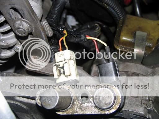
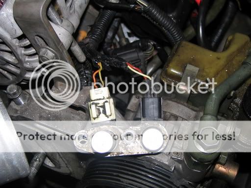
I have just finished with a motor install and I am running into problems. One of them is the fuel temp sensor is highlighted and reading 4.98 volts on the commander. I have searched and first thought great I just reversed/swapped the two green connectors. Well that wasn't true, they are in the correct locations. I have looked them up and matched wire colors. I have also looked at some of my engine bay pics prior to the new engine and the connector and wires match.
So I have the correct connector on the sensor. The sensor was working prior to the broken apex seal (dead motor).
I am now looking up the pin outs on the ECU and looking for the fuel temp wire going into the ECU, but I am having trouble locating it. Maybe it is shorting out somewhere?
What would cause the sensor to be highlighted and reading 4.98 volts even when the connector is removed from the fuel temp sensor at the engine bay?
Could this cause a rich condition (probably), because the car is flooded now?
ps here is my sig. I have made the street ports larger, port matched everything and added a SX FPR, which may be part of my flooding problem.
Thanks
Joe
Thread Starter
Hooray For Boobies!!!
Joined: Sep 2002
Posts: 3,570
Likes: 1
From: Washington
Found the wire going to the ECU. It is going to ECU connector B1-01 pin D1 wire color W/R. This is the 11 x 2 (22 pin) connector.
I guess when I get home I will start ohming through this and also disconnect it at the ECU to see if the sensor unhighlights.
Just looking for feedback and ideas.
Thanks
I guess when I get home I will start ohming through this and also disconnect it at the ECU to see if the sensor unhighlights.
Just looking for feedback and ideas.
Thanks
Of course you know that both the water and fuel temp sensor beside having the same type and color connector, are also the same sensor. The only difference is one uses a crush washer and the other uses an "O" ring seal.
What can you learn if you swap connectors on purpose, and compare PFC readings before and after?
What can you learn if you swap connectors on purpose, and compare PFC readings before and after?


If it's getting almost 5 volts, either the sensor is open circuit or the 5v supply has shorted into the signal line. Try unplugging the sensor and checking the PFC - if it still reads almost 5v, you've got a short somewhere.
Dale
Dale
Thread Starter
Hooray For Boobies!!!
Joined: Sep 2002
Posts: 3,570
Likes: 1
From: Washington
Originally Posted by cewrx7r1
Of course you know that both the water and fuel temp sensor beside having the same type and color connector, are also the same sensor. The only difference is one uses a crush washer and the other uses an "O" ring seal.
Originally Posted by cewrx7r1
What can you learn if you swap connectors on purpose, and compare PFC readings before and after?
Originally Posted by DaleClark
If it's getting almost 5 volts, either the sensor is open circuit or the 5v supply has shorted into the signal line. Try unplugging the sensor and checking the PFC - if it still reads almost 5v, you've got a short somewhere.
Dale
Dale
I think the PFC will read high voltage on the sensor when it is disconnected or open. I found that the wire for the fuel temp sensor was already cut and taped back together from a previous owner. I untapped the splice job and it was obvious why it was not getting a signal.
Originally Posted by 93FD3S
I thought you can run the PFC with fuel temp sensor unconnected without any negative effects......?
Thanks Guys!
Last edited by x605p747R1; Jan 12, 2005 at 11:24 AM.
Big Snail
Joined: Dec 2001
Posts: 1,230
Likes: 3
From: San Antonio
So what are the color of the wires for the water temp plug I'm actually wondering if I have them reversed with the fuel temp plug. I hope not because I cut off the fuel temp plug, thats gonna really suck if I have to check every wire.
Trending Topics
Thread Starter
Hooray For Boobies!!!
Joined: Sep 2002
Posts: 3,570
Likes: 1
From: Washington
In section Z (wiring diagram) of the FSM on page 30 you will find the Fuel Thermosensor (BR/B and BR/Y). This is going to the 22 pin connector on the ECU via 1D of that connector (W/R)
On page 32 you will find the Water Thermosensor (BR/B and G/W). This is going to 16 pin connector on the ECU via 3E of that connector (G/W)
Not sure what the connector names are so I listed them by the number of pins on that connector. The 22 pin connector is an 11 x 2 and the 16 pin connector is an 8 x 2 connector.
Hope this helps.
Thread Starter
Hooray For Boobies!!!
Joined: Sep 2002
Posts: 3,570
Likes: 1
From: Washington
Don't listen to my 2nd to last post or hell even the last one 
But anyways after taking a better look at he FSM and seeing that I was incorrect. I felt I should tell you.
The two wires coming off the green fuel thermo sensor are Brown with a Black stripe and Brown with a Yellow strip. The Brown Yellow wire goes to the ECU pin 1U. This is B1-01 connector (11 x 2 pin yellow ECU harness) on the outside edge of the connector. Check for continuity between the ECU harness and the correlating wire on the fuel temp sensor. The Brown Black wire goes to (pg Z-32) and ties into the Intake air temp sensor, the Water thermo sensor, the pressure sensor, EGR switch (if equip), Throttle sensor and the �ring pump� (manual has been copied and this lands right on the bind). But from the Brown Black wire to pin 4D on B1-01 ECU harness should be connected. From there you should check all your sensors and their connections to the ECU.
I am still working on this for my car but I felt I should to correct myself after taking a better look and realizing I made a mistake. I hope this helps a little bit more. I post my results later.
Sorry.
Thread Starter
Hooray For Boobies!!!
Joined: Sep 2002
Posts: 3,570
Likes: 1
From: Washington
Originally Posted by x605p747R1
Don't listen to my 2nd to last post or hell even the last one
But anyways after taking a better look at he FSM and seeing that I was incorrect. I felt I should tell you.
The two wires coming off the green fuel thermo sensor are Brown with a Black stripe and Brown with a Yellow strip. The Brown Yellow wire goes to the ECU pin 1U. This is B1-01 connector (11 x 2 pin yellow ECU harness) on the outside edge of the connector. Check for continuity between the ECU harness and the correlating wire on the fuel temp sensor.
Originally Posted by x605p747R1
The Brown Black wire goes to (pg Z-32) and ties into the Intake air temp sensor, the Water thermo sensor, the pressure sensor, EGR switch (if equip), Throttle sensor and the �ring pump� (manual has been copied and this lands right on the bind). But from the Brown Black wire to pin 4D on B1-01 ECU harness should be connected. From there you should check all your sensors and their connections to the ECU.
I am still working on this for my car but I felt I should to correct myself after taking a better look and realizing I made a mistake. I hope this helps a little bit more. I post my results later.
Sorry.
I am still working on this for my car but I felt I should to correct myself after taking a better look and realizing I made a mistake. I hope this helps a little bit more. I post my results later.
Sorry.
And the ring pump thing is the oil metering pump.
Sorry for all the confusion.
Thread Starter
Hooray For Boobies!!!
Joined: Sep 2002
Posts: 3,570
Likes: 1
From: Washington
Originally Posted by rotoboy661
its your CAS man not connected
mine did that too
check that 1st
-mike
mine did that too
check that 1st
-mike
The fuel temp sensor has nothing to do with it. I just noticed it was highlighted and reading 4.98 volts, when prior to the new engine this was not highlighted. So I thought I would track that down while I am waiting on "new" used CAS connectors.
Thanks
Big Snail
Joined: Dec 2001
Posts: 1,230
Likes: 3
From: San Antonio
ahhh...thanks for the clarification. Yeah the little clip that you squeeze to remove the plug for the right sensor connector broke off. Seems pretty secure without the little tab, hope it doesn't come loose while on a hard run. could be bad news I imagine.
you may wantto check the connector from the engine harness to the dash harness. I had a problem with that connectors pins not lineing up and it caused all kinds of funky issues. one of which was a check engine code for the fuel temp sensor. Fixed the pins and the problems all disappeared.
just spomething to check maybe.
If i remember rite neither side of the fuel temp circuit would test properly. power or ground side.
just spomething to check maybe.
If i remember rite neither side of the fuel temp circuit would test properly. power or ground side.

Thread
Thread Starter
Forum
Replies
Last Post
Skeese
Adaptronic Engine Mgmt - AUS
65
Mar 28, 2017 03:30 PM
immanuel__7
2nd Generation Specific (1986-1992)
89
Sep 5, 2015 10:23 AM