Microtech FD CAS Wiring
 01-08-14, 10:58 PM
#1
Hello members,
I have a problem which I`m trying to solve but just ending up at a road block. Hopefully you can give me some pointers.
I have a series 6 (FD) street ported motor with an LT8s ECU. I have installed the CAS as described in the manual provided when purchased. However, after losing compression due to excessive internal heat (flat corner seals); I contacted Jon at Microtech regarding my CAS wiring issue. To my surprise, Microtech has now posted a correction to the CAS wiring which is now posted on their website.
I`ve now rebuilt the motor and rewired the CAS sensor as described by Microtech. However, when I check the timing the trailing is dead on the money (20 ATDC), but the Leading which I know should be 5 ATDC; is now showing me 65 ATDC.
Things I’ve check thus far:
1. Pulleys which can only install in one way
2. Tested both sensors which both read 1.1 ohm
3. Check both CAS connectors, both are ok.
4. When installed the way as described in the install manual the timing is still the same.
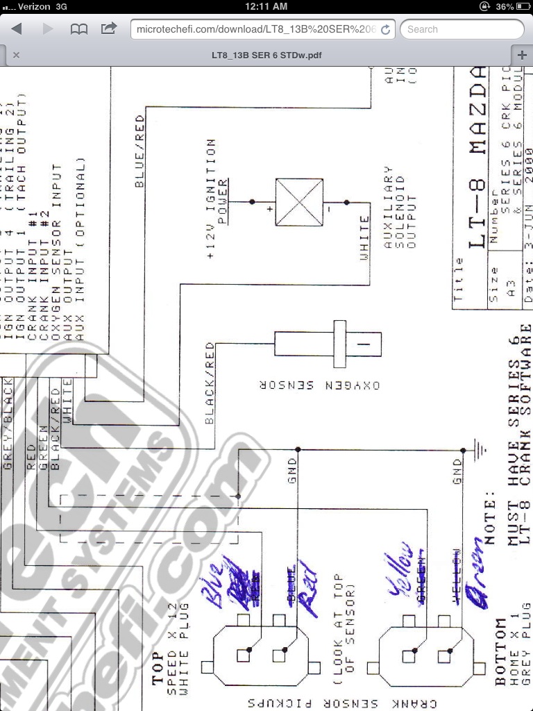
Car starts and runs either way but I just want to rectify this problem. Also, original install diagram within the manual shows different ground points as compared to the now revised diagram posted online. Also the wires have been switched around as well... as seen in the link provided.
See picture: Note the diagram in the manual shows the ground points (similar to the OEM ground points) on the other end of the connector other than what is pictured below.
Any insight would be greatly appreciated.
Thanks,
Andre
I have a problem which I`m trying to solve but just ending up at a road block. Hopefully you can give me some pointers.
I have a series 6 (FD) street ported motor with an LT8s ECU. I have installed the CAS as described in the manual provided when purchased. However, after losing compression due to excessive internal heat (flat corner seals); I contacted Jon at Microtech regarding my CAS wiring issue. To my surprise, Microtech has now posted a correction to the CAS wiring which is now posted on their website.
I`ve now rebuilt the motor and rewired the CAS sensor as described by Microtech. However, when I check the timing the trailing is dead on the money (20 ATDC), but the Leading which I know should be 5 ATDC; is now showing me 65 ATDC.
Things I’ve check thus far:
1. Pulleys which can only install in one way
2. Tested both sensors which both read 1.1 ohm
3. Check both CAS connectors, both are ok.
4. When installed the way as described in the install manual the timing is still the same.
Car starts and runs either way but I just want to rectify this problem. Also, original install diagram within the manual shows different ground points as compared to the now revised diagram posted online. Also the wires have been switched around as well... as seen in the link provided.
See picture: Note the diagram in the manual shows the ground points (similar to the OEM ground points) on the other end of the connector other than what is pictured below.

Any insight would be greatly appreciated.
Thanks,
Andre

 01-22-14, 07:26 AM
#4
No, microtech said the ignition fires in waste spark. Therefore, I had to remark the pulley 180 degrees for T2 and remark 15 degrees advanced from stock ignition point T1.
Once it did that and rechecked the timing it was on the money.
I also asked microtech about the revision to the wiring diagram on their website, and they said that revision was for the later batch of ECUs manufactured.
Andre
Once it did that and rechecked the timing it was on the money.
I also asked microtech about the revision to the wiring diagram on their website, and they said that revision was for the later batch of ECUs manufactured.
Andre

Thread
Thread Starter
Forum
Replies
Last Post
toplessFC3Sman
2nd Generation Specific (1986-1992)
6
03-20-18 01:54 PM