
Mississippi FD - 383CI Forged LS1 Stroker Build

Thread Starter
Joined: Apr 2009
Posts: 381
Likes: 27
From: Starkville, MS
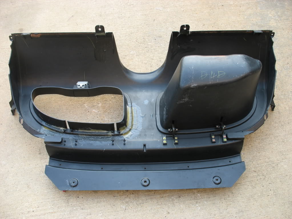
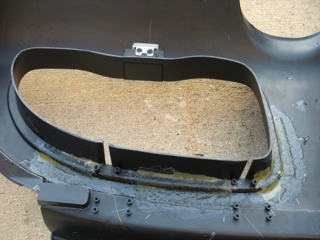
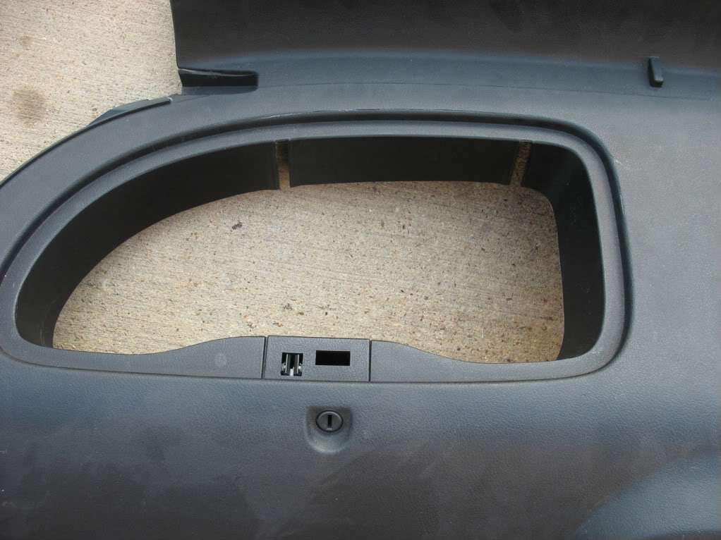
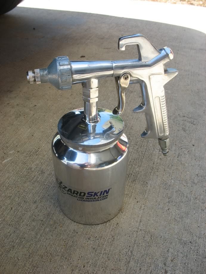
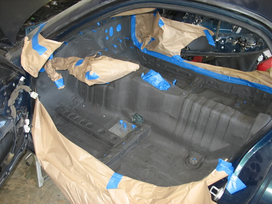
Finally finished scraping out the stock soundproofing and masking for the lizard skin.
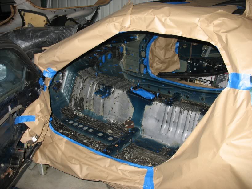
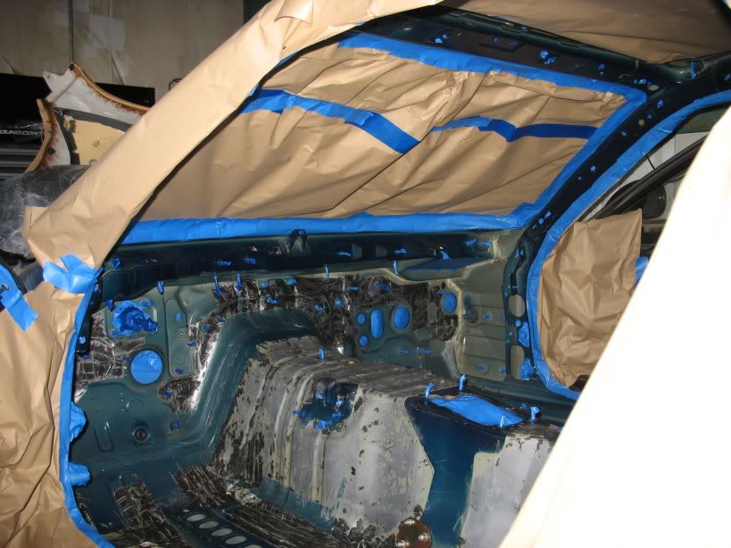
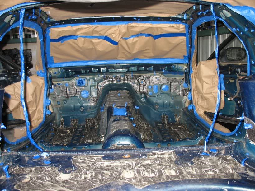
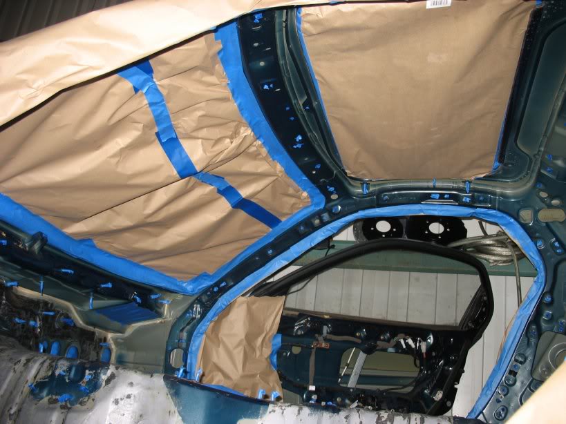
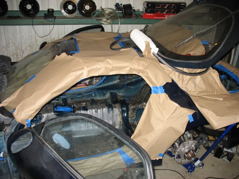
As you can see... I pretty much stripped every square inch of my interior. It was a PITA but I figure if I'm going to do it
once I might as well do it right
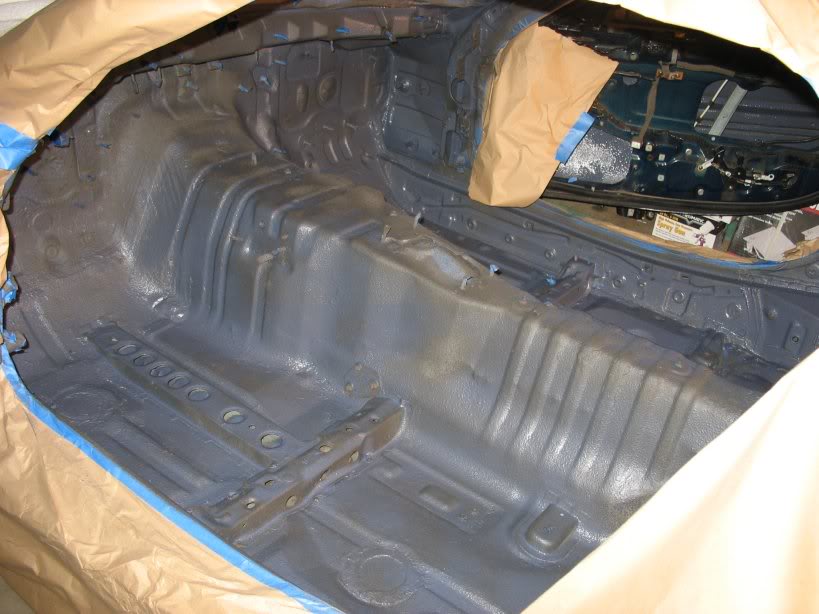
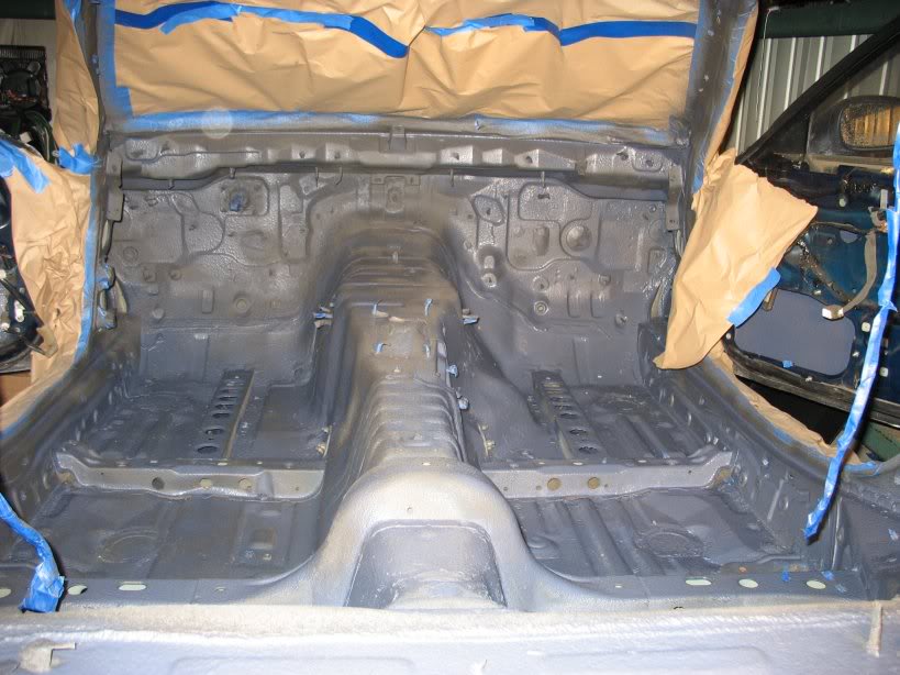
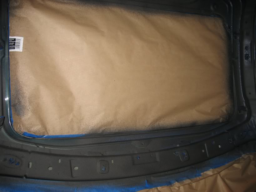
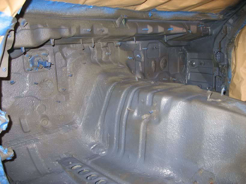
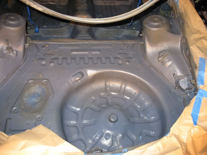
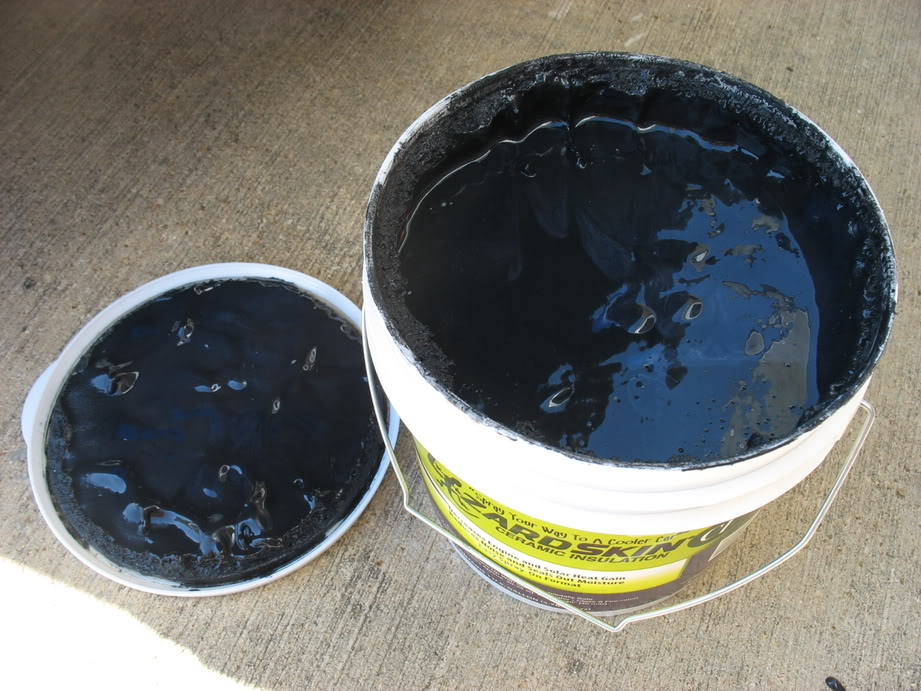
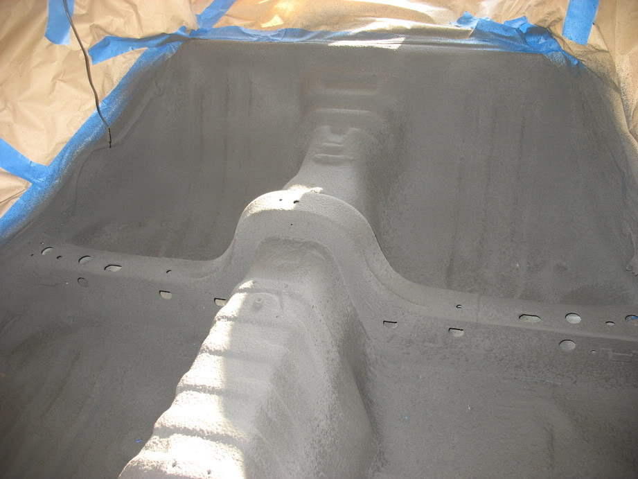
That only took the better part of two gallons. I've got 2 more so I'm going to do another coat next weekend.
As you can see... I pretty much stripped every square inch of my interior. It was a PITA but I figure if I'm going to do it
once I might as well do it right
That only took the better part of two gallons. I've got 2 more so I'm going to do another coat next weekend.

Thread Starter
Joined: Apr 2009
Posts: 381
Likes: 27
From: Starkville, MS
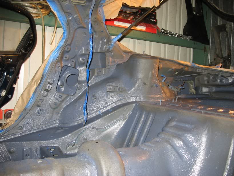
I thought I'd have to paint the inside skins of my doors with a brush/roller, but I managed to do it with my spray gun using
the 3 access holes I could get a nozzle through. After looking inside with a flashlight I confirmed I got everything inside
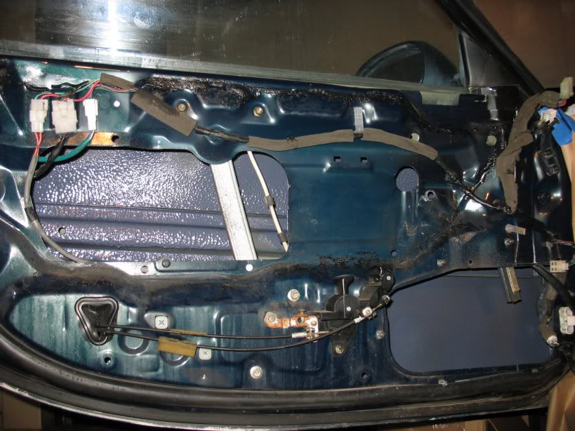
Oh yeah, just for kicks and giggles, here's the mats my brothers got me for my birthday last month:
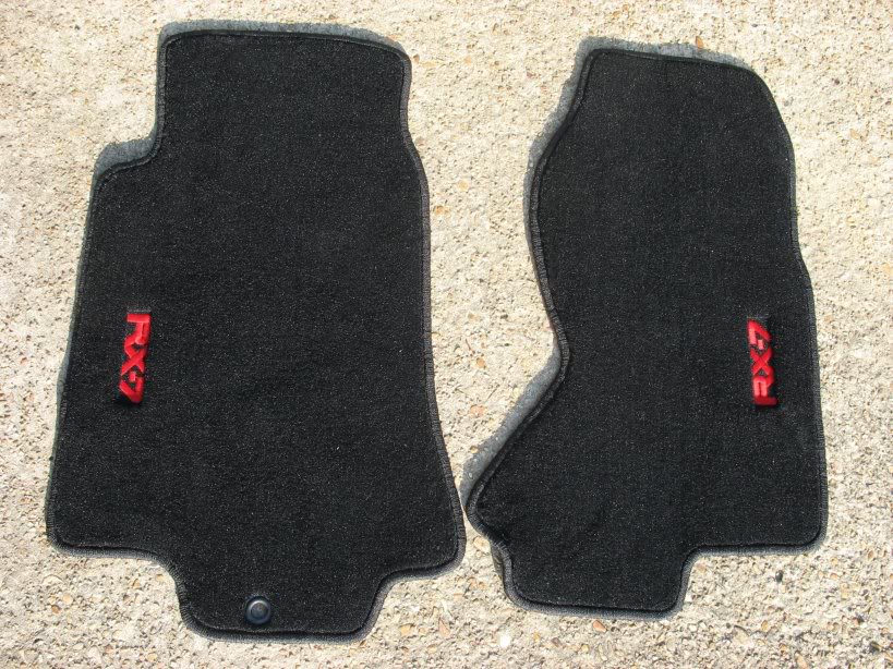
Lane
the 3 access holes I could get a nozzle through. After looking inside with a flashlight I confirmed I got everything inside
Oh yeah, just for kicks and giggles, here's the mats my brothers got me for my birthday last month:
Lane
damn i miss my punched out 383 stroker elcamino... it was that car or the 7, of course i wouldn't be here if it was a question as to which i still have. plenty of torque to push the car sideways at any shift at any speed. and that thing was a boat!
Thread Starter
Joined: Apr 2009
Posts: 381
Likes: 27
From: Starkville, MS
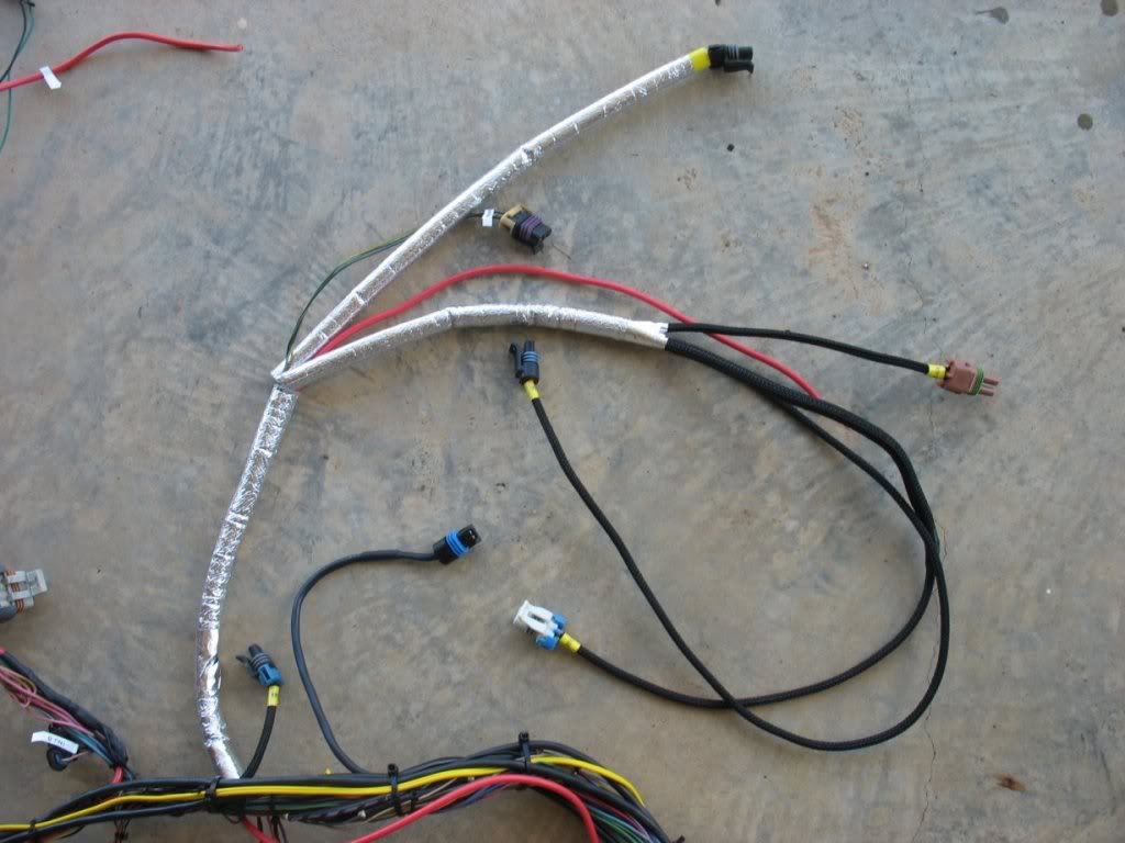
Managed to shoot another coat of lizard skin on Monday and let it dry all week. Spent my Saturday stripping all the masking
out of my car from the lizard skin and reinstalling my fenders and front bumper support. Today I worked on my fuel system.
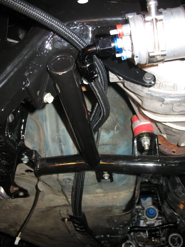
I was hoping it would be a cleaner install, but I had to involve some heat-shielding sleeves on my fuel lines since they ran
within a few inches of my headers on the way back to the gas tank.
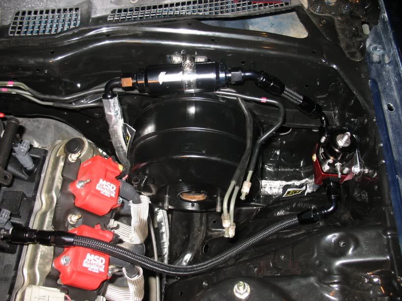
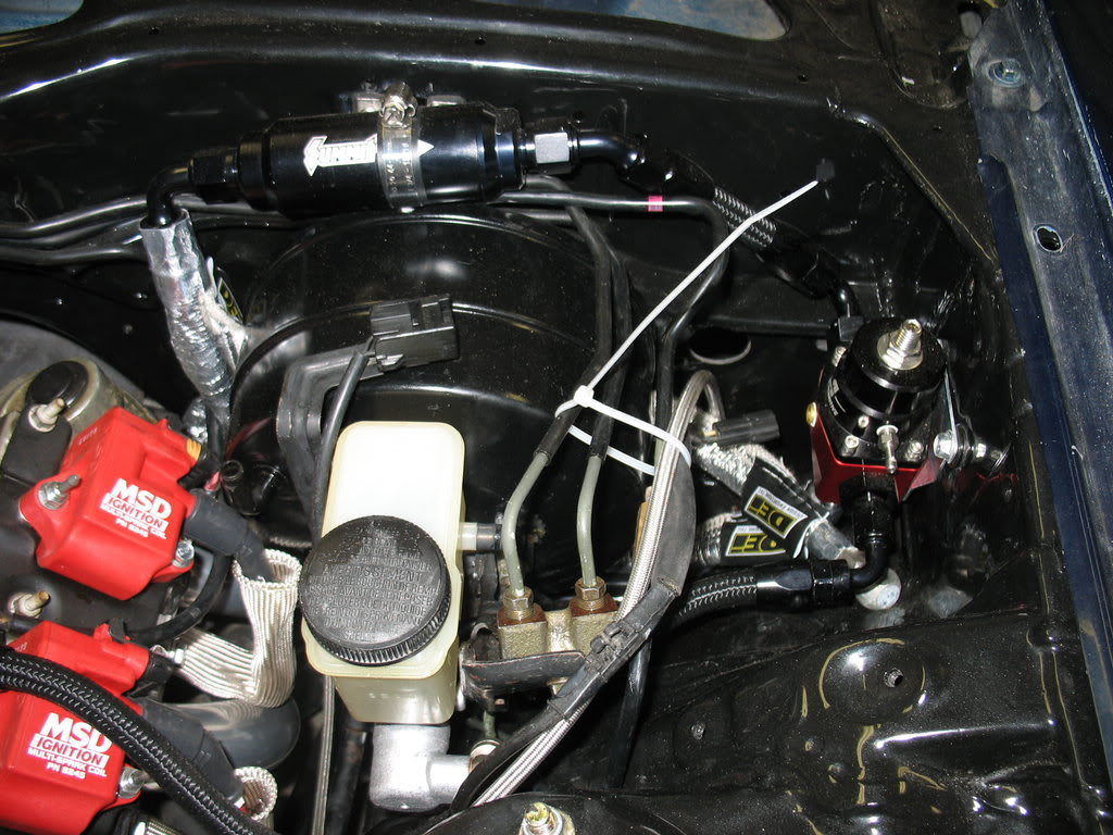
The input line comes up from the passenger side of the brake booster to the 10um filter on top of the brake booster / master
cylinder.
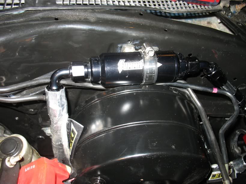
10um filter and 8AN fuel line with a DEI heat sleeve.
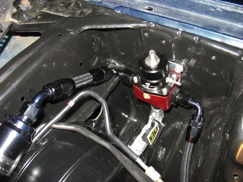
Aeromotive regulator. 8AN Input on left, 6AN output on right, 6AN return line out the bottom.
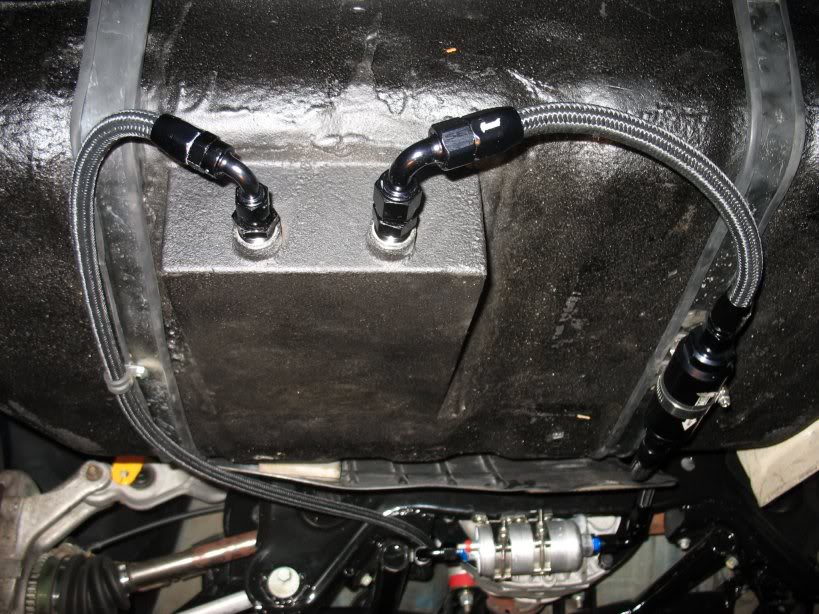
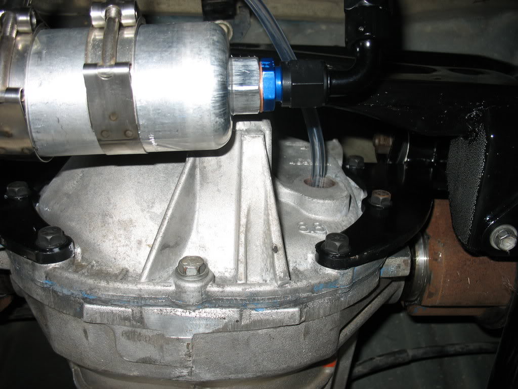
Sumped fuel tank from the rear of the car. The passenger side port feeds the 8AN line which is then pre-filtered to 100um
before it hits the fuel pump. The drivers side port is the fuel return line that runs straight to the regulator.
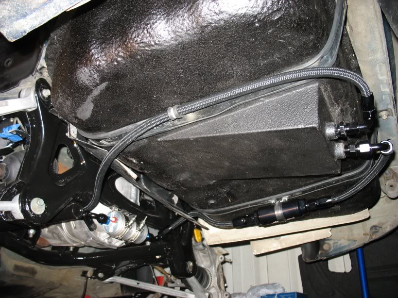
Drivers side view from under the car
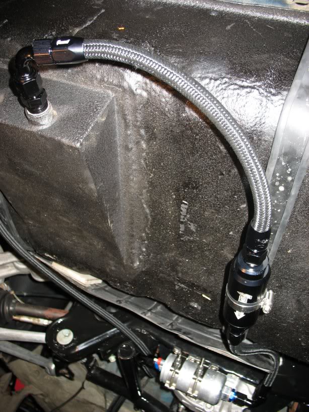
100um filter
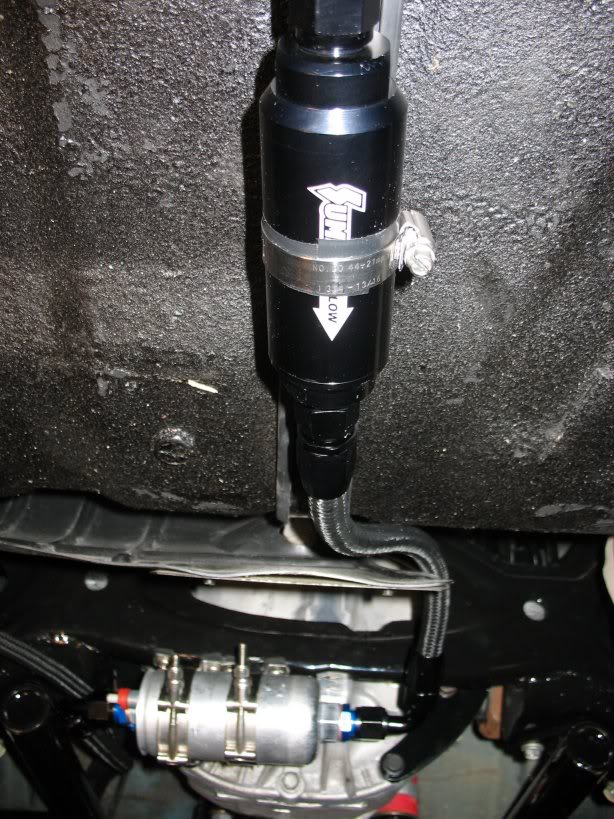
100um filter to fuel Bosch 044 fuel pump
A bad picture of the routing from the fuel pump to the front of the car. You can also see the fuel return line running to
the front of the car as well.
Lane
out of my car from the lizard skin and reinstalling my fenders and front bumper support. Today I worked on my fuel system.
I was hoping it would be a cleaner install, but I had to involve some heat-shielding sleeves on my fuel lines since they ran
within a few inches of my headers on the way back to the gas tank.
The input line comes up from the passenger side of the brake booster to the 10um filter on top of the brake booster / master
cylinder.
10um filter and 8AN fuel line with a DEI heat sleeve.
Aeromotive regulator. 8AN Input on left, 6AN output on right, 6AN return line out the bottom.
Sumped fuel tank from the rear of the car. The passenger side port feeds the 8AN line which is then pre-filtered to 100um
before it hits the fuel pump. The drivers side port is the fuel return line that runs straight to the regulator.
Drivers side view from under the car
100um filter
100um filter to fuel Bosch 044 fuel pump
A bad picture of the routing from the fuel pump to the front of the car. You can also see the fuel return line running to
the front of the car as well.
Lane
Thread Starter
Joined: Apr 2009
Posts: 381
Likes: 27
From: Starkville, MS
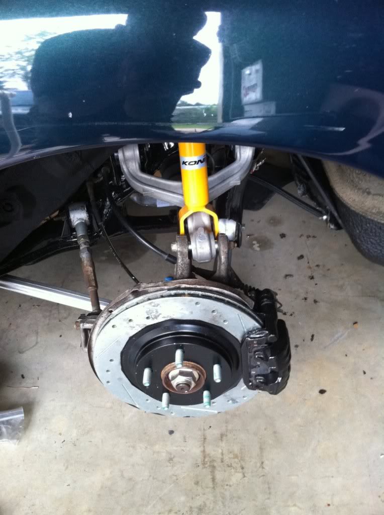
Not much happened this weekend. It was all about brakes, brackets, and cleaning.
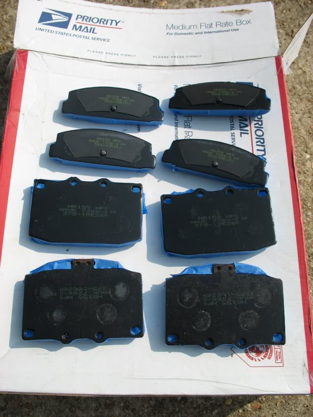
Hawk HP pads masked for anti squeal coating,
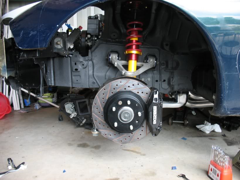
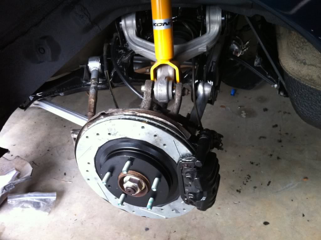
Front brakes installed
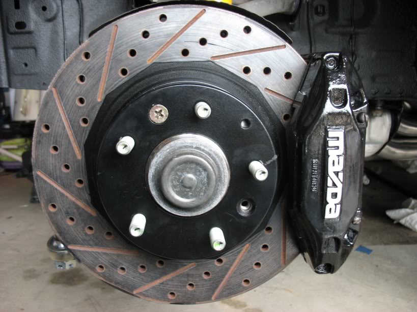
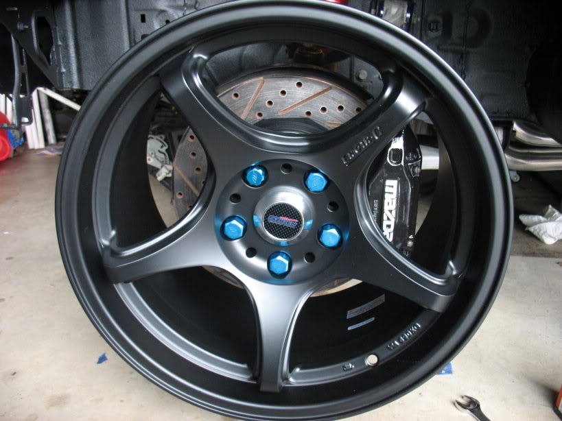
Another shot. I finally got around to sanding the mazda logo. I really like it since it takes the focus off of my shitty
paint job
The front brake install is about 90% done. I spent an hour trying to figure out how the front hard-lines connected to the
brake MC and ABS unit respectively, until I remembered that the car came without ABS and after looking at some older
pictures I discovered that the stock hard-lines in the fenders had been reformed to make the ABS delete fit better. Guess
I'll be giving Ray some more business :P
Rear brakes installed
Not as pretty as the front, but it'll have to do
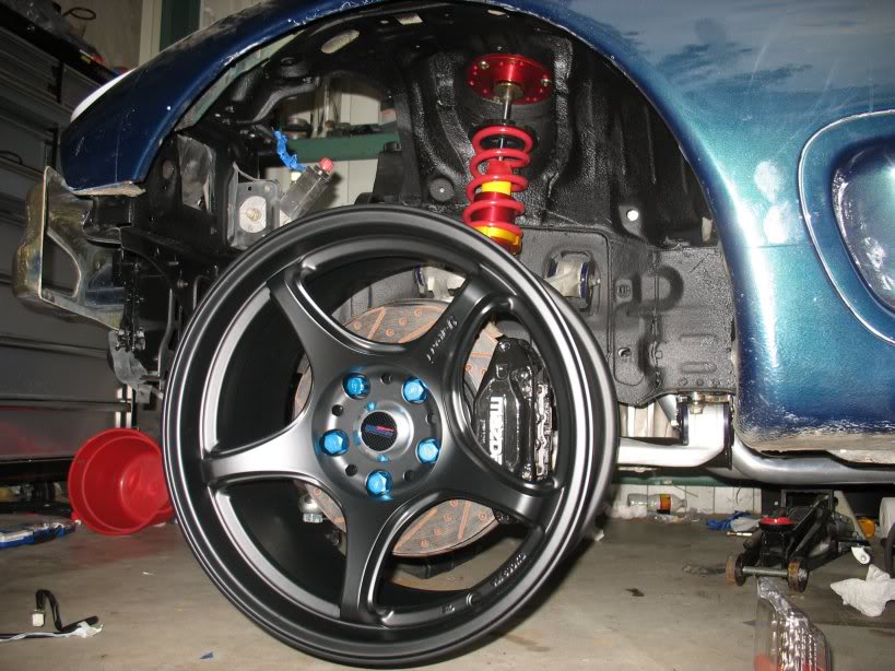
Mocking up a wheel to eyeball how off my toe is
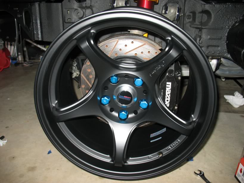
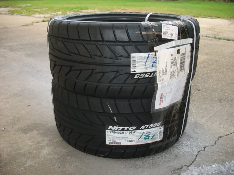
Nittos waiting to be mounted. 275/40/17 for the rear and 255/40/17 for the front
Hawk HP pads masked for anti squeal coating,
Front brakes installed
Another shot. I finally got around to sanding the mazda logo. I really like it since it takes the focus off of my shitty
paint job
The front brake install is about 90% done. I spent an hour trying to figure out how the front hard-lines connected to the
brake MC and ABS unit respectively, until I remembered that the car came without ABS and after looking at some older
pictures I discovered that the stock hard-lines in the fenders had been reformed to make the ABS delete fit better. Guess
I'll be giving Ray some more business :P
Rear brakes installed
Not as pretty as the front, but it'll have to do
Mocking up a wheel to eyeball how off my toe is
Nittos waiting to be mounted. 275/40/17 for the rear and 255/40/17 for the front
Thread Starter
Joined: Apr 2009
Posts: 381
Likes: 27
From: Starkville, MS
Last week I installed my fuel system. I left pictures of the rear to front run out because the stock underbody conduit was
having trouble keeping the lines in place. This weekend I made a few aluminum brackets to help the stock mounting points
out.
Afterwards I spent about 4 hours cleaning up my very very messy shop

I've plunged back into the RX7 wiring harnesses and
don't believe I'll be coming up for air..... At least not for another couple weeks
After a lot of consideration, I've decided to finish what I started and create annotated photos of the Rear Harness, the
Instruments Harness, the Dash Harness, and the Floor Harness. This will be in the same form as the work I did on the Front
Harness:
http://www.norotors.com/index.php?topic=24.0.html
I figure since I already have them stripped down and I'm in the process of labeling everything so I can strip out what isn't
necessary, taking pictures and tagging them in photoshop isn't too much extra trouble. I'm sure good people here will be
glad to have them for reference.
I'm not stripping much out of my harnesses, except for the rear windshield wiper equipment and the whole audio system. What
I'm doing is trying to think everything through so that all my swap wiring will run within the stock harnesses. For example,
my aftermarket alarm will be completely integrated into the Dash Harness
I'm beat. Headed for bed.
Lane
Thread Starter
Joined: Apr 2009
Posts: 381
Likes: 27
From: Starkville, MS
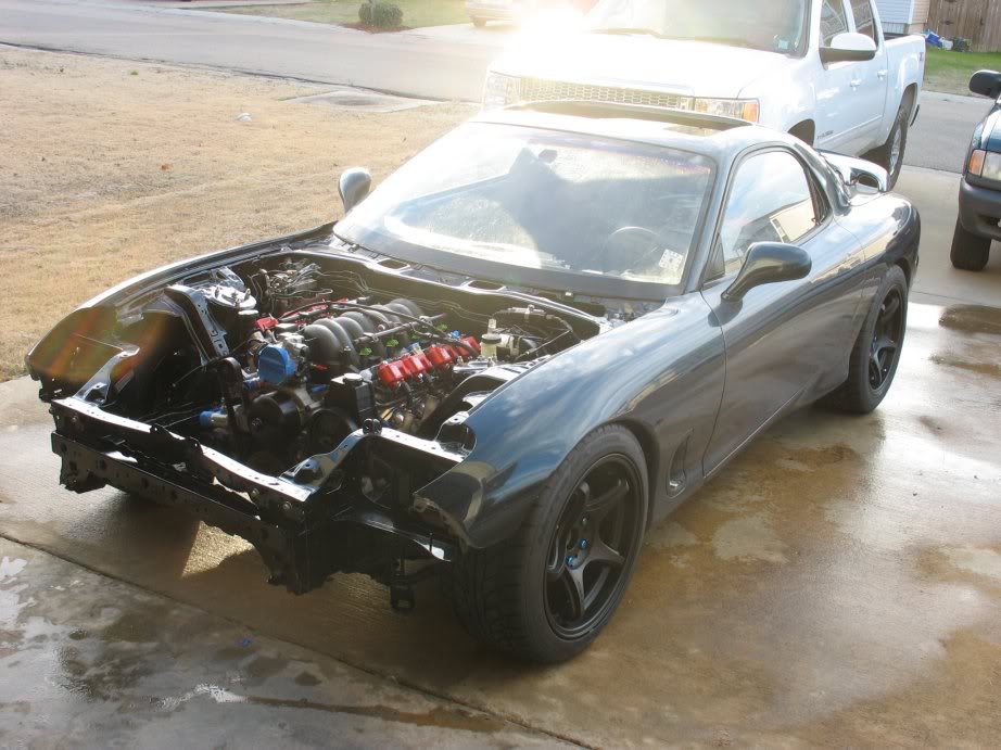
I'm finally in my new home and I've been working on my car over the past few weeks. Here's a few pictures to show what I've
been up to.
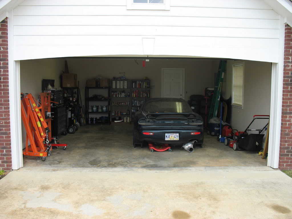
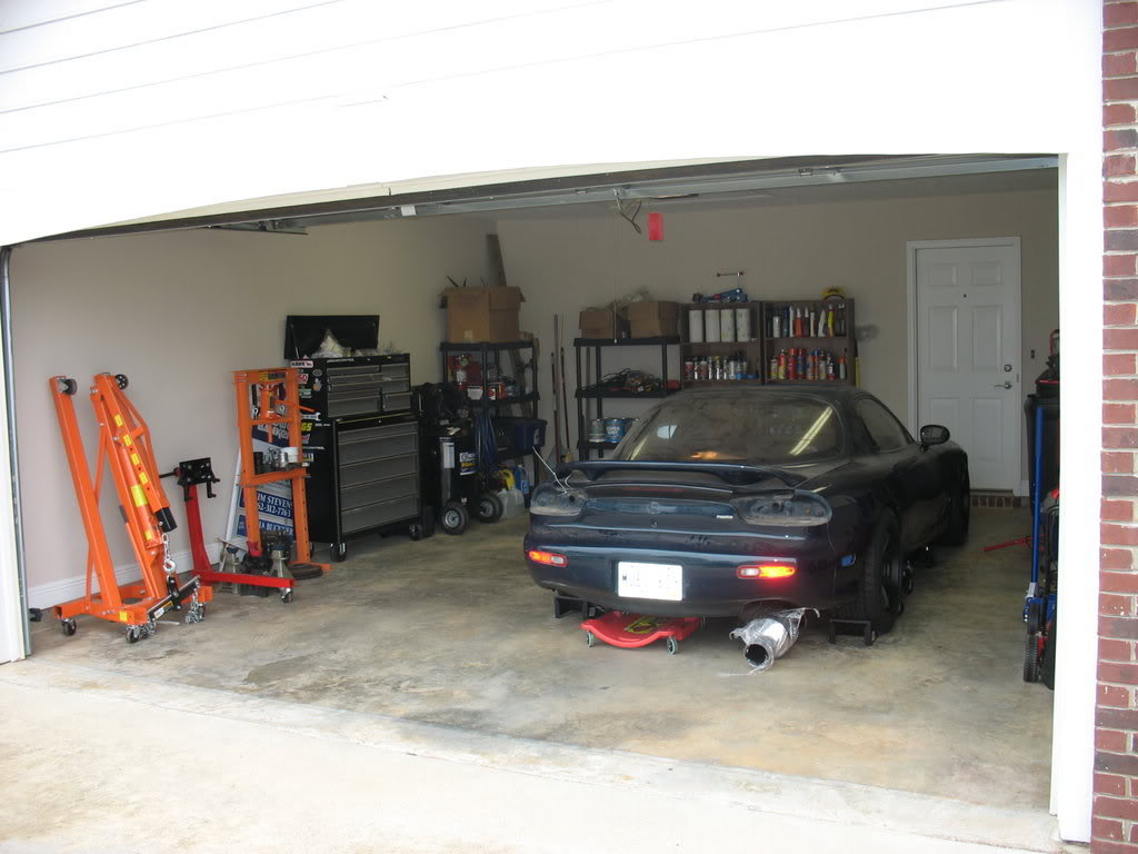
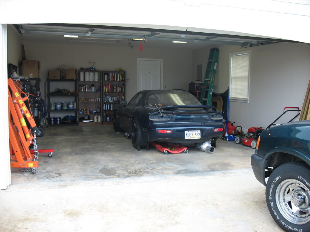
New Garage
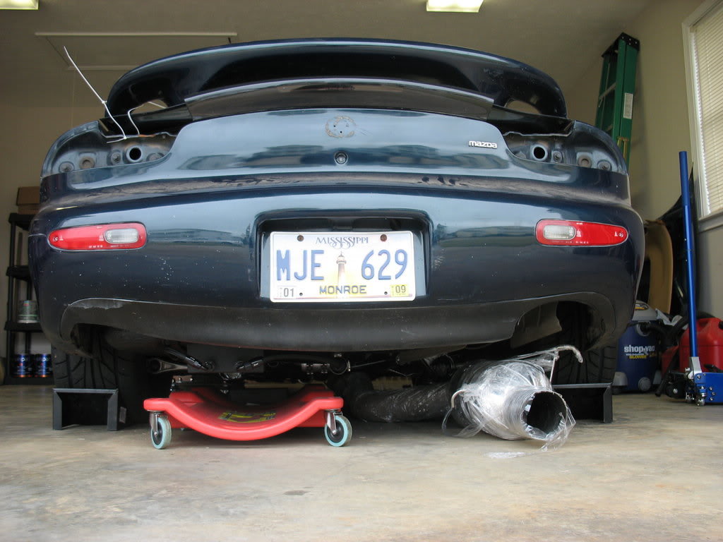
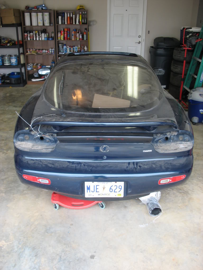
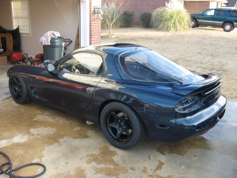
The Dirty Dirty rear end. I feel bad for her. Havn't been able to wash her in almost a year
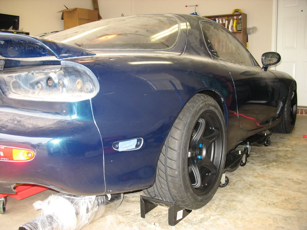
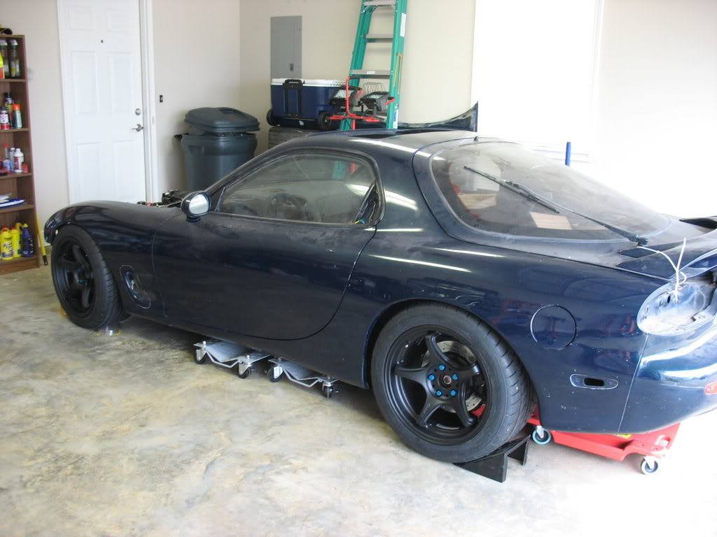
Finally got my suspension and brakes squared away so I could get my wheels on! Ride height is not finished and this is only
eyeball aligned
been up to.
New Garage
The Dirty Dirty rear end. I feel bad for her. Havn't been able to wash her in almost a year
Finally got my suspension and brakes squared away so I could get my wheels on! Ride height is not finished and this is only
eyeball aligned
Thread Starter
Joined: Apr 2009
Posts: 381
Likes: 27
From: Starkville, MS
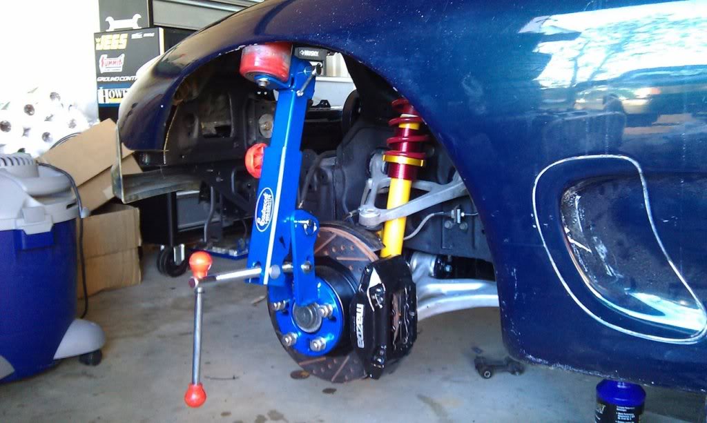
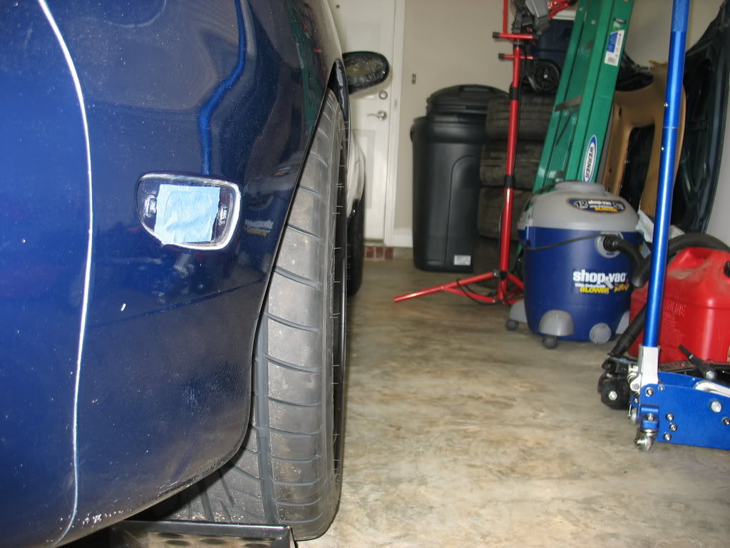
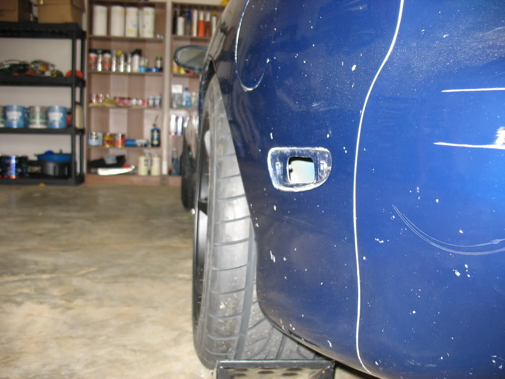
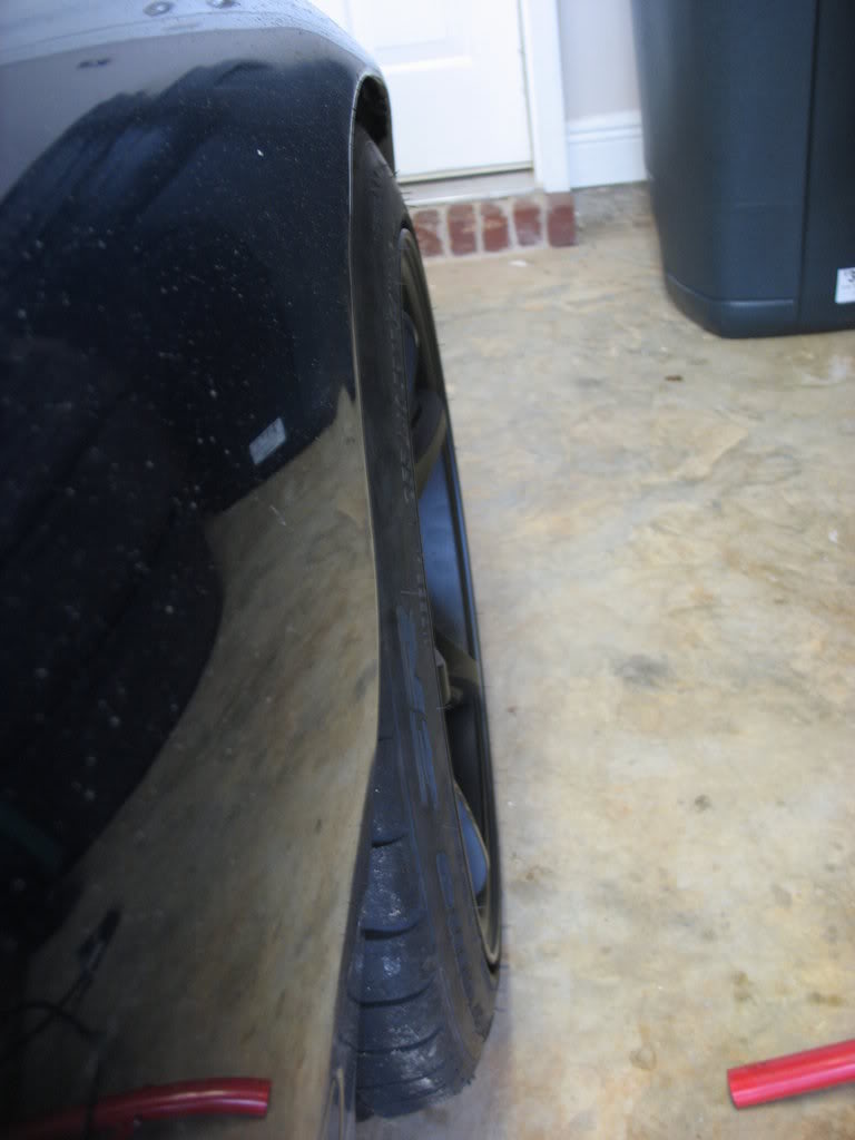
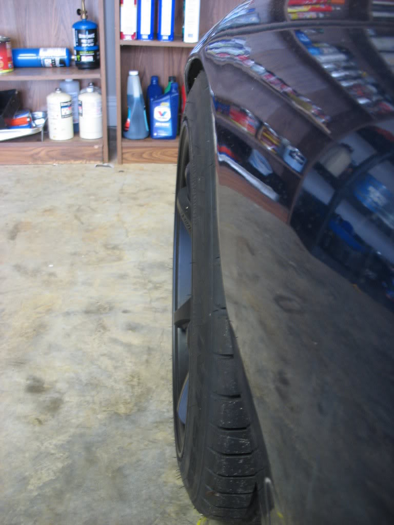
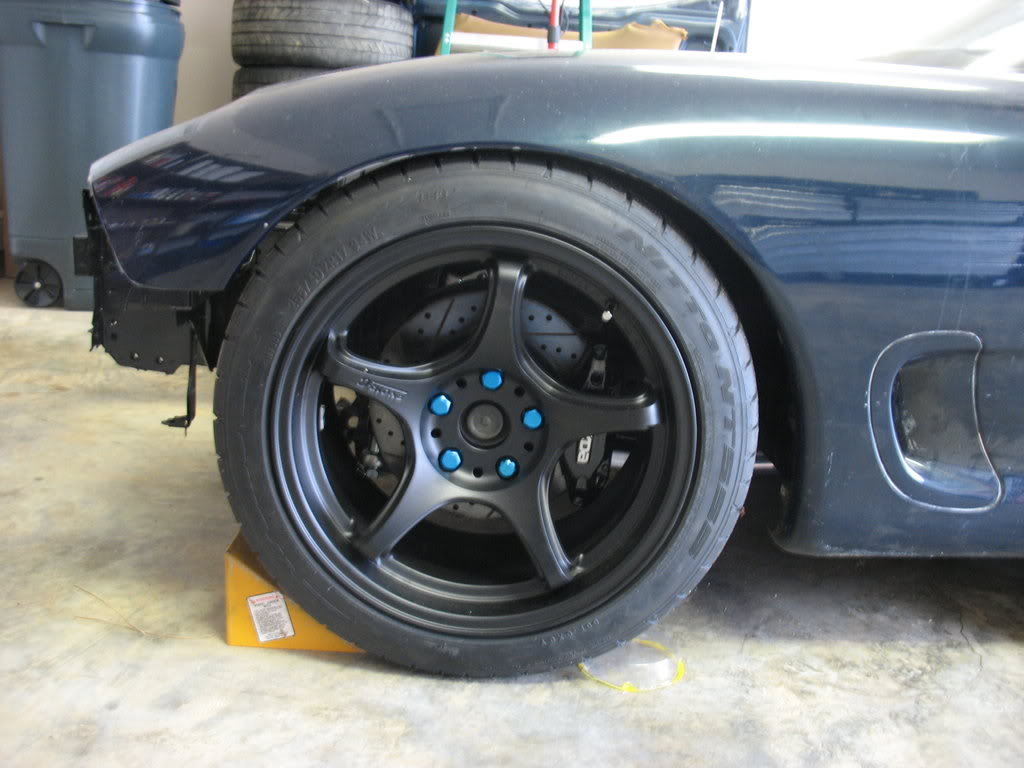
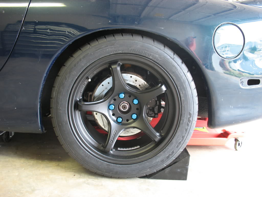
Had to do a fair amount of rolling to get my wheels and tires to clear.
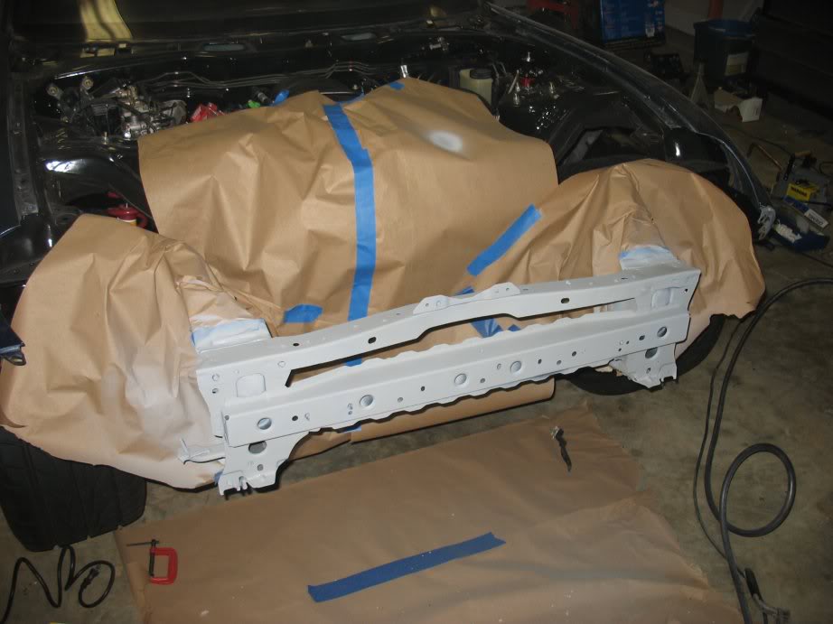
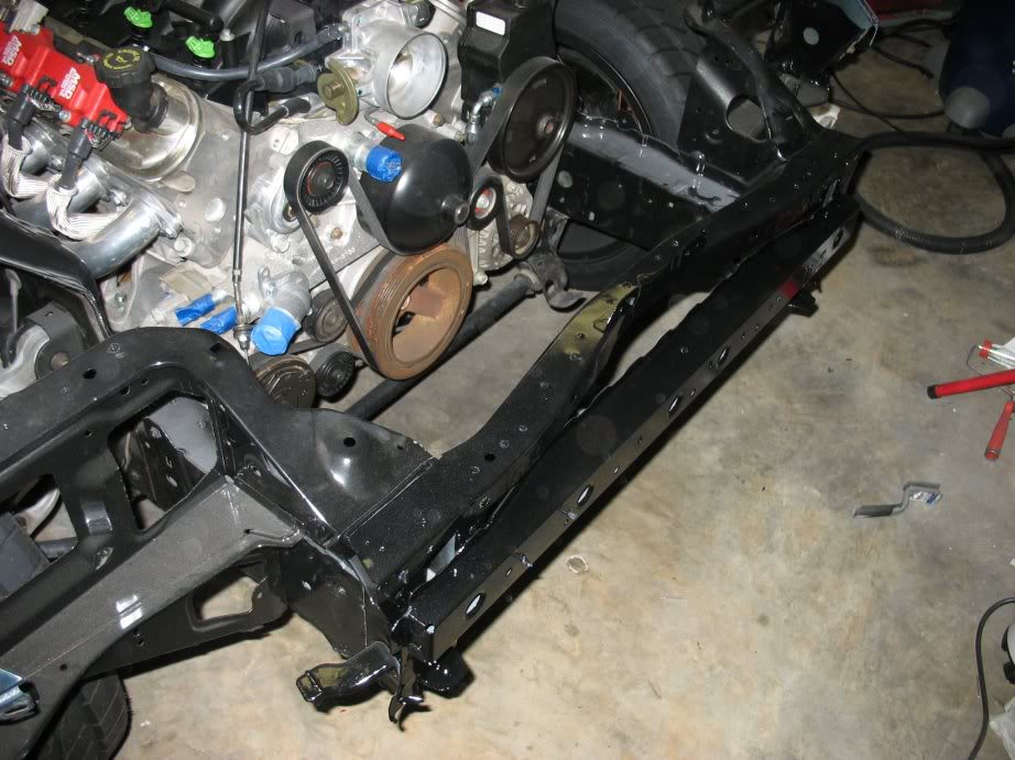
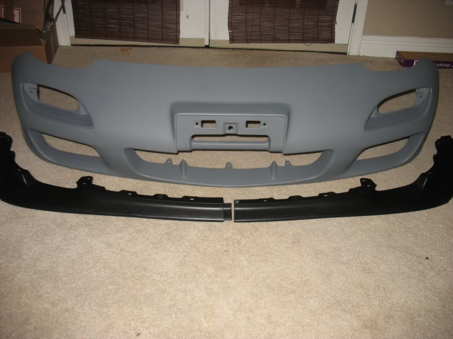
A look at what's going on in the front. Had a little hitch in towing the car to my new garage and tweaked the front crash
bar. Going to get a new one from Ray and have it welded on soon.
Did I mention my brakes are done!?!?! Almost done in this corner as well. Just have to install the master cylinder
Look at all those DEI heat sleeves :yay:
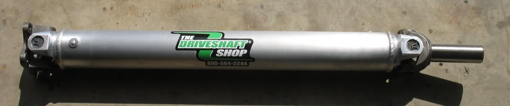
3.5" Aluminum driveshaft custom made by the Drive Shaft shop to fit my Viper T56's 30 spline output and mate it to my Cobra
rear.
Thread Starter
Joined: Apr 2009
Posts: 381
Likes: 27
From: Starkville, MS
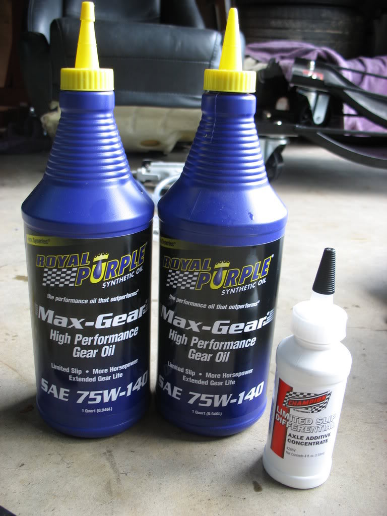
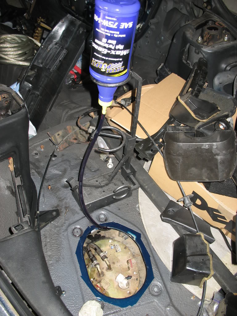
Trans and Diff oiled up!
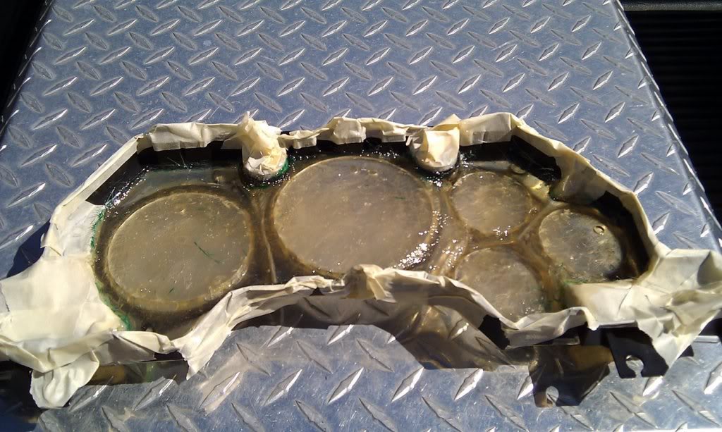
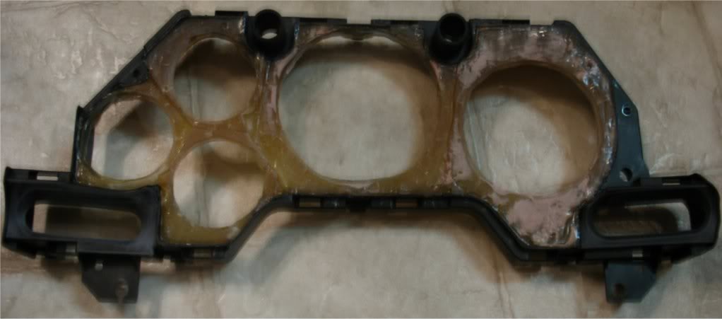
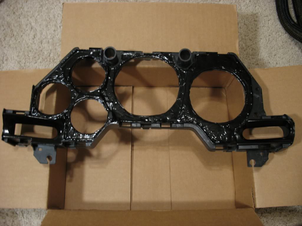
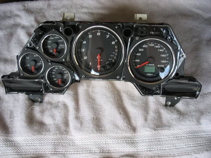
And finally. Something I've been working on for my new Gauges. I'm replacing every gauge in my cluster with speedhut.com
gauges. To make them look stock I'm fabricating a fiberglass section to hold them flush with the stock cluster's front
shield (the part with the chrome rings). Here's my progress so far:
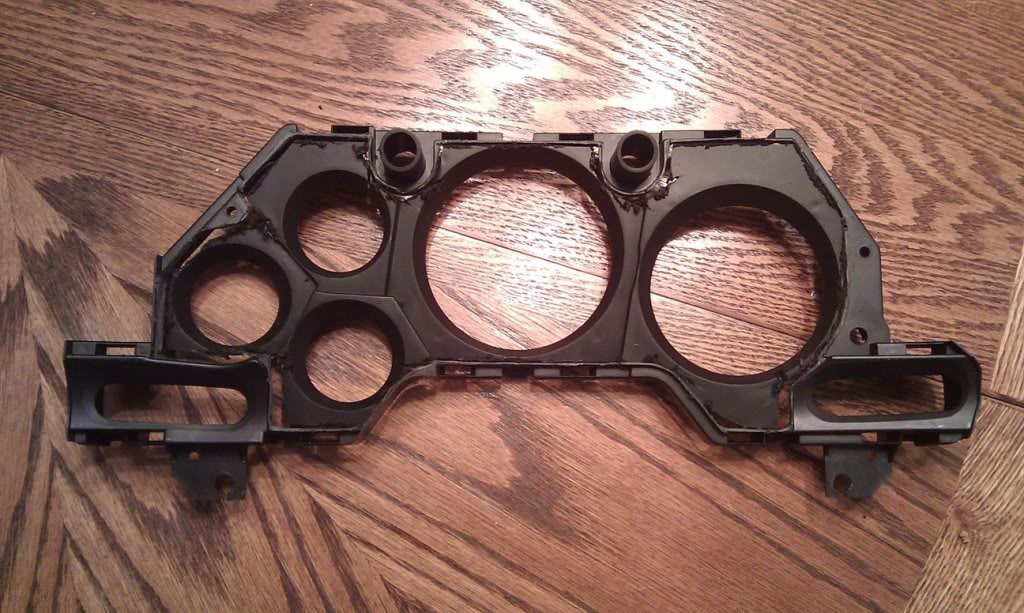
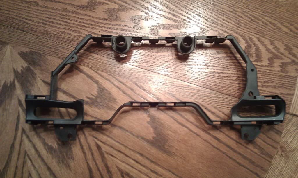
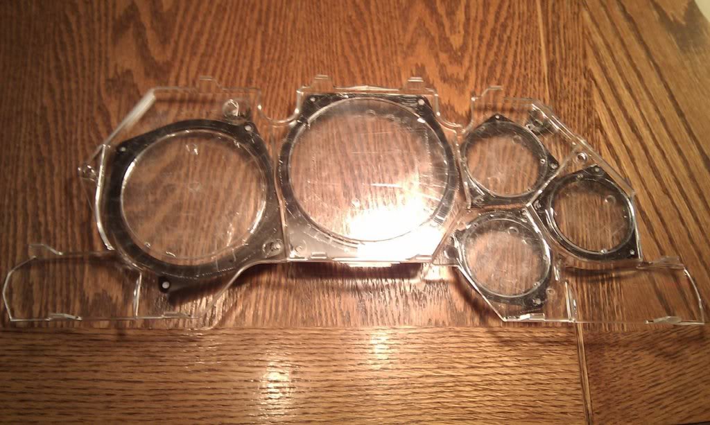
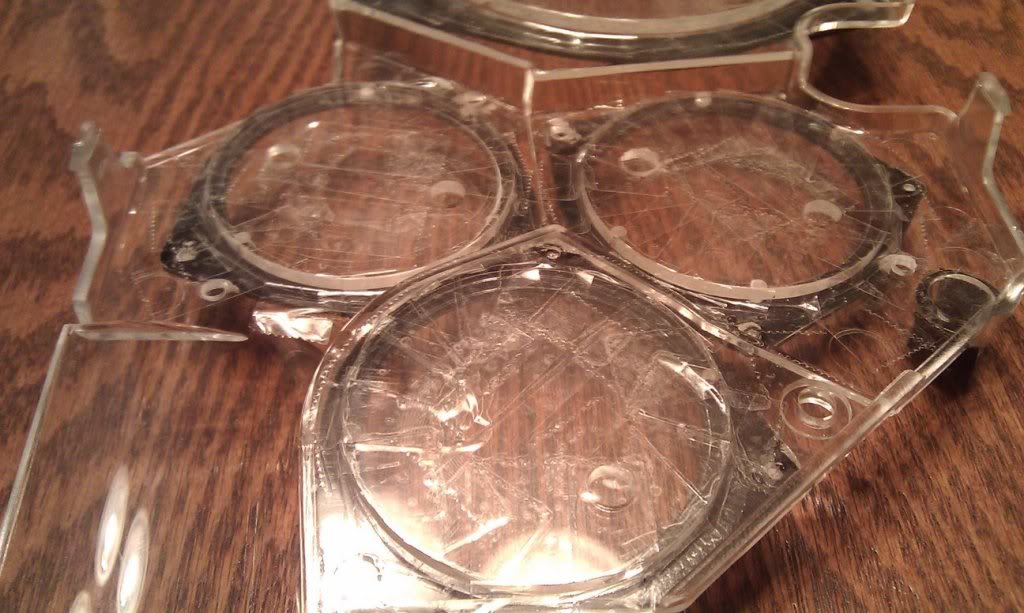
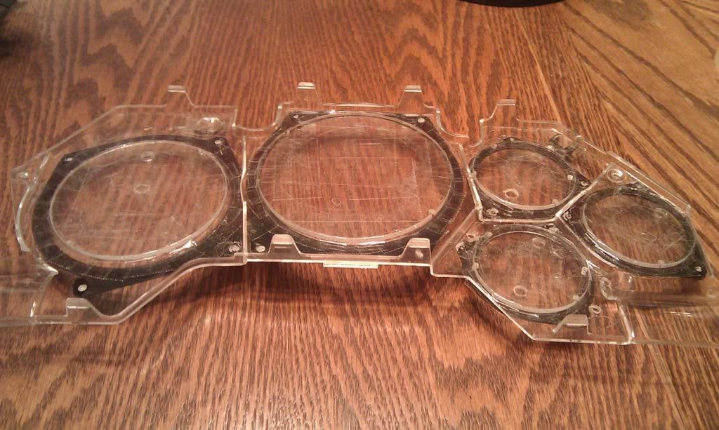
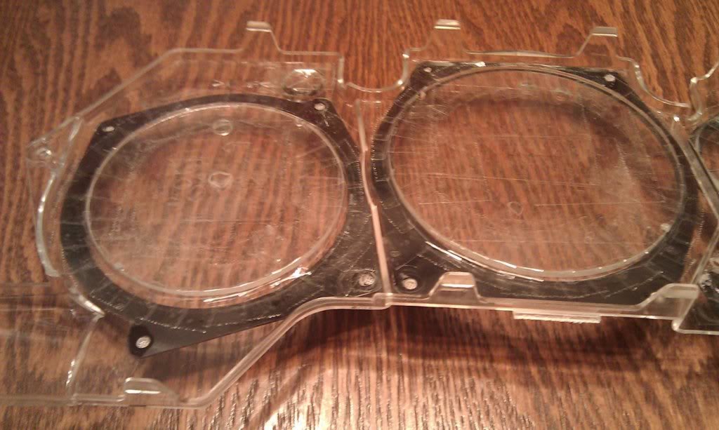
I used the new gauge lenses to form counter-sunk pockets in the fiberglass mold so the gauges can sit flush against the
stock front shield. I taped the lenses down after centering them so they would not move.
Thread Starter
Joined: Apr 2009
Posts: 381
Likes: 27
From: Starkville, MS
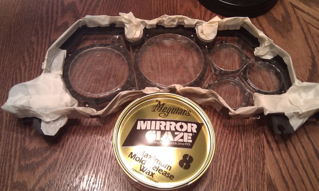
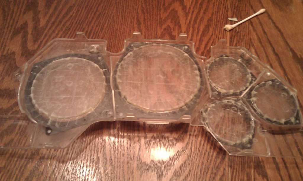
Waxing the 'mold' before laying fiberglass.
Two layers of chop mat.
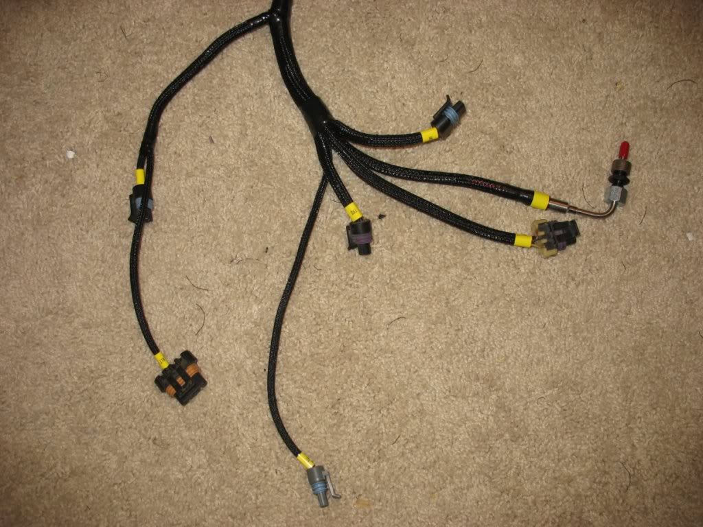
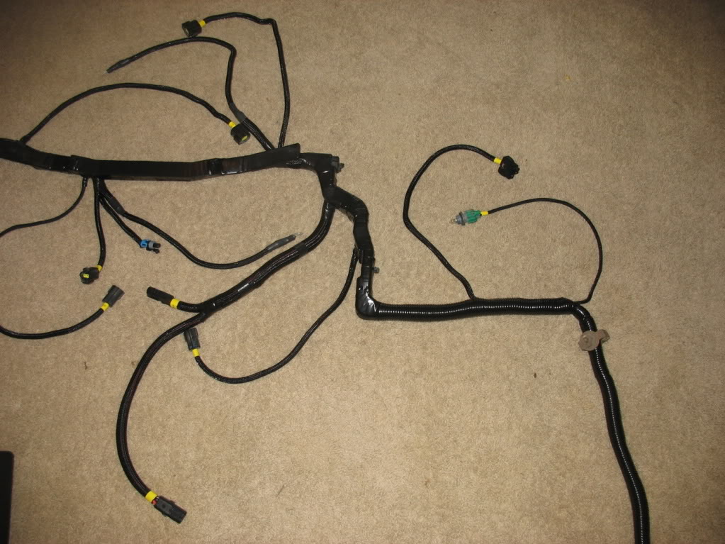
I've been modifying my LS1 harness over the last couple weeks. The first thing I did was frame it to my engine and
accessories by connecting it and zip tying the wire branches to save its form.
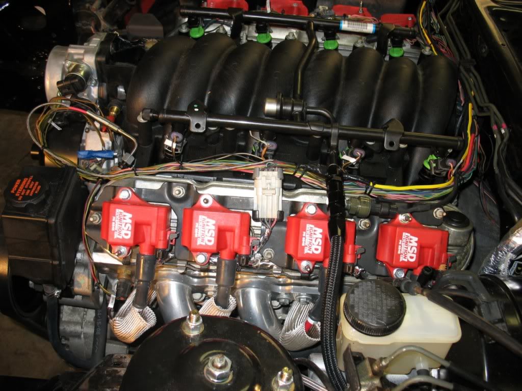
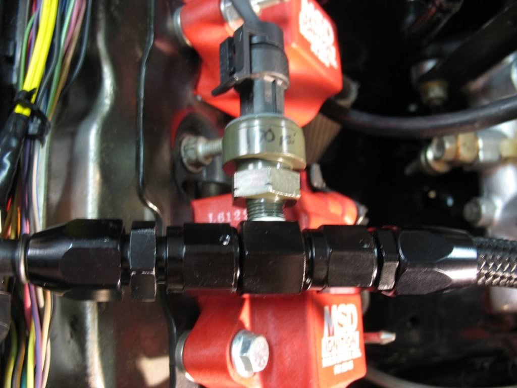
When doing my LS1 harness I also decided to integrate all my aftermarket gauge sensors. Shown below is the fuel pressure
gauge:
Thread Starter
Joined: Apr 2009
Posts: 381
Likes: 27
From: Starkville, MS
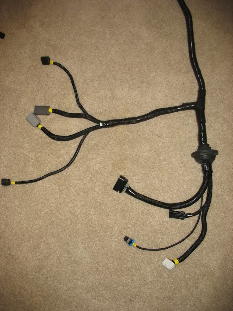
Afterwards I removed the harness and started making the needed modifications... Namely extending the harness so that the PCM
fits underneath the passenger seat.
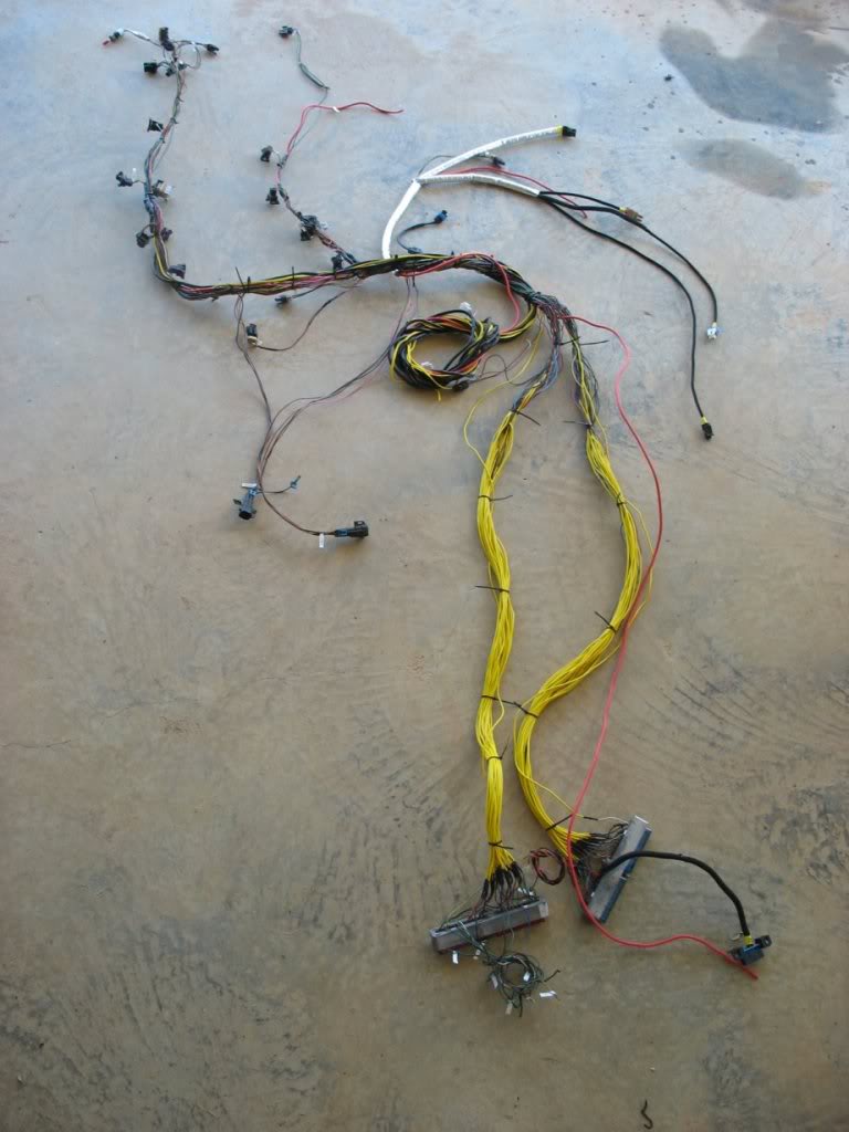
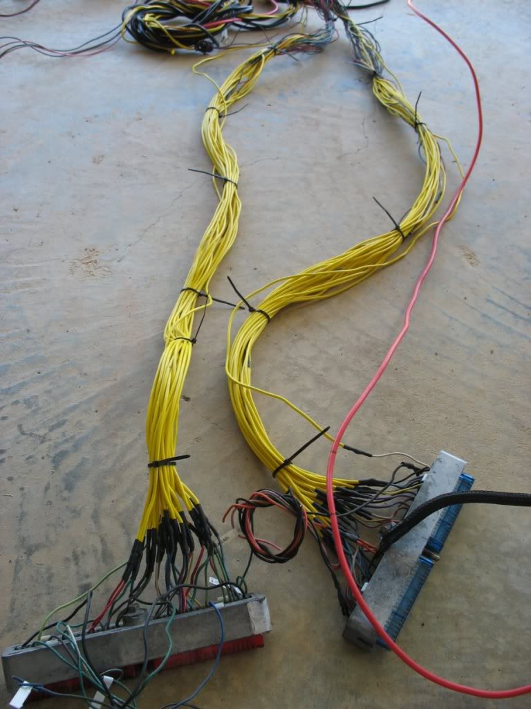
Whew! That extension took A LOT of time
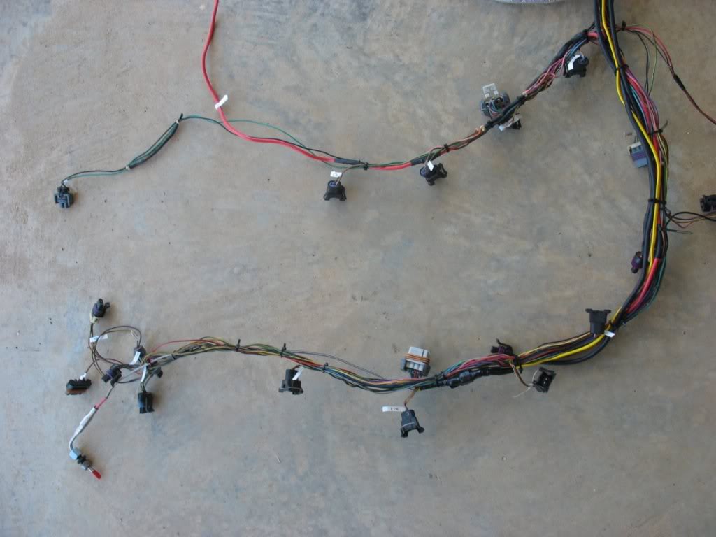
A branch being sleeved
Connector labels. Jealous?
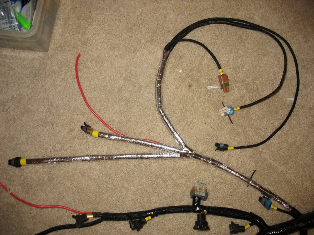
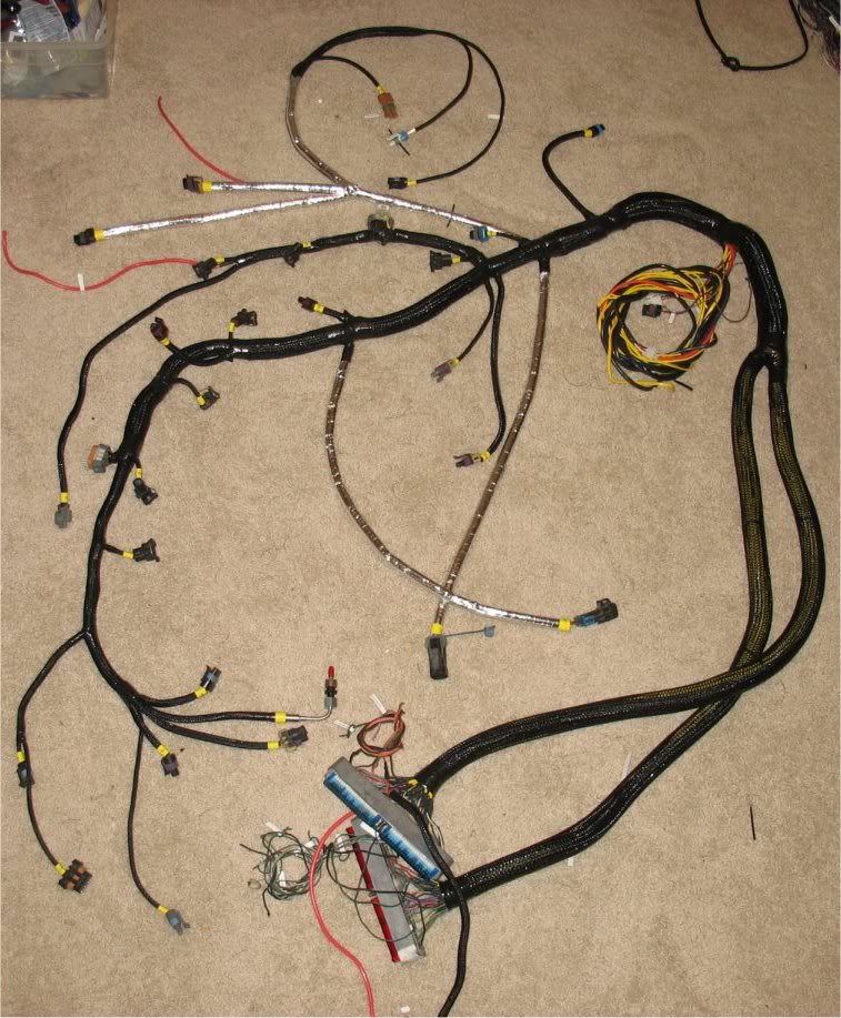
About 90% done. The yellow and black round cable bundle is aftermarket gauge wiring, reverse switch, and check engine light
waiting to be wired to X-14.
The gauge wiring will have a connector at the harness, and male to female intermediate harness, and a connector at the gauge
cluster. All connections will use these 16 pin Delphi GT 150 connectors.
fits underneath the passenger seat.
Whew! That extension took A LOT of time
A branch being sleeved
Connector labels. Jealous?
About 90% done. The yellow and black round cable bundle is aftermarket gauge wiring, reverse switch, and check engine light
waiting to be wired to X-14.
The gauge wiring will have a connector at the harness, and male to female intermediate harness, and a connector at the gauge
cluster. All connections will use these 16 pin Delphi GT 150 connectors.
Thread Starter
Joined: Apr 2009
Posts: 381
Likes: 27
From: Starkville, MS
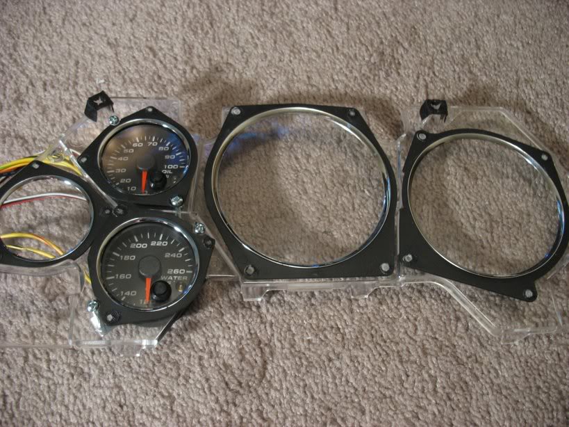
As for the gauges, here are a few pictures to help describe what I am working on.
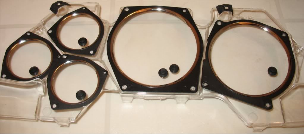
Here is my custom gauge adapter with the gauge holes cut out. If you reference earlier pics, you'll see I molded this piece
using the backside of an old gauge overlay (the clear piece with the chrome rings). I also used the aftermarket gauge faces
in the mold to make counter-sunk pockets for the gauges to sit in. The holes seen in the picture above were cut out 'inside'
the pockets using a diameter ~4mm smaller than the pockets leaving a lip for the gauges to mount to.
Painted, but not really necessary.
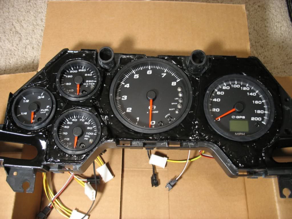
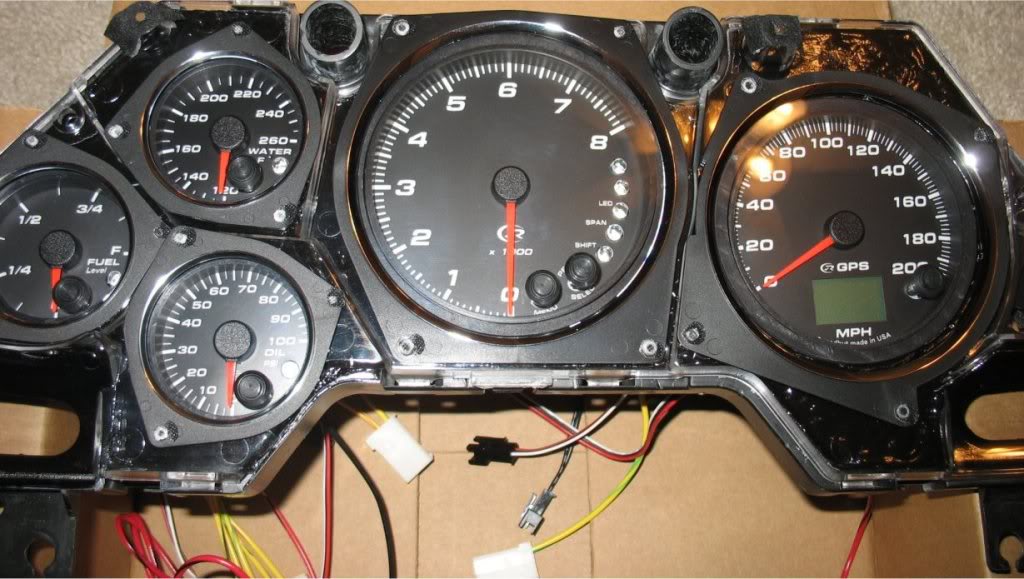
Speedhut gauges in the pockets. This allows the gauges to sit flush against the gauge overlay when it is installed as seen
in the next picture
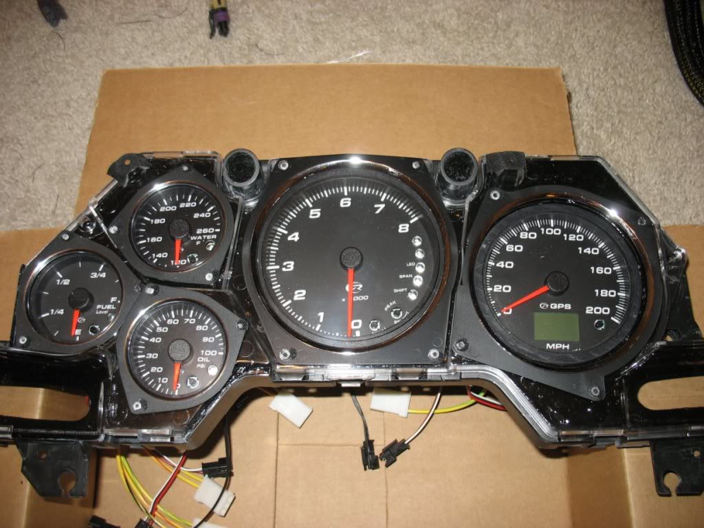
Gauge overlay installed. The only thing remaining is to drill holes in the overlay and install the rubber button caps so the
aftermarket gauge-programming buttons can be accessible from the gauge overlay. It will end up looking exactly how I did my
prototype gauges a few months back as seen below:
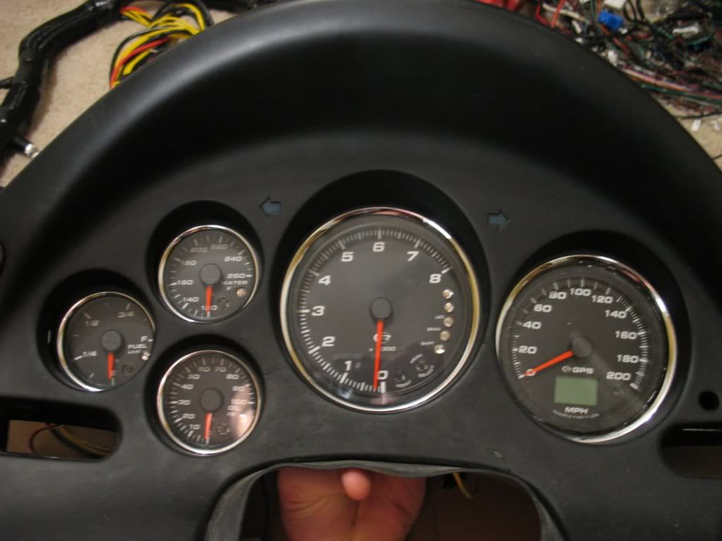
Final look Note that the Tach needle is just off from me jostling the gauge around. Powering it zeros it.
Put up a quick vid of the gauges power up and the blue backlight
I'll post more later today
Lane
Here is my custom gauge adapter with the gauge holes cut out. If you reference earlier pics, you'll see I molded this piece
using the backside of an old gauge overlay (the clear piece with the chrome rings). I also used the aftermarket gauge faces
in the mold to make counter-sunk pockets for the gauges to sit in. The holes seen in the picture above were cut out 'inside'
the pockets using a diameter ~4mm smaller than the pockets leaving a lip for the gauges to mount to.
Painted, but not really necessary.
Speedhut gauges in the pockets. This allows the gauges to sit flush against the gauge overlay when it is installed as seen
in the next picture
Gauge overlay installed. The only thing remaining is to drill holes in the overlay and install the rubber button caps so the
aftermarket gauge-programming buttons can be accessible from the gauge overlay. It will end up looking exactly how I did my
prototype gauges a few months back as seen below:
Final look
Note that the Tach needle is just off from me jostling the gauge around. Powering it zeros it.Put up a quick vid of the gauges power up and the blue backlight
I'll post more later today
Lane
Thread Starter
Joined: Apr 2009
Posts: 381
Likes: 27
From: Starkville, MS
Here are a few pics from the gauge work I did this weekend.
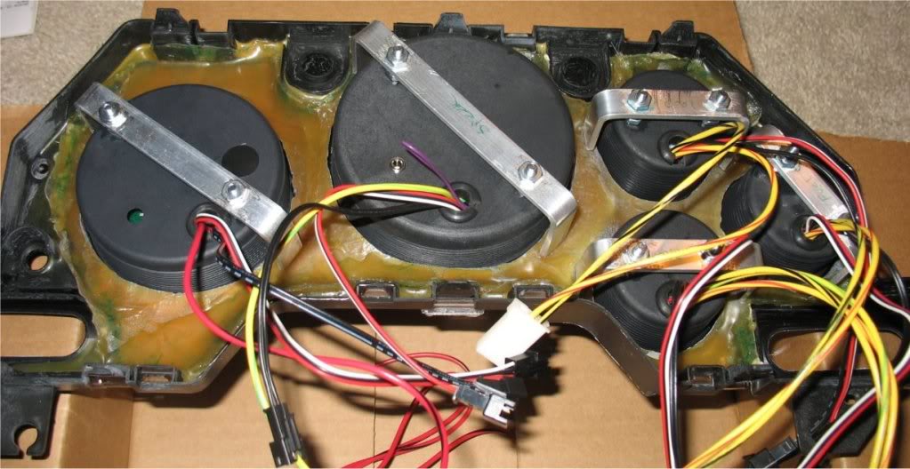
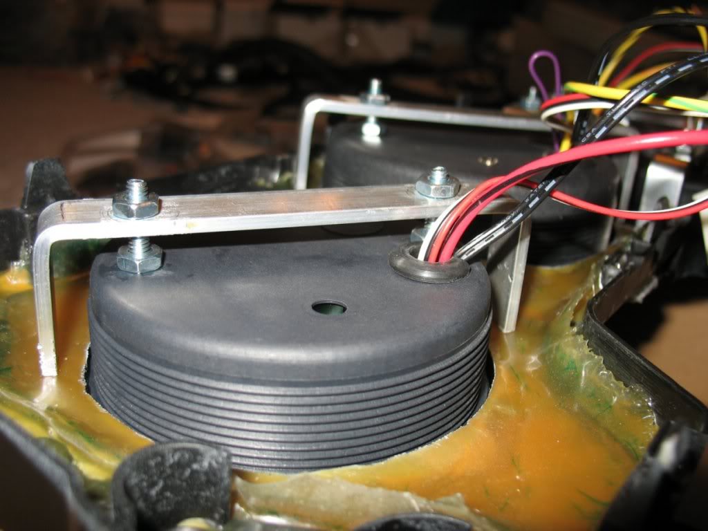
This is a shot of the gauge back. I mounted the gauges using a method a friend showed me. It's basically just aluminum U's,
but I had to add screws to the speedhut gauge housings to make it work.
It was actually a pretty straightforward process and it's very sturdy. The best part is that the mounts have a VERY small
footprint, which is why I abandoned the stock locking collar setup which didn't work because the fiberglass mold back isn't
perfectly flat and because their is very limited space around the gauges. The only downside is that it added additional
depth to the gauges.
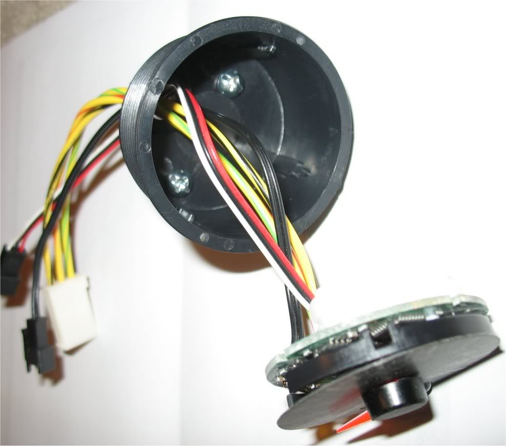
To help with the extra depth I went ahead and created a skeleton gauge back:
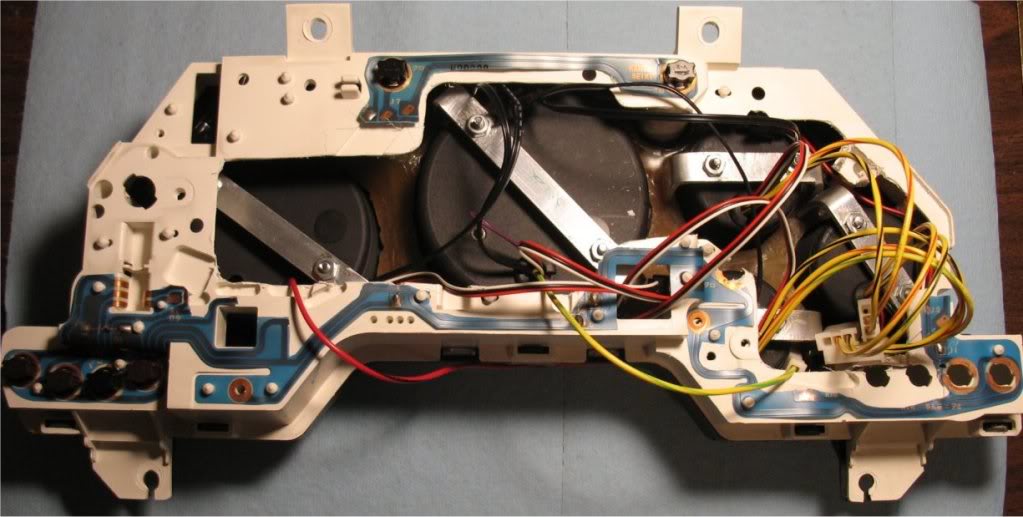
To do this I had to modify the circuit trace to only include traces for the stock functions I still needed. This really only
included indicators and idiot lights. Everything else just got cut out. It looks pretty rough right now, but that's mostly
because I haven't even started to finalize the gauge wiring. The main objective of this weekend was to get everything
physically settled.
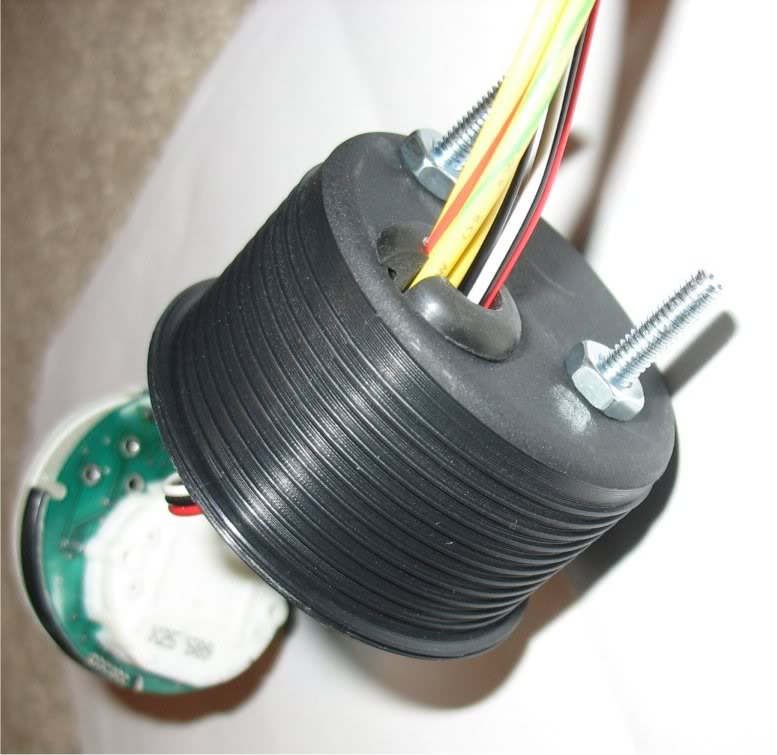
To finish off my work for the weekend I modified the overlay by drilling holes for the program buttons then installing the
grommet-buttons:
The buttons use metal actuator rods to press the speedhut gauge program buttons below:
Finally, in addition to my video above, here is a picture of the gauges backlight

Lane
This is a shot of the gauge back. I mounted the gauges using a method a friend showed me. It's basically just aluminum U's,
but I had to add screws to the speedhut gauge housings to make it work.
It was actually a pretty straightforward process and it's very sturdy. The best part is that the mounts have a VERY small
footprint, which is why I abandoned the stock locking collar setup which didn't work because the fiberglass mold back isn't
perfectly flat and because their is very limited space around the gauges. The only downside is that it added additional
depth to the gauges.
To help with the extra depth I went ahead and created a skeleton gauge back:
To do this I had to modify the circuit trace to only include traces for the stock functions I still needed. This really only
included indicators and idiot lights. Everything else just got cut out. It looks pretty rough right now, but that's mostly
because I haven't even started to finalize the gauge wiring. The main objective of this weekend was to get everything
physically settled.
To finish off my work for the weekend I modified the overlay by drilling holes for the program buttons then installing the
grommet-buttons:
The buttons use metal actuator rods to press the speedhut gauge program buttons below:
Finally, in addition to my video above, here is a picture of the gauges backlight
Lane
Thread Starter
Joined: Apr 2009
Posts: 381
Likes: 27
From: Starkville, MS
It’s been so long since I’ve posted an update that I made a big effort to end my weekend with one
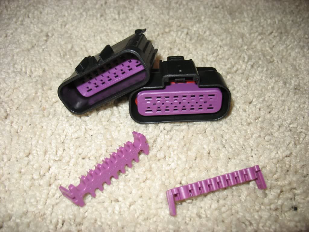
Since the last time I posted pictures I have completed and tested my gauge cluster, which basically boiled down to finishing
up the backside. Since I’m modifying my dash and instrument harnesses I wasn’t stuck with the stock cluster connectors and I
went with a 22 pin Delphi latching connector for a single plug-n-play connection:
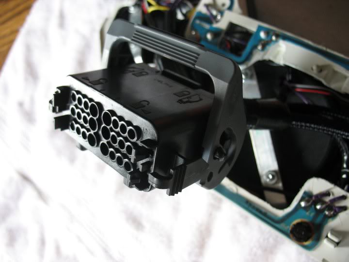
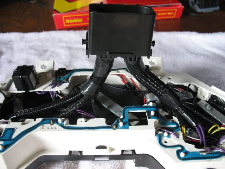
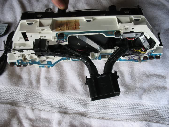
Finally done
A few weeks ago I spent some time repairing my front crash bar. Due to a towing accident, which is all my fault because I
thought using the crash bar would be ok for a short tow, my crash bar looked like this:

After getting a replacement from Ray I drilled out the original spot welds and welded the new one back on. Since I had
removed a lot of paint to spot weld the new bar on; I primed and painted the new one.
At this point I was fed up with how dusty my car was getting so I rolled it out for a sponge bath since my car is so
stripped :P
Much better
Since the last time I posted pictures I have completed and tested my gauge cluster, which basically boiled down to finishing
up the backside. Since I’m modifying my dash and instrument harnesses I wasn’t stuck with the stock cluster connectors and I
went with a 22 pin Delphi latching connector for a single plug-n-play connection:
Finally done
A few weeks ago I spent some time repairing my front crash bar. Due to a towing accident, which is all my fault because I
thought using the crash bar would be ok for a short tow, my crash bar looked like this:
After getting a replacement from Ray I drilled out the original spot welds and welded the new one back on. Since I had
removed a lot of paint to spot weld the new bar on; I primed and painted the new one.
At this point I was fed up with how dusty my car was getting so I rolled it out for a sponge bath since my car is so
stripped :P
Much better
Thread Starter
Joined: Apr 2009
Posts: 381
Likes: 27
From: Starkville, MS
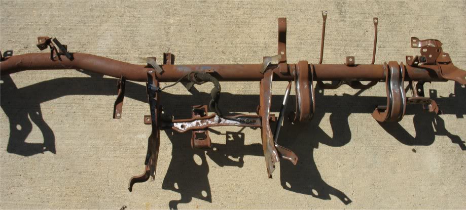
Yet another weekend I decided that something had to be done with the rusty dash support brace…
As it was:
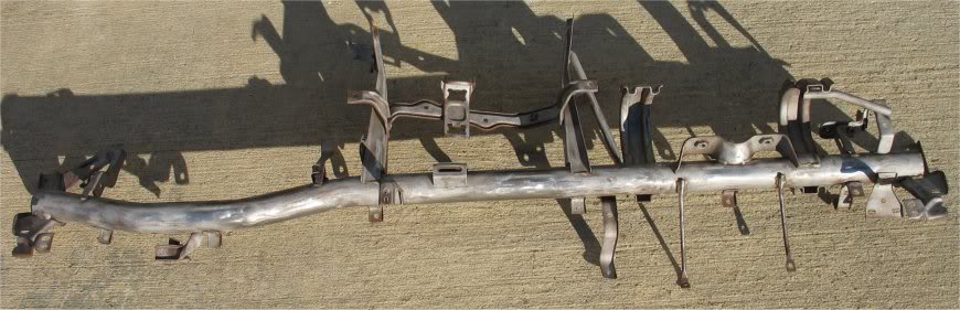
Sandblasted:
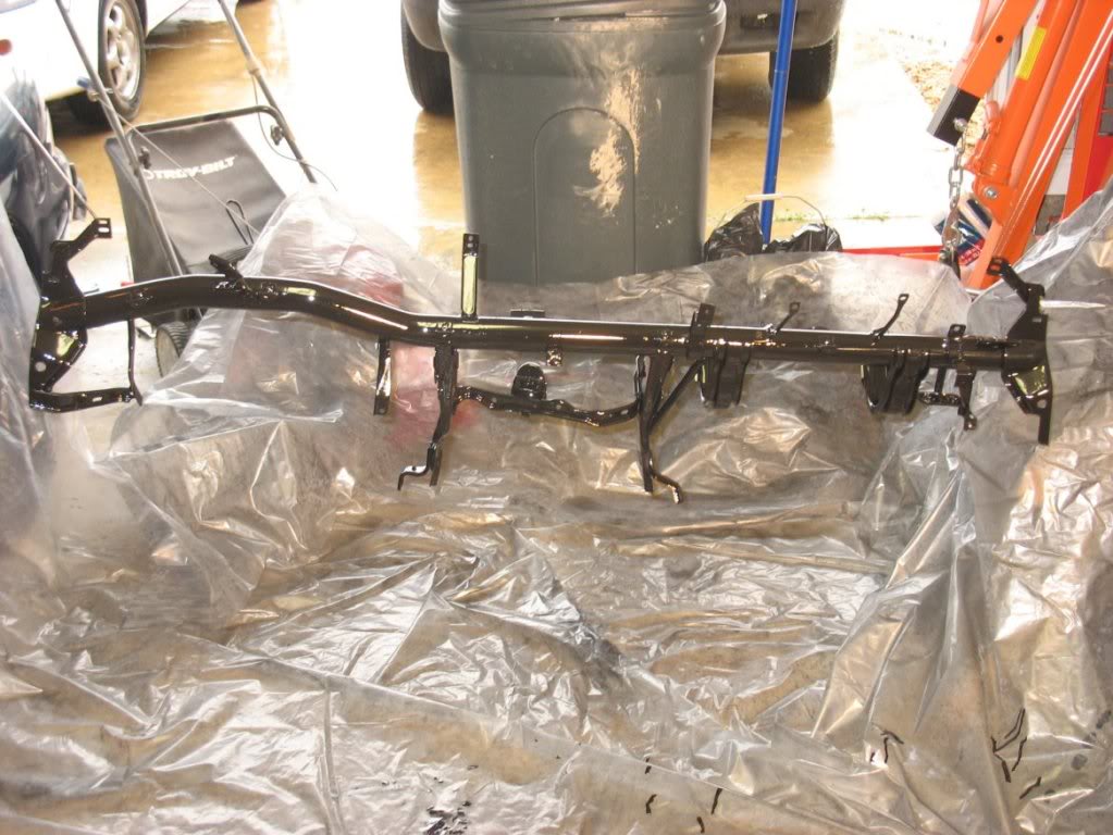
Freshly coated with Semi-gloss POR15
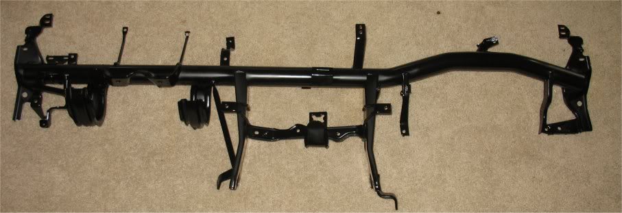
Cured
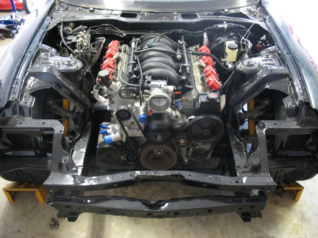
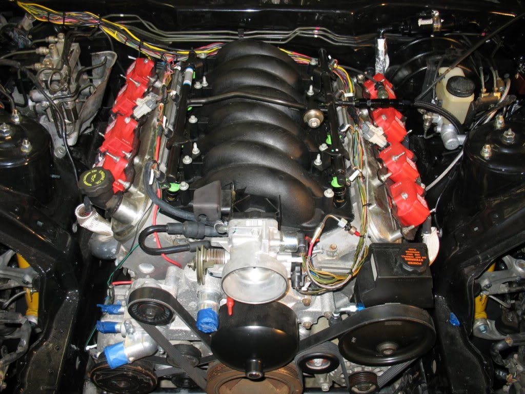
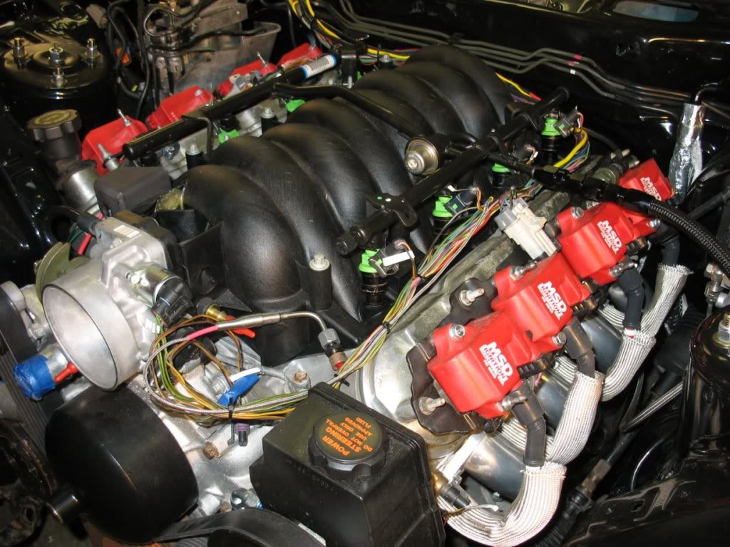
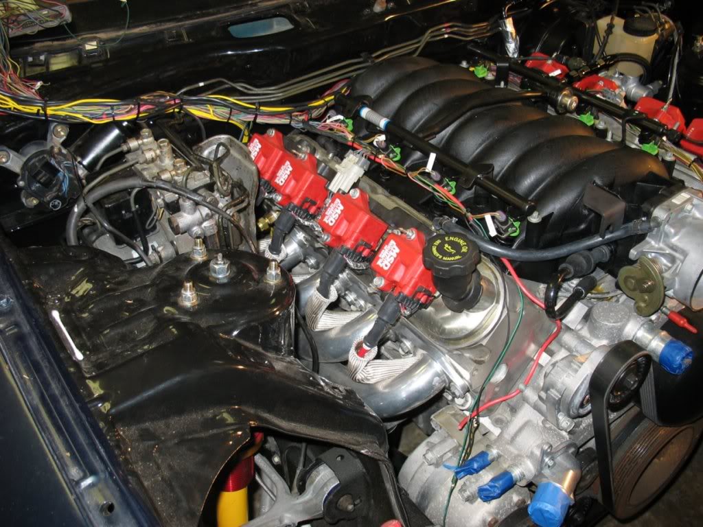
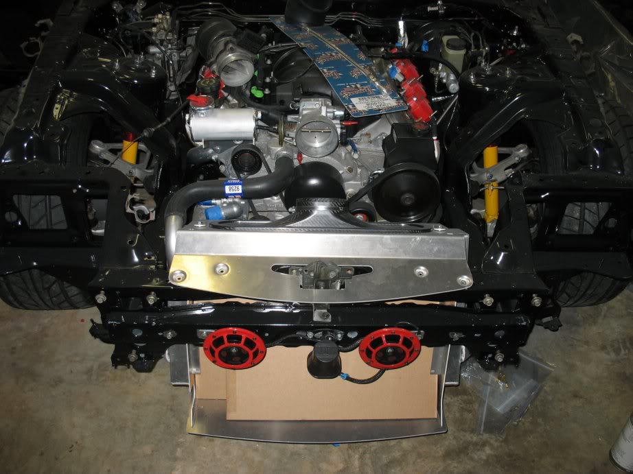
Here’s my engine bay as it sits tonight:
I managed to get my Samberg V2 radiator partially installed a few weeks ago along with my front harness (big step for me
cause this harness has been out for a year now). After wiring up my horns and alarm siren I decided that I really wanted a
better fuse / relay box solution, so I ripped the front harness back out and started the process of building one.
Unfortunately, I didn’t take pictures of the harness installed, which is a shame because it was fully sleeved and looking
pretty
That pretty much brings me back to my project’s ultimate “scale creep” . . . wiring.
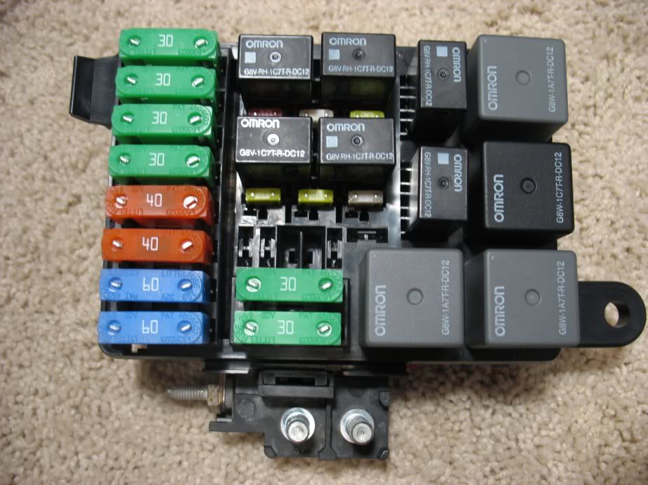
About 6 months ago I posted a small tutorial here that covered the construction of a fused relay box like this:
My plan was to homerun the circuits it controlled to one of the storage bins…
At the time, it was the result of not being able to find a small OEM fuse/relay box with support for 7 relays and 6 fuses
and I thought my work was top notch. Haha! Well, Pez came in and told me what I could have done better and showed me a
couple of pictures of boxes he’d built from scratch which really put my box to shame. At the time I got angry because his
solution is what I spent weeks looking around for + I’d spent a weekend building my box, so I was childish, said some rude
things to Greg (I’ve since apologized), and took the thread down lol! But, that was just me not being able to take
constructive criticism…. Everything Greg said was true and much more elegant than what I designed, so in the end, it’s what
I decided to go with for my primary fuse/relay box and the reason I ripped out my front harness after “finishing” it.
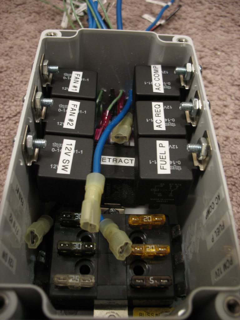
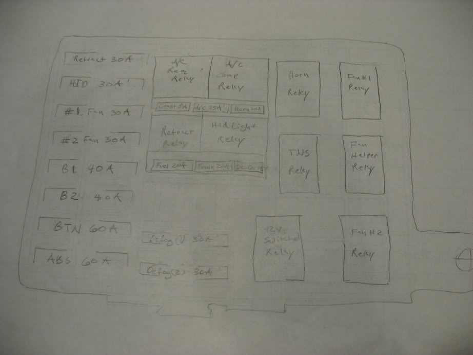
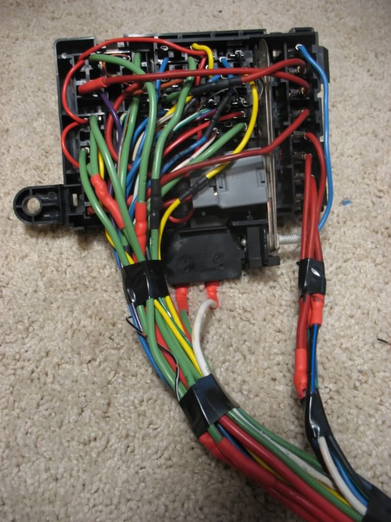
Here are some in-process pictures of the Delphi fuse/relay box I’m building from scratch:
My layout supports 16 fuses and 10 relays and I’m using every one lol!
Basic backside power routing (it’s currently much messier now)
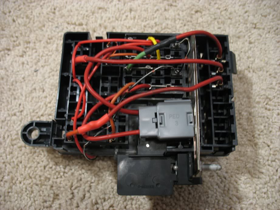
A sheet I drew to keep track of what’s what:
As it was:
Sandblasted:
Freshly coated with Semi-gloss POR15
Cured
Here’s my engine bay as it sits tonight:
I managed to get my Samberg V2 radiator partially installed a few weeks ago along with my front harness (big step for me
cause this harness has been out for a year now). After wiring up my horns and alarm siren I decided that I really wanted a
better fuse / relay box solution, so I ripped the front harness back out and started the process of building one.
Unfortunately, I didn’t take pictures of the harness installed, which is a shame because it was fully sleeved and looking
pretty
That pretty much brings me back to my project’s ultimate “scale creep” . . . wiring.
About 6 months ago I posted a small tutorial here that covered the construction of a fused relay box like this:
My plan was to homerun the circuits it controlled to one of the storage bins…
At the time, it was the result of not being able to find a small OEM fuse/relay box with support for 7 relays and 6 fuses
and I thought my work was top notch. Haha! Well, Pez came in and told me what I could have done better and showed me a
couple of pictures of boxes he’d built from scratch which really put my box to shame. At the time I got angry because his
solution is what I spent weeks looking around for + I’d spent a weekend building my box, so I was childish, said some rude
things to Greg (I’ve since apologized
), and took the thread down lol! But, that was just me not being able to take constructive criticism…. Everything Greg said was true and much more elegant than what I designed, so in the end, it’s what
I decided to go with for my primary fuse/relay box and the reason I ripped out my front harness after “finishing” it.
Here are some in-process pictures of the Delphi fuse/relay box I’m building from scratch:
My layout supports 16 fuses and 10 relays and I’m using every one lol!
Basic backside power routing (it’s currently much messier now)
A sheet I drew to keep track of what’s what:
Thread Starter
Joined: Apr 2009
Posts: 381
Likes: 27
From: Starkville, MS
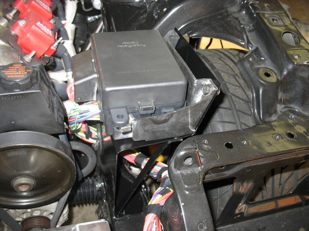
This fuse / relay box replaced X-01, X-02, the front relay box, and the loose fan & headlight relays in the engine bay.
Plus, it gives me relays and fuses to control things like AC, Fuel Pump, Fans, etc. I will be mounting it near the driver’s
fender close to where the stock fuse boxes mount.
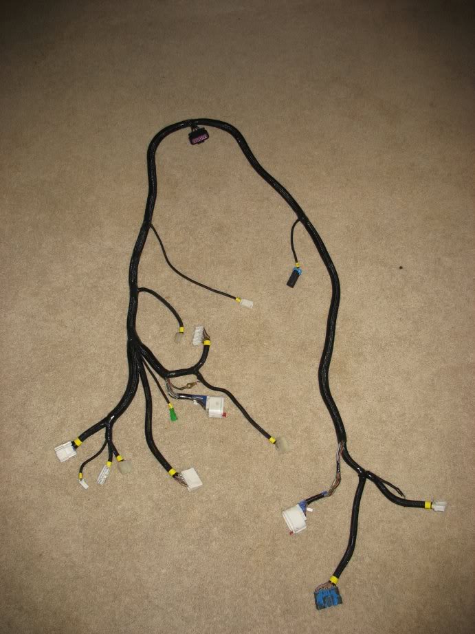
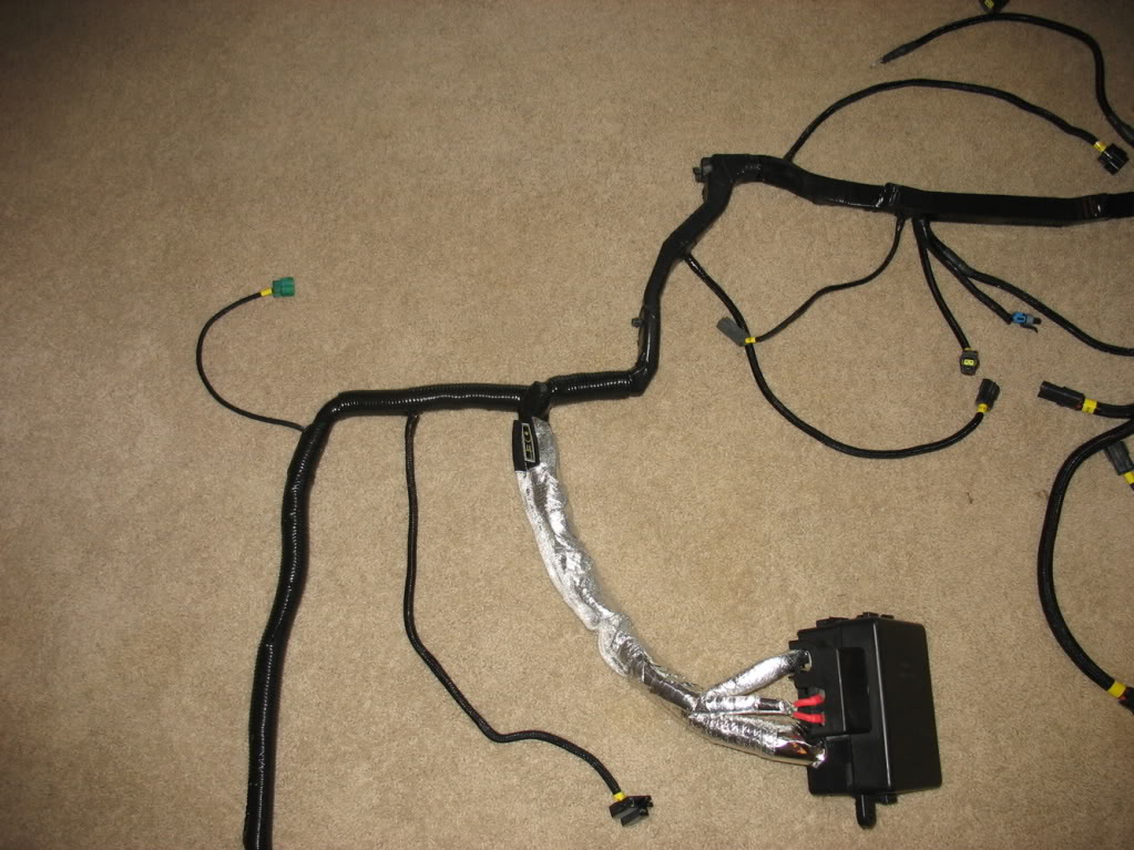
Other than that, the only thing I’ve wrapped up recently was my dash harness:
My instrument harness is still being modified for my new gauge cluster.
My engine harness is waiting for Pez to send me a bunch of wiring so I can extend it 8ft to the passenger bin. Its injector
feeds are also being modified to interface with my racelogic TC system and various circuits are being routed to interface
with the stock front harness, and instrument harness.
Finally, my rear harness is waiting to have the bose circuits stripped, a trunk popper grafted in, and a small relay box
installed.
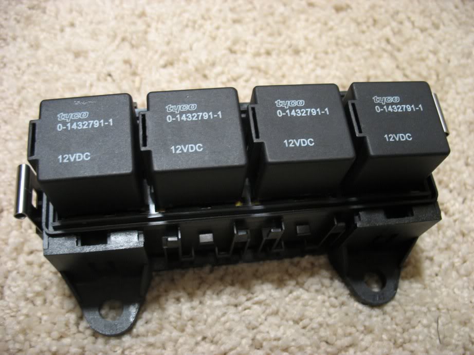
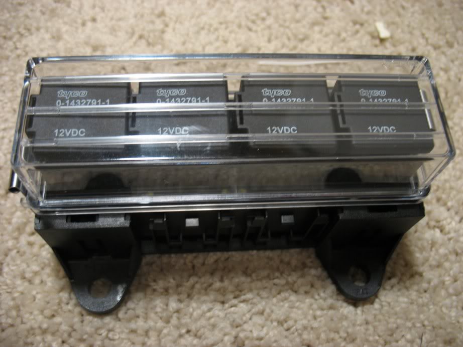
These are just relays I couldn’t fit in my primary box, although their fuses are located there. Two of them split the duty
of the defroster (separately fused). The other two handle the fuel pump and the trunk popper. The box will be mounted near
the ABS controller very close to where the stock defroster relay mounted.
That’s pretty much it… Wiring paired with my indecisiveness is definitely the biggest holdup of my project. Oh well, I’ll
finish someday.
Oh yeah, looky what UPS finally brought me
I was asked in the other forum where I got the parts that were used to build my new fuse/relay box.
Mouser.com gentlemen.... Mouser.com
Basic Box Parts:
829-12146281
829-12146286
829-12162365
829-12160765
829-12077532
829-12146283
829-12146284
Relays
Omron SPDT Micro = 653-G8V-RH-1C7TRDC12 - Love these!!!
Omron SPST Mini = 653-G8W1A7TRDC12
Omron SPDT Mini = 653-G8W1C7TRDC12
Terminals:
Maxifuse Terminals = 829-12110127 - You'll need at least 8
Relay terminals (except for center section relays) - 829-12110844 & 829-12129424 - I bought > 50 of each type. The only
difference between the two is the wire gauges they support. More options and part numbers are available in the datasheets on
mouser.com, but beware of just looking for Female Metri-Pack 280 terminals because there are at least TWO types. The only
type that works in this electrical center is the type that uses "Friction" as the locking mechanism. The "Tang" type DO NOT
work. Ask me how I know
Center section terminals - 829-12110646 - I bought > 50 of these as well. These are bussed, which means they will come wired
together. It's nice because it allows you to make mini power busses in the center section and simplify wiring, but it's also
a small hassle because it means you have to snip them apart (I use shears) when doing singles.
Fuses:
Maxi:
576-0299030.ZXNV - 30A
576-0299040.ZXNV - 40A
576-0299060.ZXNV - 60A
Mini:
576-0297010.WXNV - 10A
576-0297015.WXNV - 15A
576-0297020.WXNV - 20A
576-0297025.WXNV - 25A
576-0297030.WXNV - 30A
The parts above are about 85% of what you need. Unfortunately, Delphi has discontinued a very important part of the box...
The Power distribution block / stud:
http://connectors2.delphi.com/dcsgdmcs/del/attachments/2D Drawings (TIF Format)/12146285_CUS01_S01.tif
To complicate matters, you'll see that mouser is currently out of stock when it comes to the box cover and some of the
locks. To get around this, I bought a used pre-constructed box from eBay:
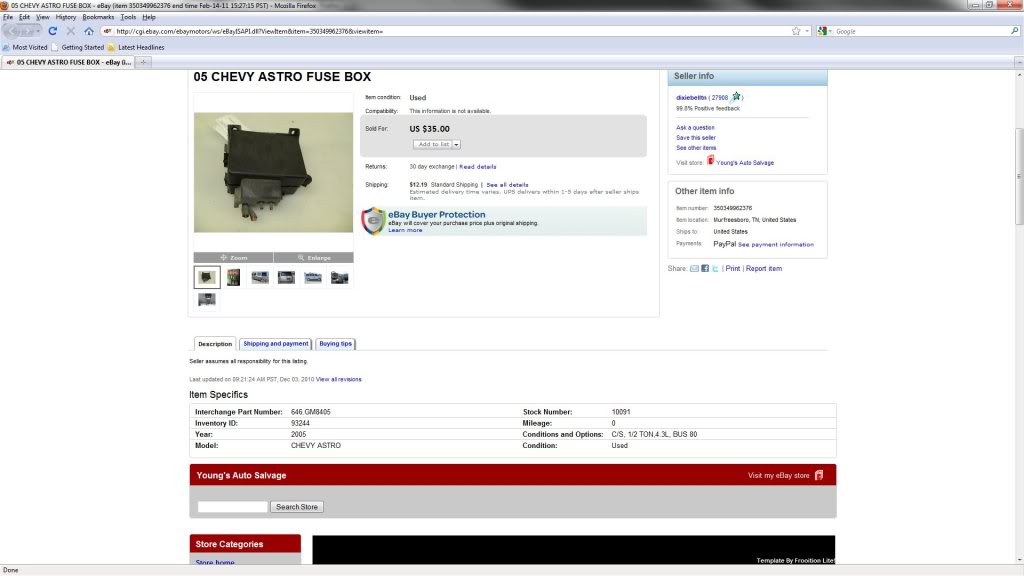
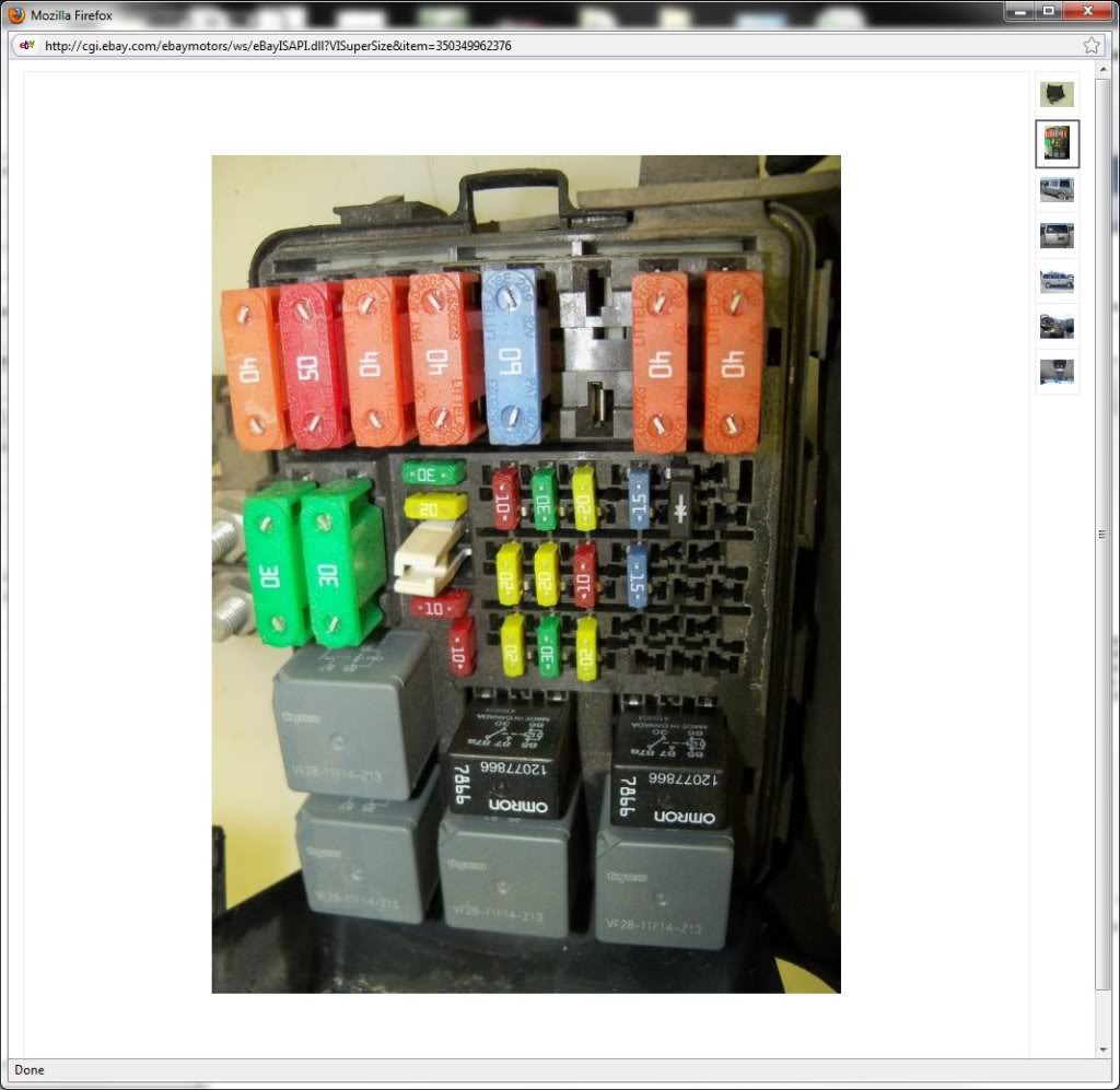
The idea was to salvage a couple of parts I couldn't purchase anymore, but still have a mostly new fue/relay box in the end
If you want to do the same thing I did, just look for a 97+ Astro fuse box (Pez tip).
Extras:
Crimpers - I was able to get by with these:
http://www.amazon.com/gp/product/B0002STTTI
BUT, these are not a crimp all solution. Fox example, the center section bussed terminals are very hard to crimp with one of
these. Also, the sheer size of the maxifuse terminals make it impossible to use these. For the center section terminals I
manually bent in the terminal teeth with needle nose pliers, then I used a basic crimp die to finish the crimp. For the maxi
fuse terminals I was so unsatisfied with my crimps that I ended up salvaging pigtails from the fuse box I bought on eBay and
spliced them into my existing wiring. I know Pez will be biting his tongue when he sees those splices lol! The right way to
do it would be to buy the right crimper, but I really am trying to cut down on my one-use tools and this is one instance I
just couldn't shell out the extra $$$ for the right tools. I DO trust my splices though, so it may look messy but it's very
functional
So there you have it. I really wish someone had given me all this info before I started lol! This represents hours and hours
of research on mouser.com. I think Pez told me Astro fuse boxes were nice and directed me to the electrical center part
number (829-12146281) and that's all I got
Lane
Plus, it gives me relays and fuses to control things like AC, Fuel Pump, Fans, etc. I will be mounting it near the driver’s
fender close to where the stock fuse boxes mount.
Other than that, the only thing I’ve wrapped up recently was my dash harness:
My instrument harness is still being modified for my new gauge cluster.
My engine harness is waiting for Pez to send me a bunch of wiring so I can extend it 8ft to the passenger bin. Its injector
feeds are also being modified to interface with my racelogic TC system and various circuits are being routed to interface
with the stock front harness, and instrument harness.
Finally, my rear harness is waiting to have the bose circuits stripped, a trunk popper grafted in, and a small relay box
installed.
These are just relays I couldn’t fit in my primary box, although their fuses are located there. Two of them split the duty
of the defroster (separately fused). The other two handle the fuel pump and the trunk popper. The box will be mounted near
the ABS controller very close to where the stock defroster relay mounted.
That’s pretty much it… Wiring paired with my indecisiveness is definitely the biggest holdup of my project. Oh well, I’ll
finish someday.
Oh yeah, looky what UPS finally brought me
I was asked in the other forum where I got the parts that were used to build my new fuse/relay box.
Mouser.com gentlemen.... Mouser.com
Basic Box Parts:
829-12146281
829-12146286
829-12162365
829-12160765
829-12077532
829-12146283
829-12146284
Relays
Omron SPDT Micro = 653-G8V-RH-1C7TRDC12 - Love these!!!
Omron SPST Mini = 653-G8W1A7TRDC12
Omron SPDT Mini = 653-G8W1C7TRDC12
Terminals:
Maxifuse Terminals = 829-12110127 - You'll need at least 8
Relay terminals (except for center section relays) - 829-12110844 & 829-12129424 - I bought > 50 of each type. The only
difference between the two is the wire gauges they support. More options and part numbers are available in the datasheets on
mouser.com, but beware of just looking for Female Metri-Pack 280 terminals because there are at least TWO types. The only
type that works in this electrical center is the type that uses "Friction" as the locking mechanism. The "Tang" type DO NOT
work. Ask me how I know
Center section terminals - 829-12110646 - I bought > 50 of these as well. These are bussed, which means they will come wired
together. It's nice because it allows you to make mini power busses in the center section and simplify wiring, but it's also
a small hassle because it means you have to snip them apart (I use shears) when doing singles.
Fuses:
Maxi:
576-0299030.ZXNV - 30A
576-0299040.ZXNV - 40A
576-0299060.ZXNV - 60A
Mini:
576-0297010.WXNV - 10A
576-0297015.WXNV - 15A
576-0297020.WXNV - 20A
576-0297025.WXNV - 25A
576-0297030.WXNV - 30A
The parts above are about 85% of what you need. Unfortunately, Delphi has discontinued a very important part of the box...
The Power distribution block / stud:
http://connectors2.delphi.com/dcsgdmcs/del/attachments/2D Drawings (TIF Format)/12146285_CUS01_S01.tif
To complicate matters, you'll see that mouser is currently out of stock when it comes to the box cover and some of the
locks. To get around this, I bought a used pre-constructed box from eBay:
The idea was to salvage a couple of parts I couldn't purchase anymore, but still have a mostly new fue/relay box in the end
If you want to do the same thing I did, just look for a 97+ Astro fuse box (Pez tip).
Extras:
Crimpers - I was able to get by with these:
http://www.amazon.com/gp/product/B0002STTTI
BUT, these are not a crimp all solution. Fox example, the center section bussed terminals are very hard to crimp with one of
these. Also, the sheer size of the maxifuse terminals make it impossible to use these. For the center section terminals I
manually bent in the terminal teeth with needle nose pliers, then I used a basic crimp die to finish the crimp. For the maxi
fuse terminals I was so unsatisfied with my crimps that I ended up salvaging pigtails from the fuse box I bought on eBay and
spliced them into my existing wiring. I know Pez will be biting his tongue when he sees those splices lol! The right way to
do it would be to buy the right crimper, but I really am trying to cut down on my one-use tools and this is one instance I
just couldn't shell out the extra $$$ for the right tools. I DO trust my splices though, so it may look messy but it's very
functional
So there you have it. I really wish someone had given me all this info before I started lol! This represents hours and hours
of research on mouser.com. I think Pez told me Astro fuse boxes were nice and directed me to the electrical center part
number (829-12146281) and that's all I got
Lane
Thread Starter
Joined: Apr 2009
Posts: 381
Likes: 27
From: Starkville, MS
Thought it was time for an update so here you go. Not much has been happening. I've had a lot of previous commitments pop up
lately that has kept me from working on the rex for almost a month.
Finished up my fuse box:
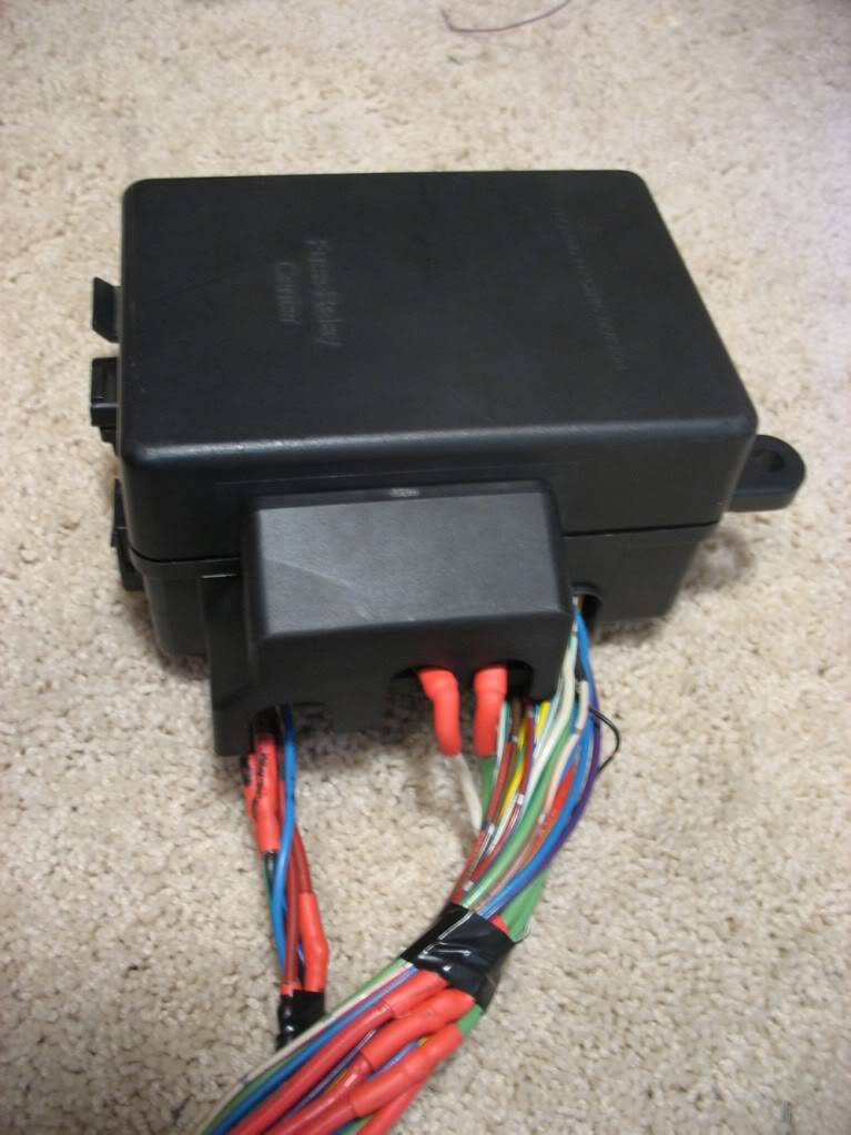
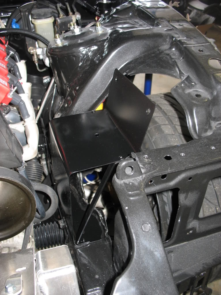
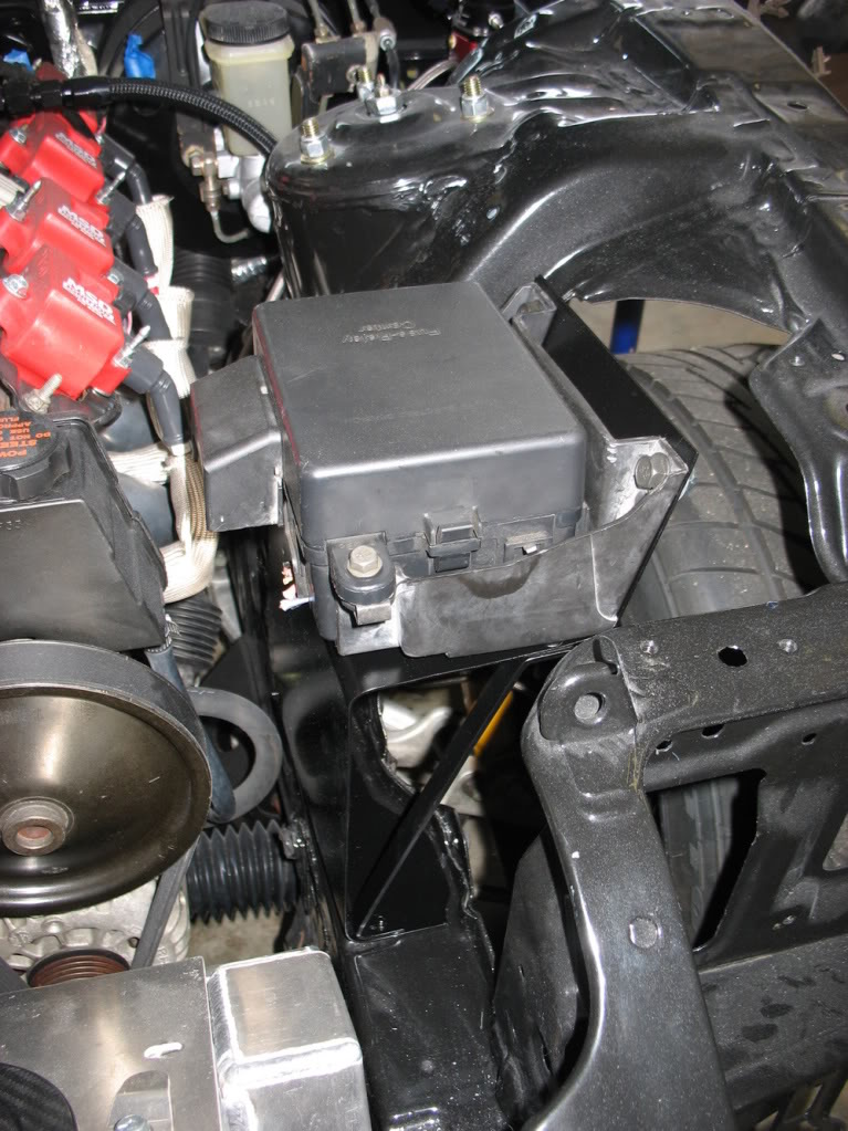
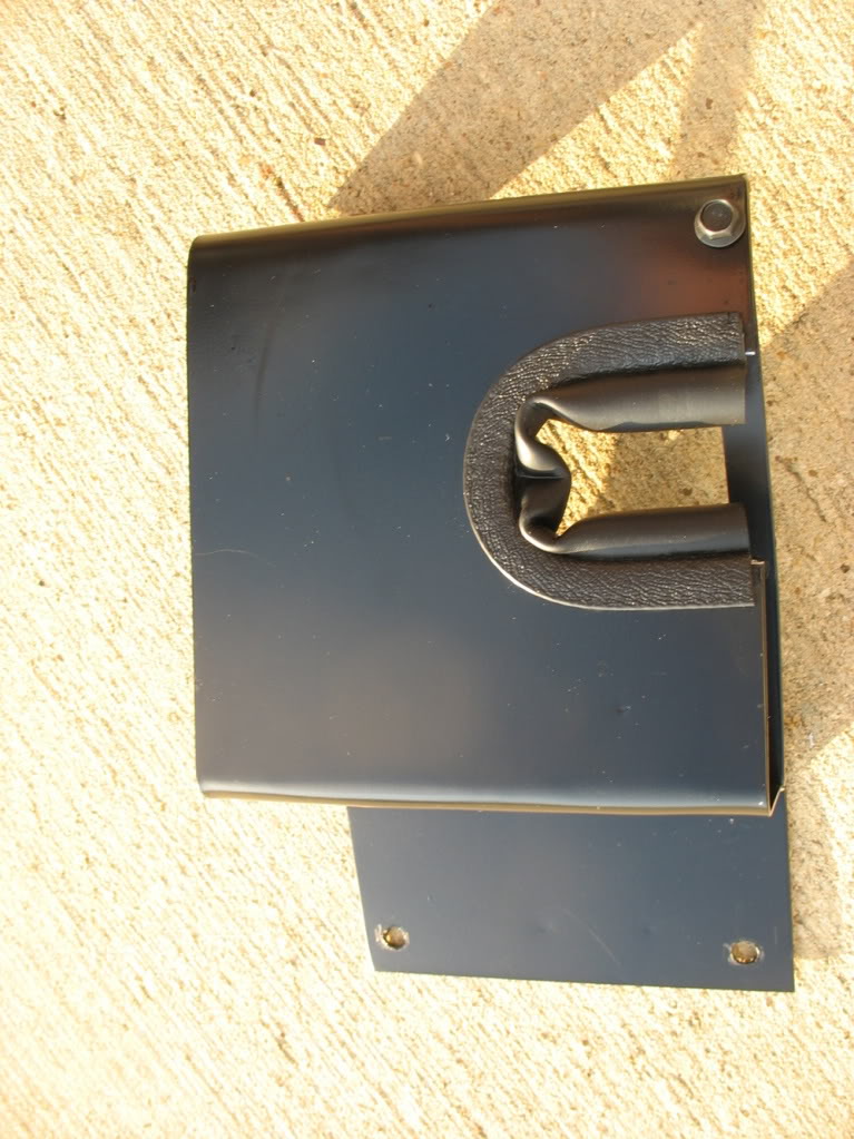
Next I fabricated the bracket I've had in mind for positioning the box in my engine bay:
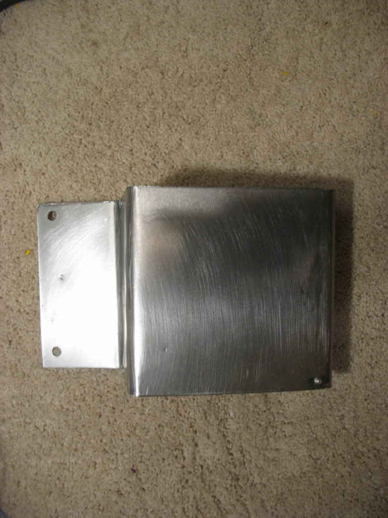
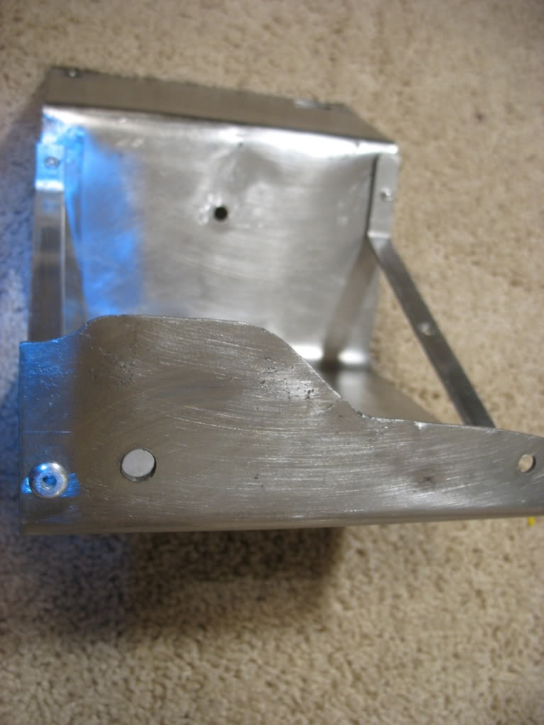
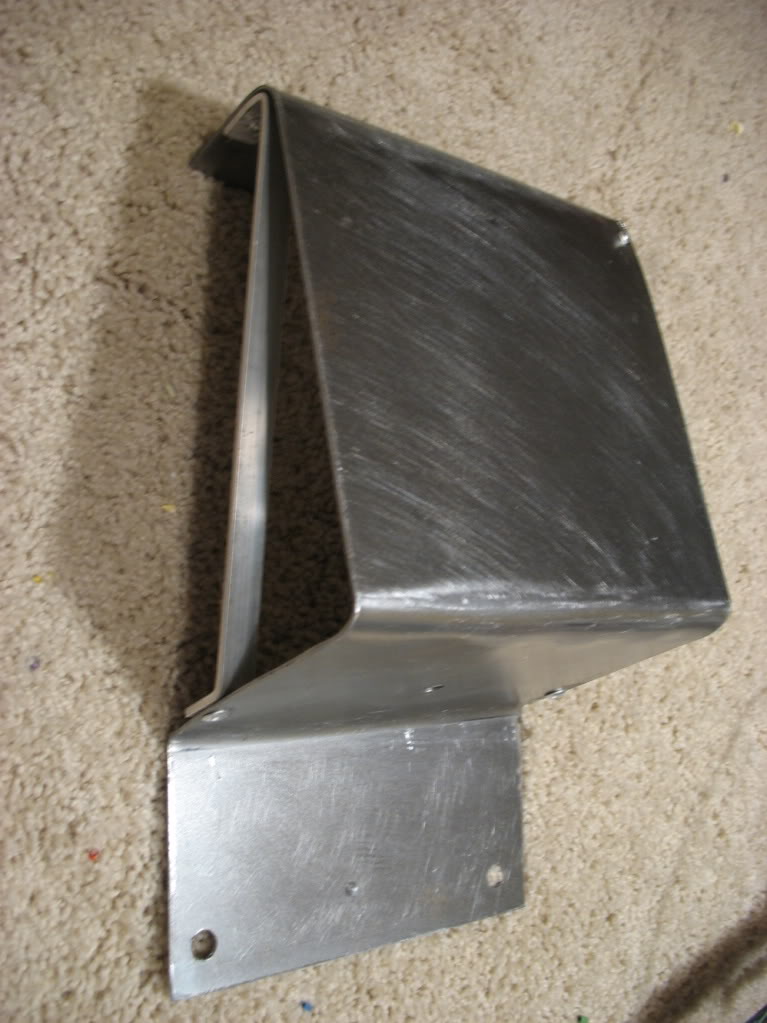
It was designed to fit very close to the stock fuse box location. I made it from mild steel using my press, pieces of bar
stock, and elbow grease since I didn't have access to a brake.
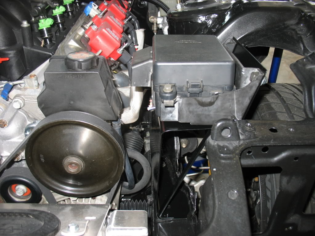
After painting it I decided to take some pictures of it and a dummy fuse box mocked up:
lately that has kept me from working on the rex for almost a month.
Finished up my fuse box:
Next I fabricated the bracket I've had in mind for positioning the box in my engine bay:
It was designed to fit very close to the stock fuse box location. I made it from mild steel using my press, pieces of bar
stock, and elbow grease since I didn't have access to a brake.
After painting it I decided to take some pictures of it and a dummy fuse box mocked up:
Thread Starter
Joined: Apr 2009
Posts: 381
Likes: 27
From: Starkville, MS
At this point I realized the wire's natural exit from the front harness really made it easiest to wrap around the backside
of the bracket, so I modified it:
After getting my fuse box placement finalized I finally finished my front harness:
Comparison pictures of what my front harness started out looking like can be found here:
http://www.norotors.com/index.php?topic=2468.0
Who knows... I might give some of y'all an idea on where to get started since I still hear the question "what can I delete" pretty often
Thread Starter
Joined: Apr 2009
Posts: 381
Likes: 27
From: Starkville, MS
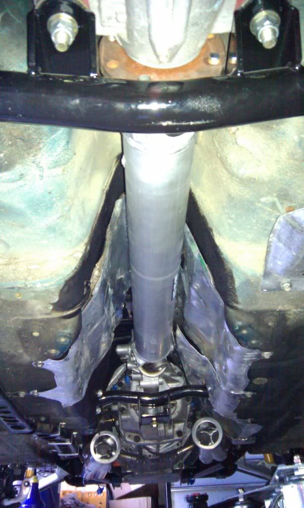
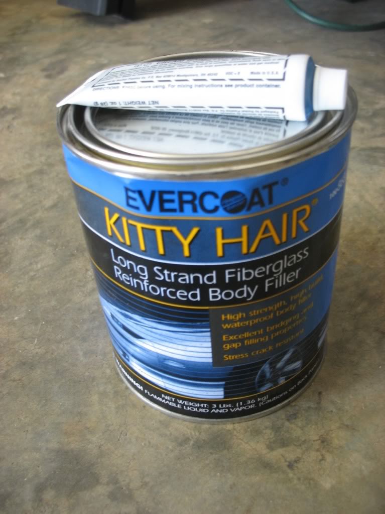
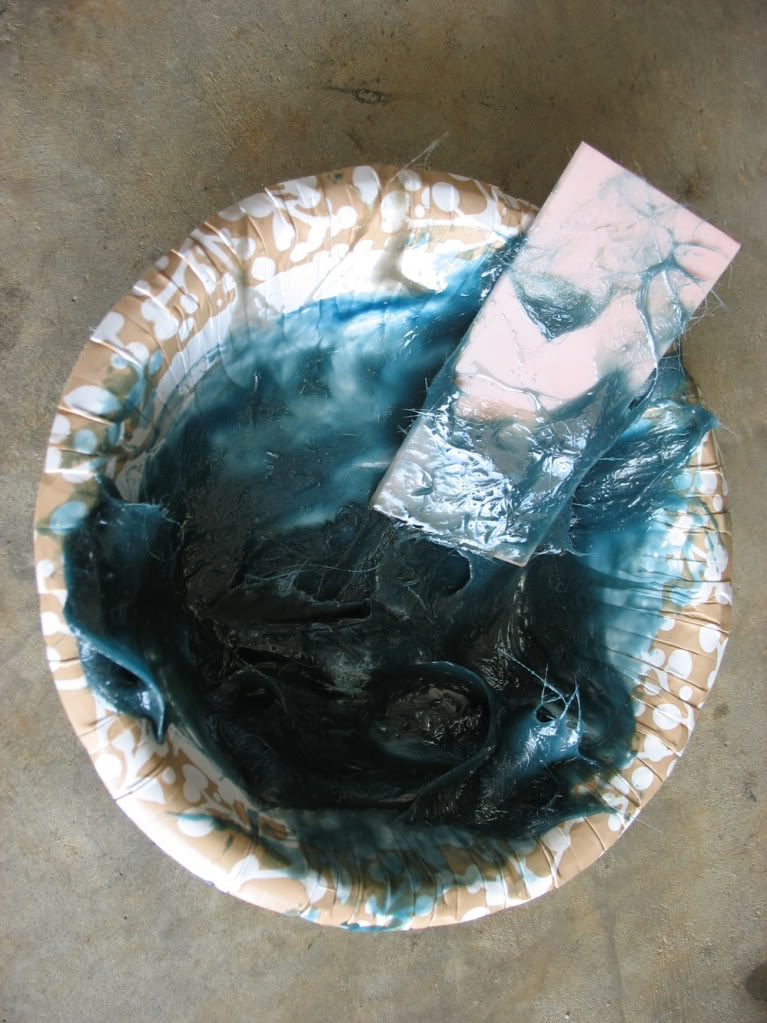
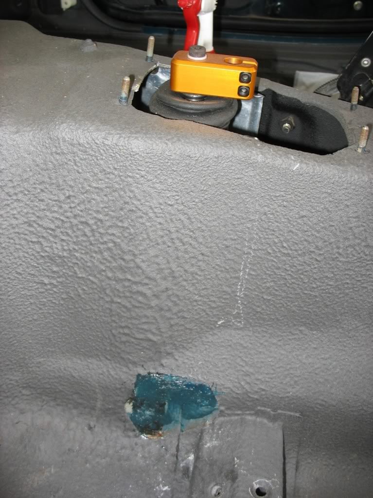
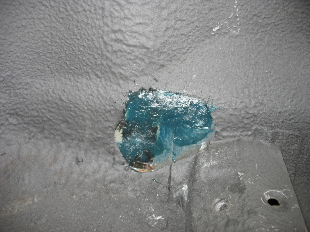
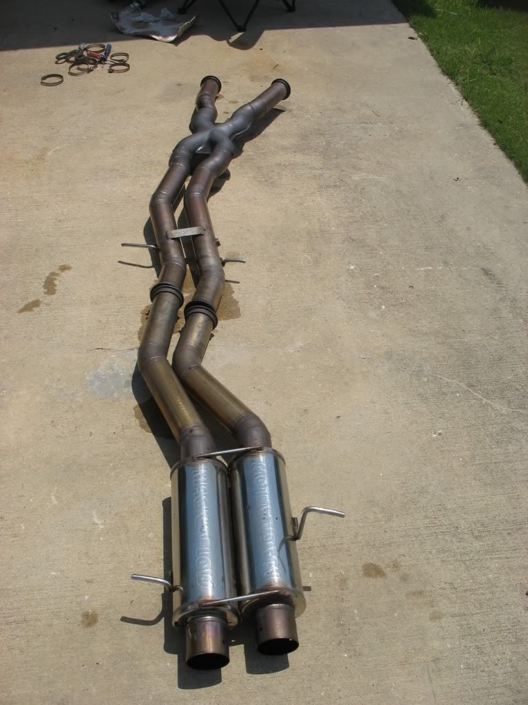
I've also recently acquired Kevin Doe's old 3" dual exhaust. As part of its install I removed my samberg trans brace and
kitty haired up the mounting holes in my trans tunnel. I've never used kitty hair, but it seems pretty stout and I hear it
has good hole filling properties
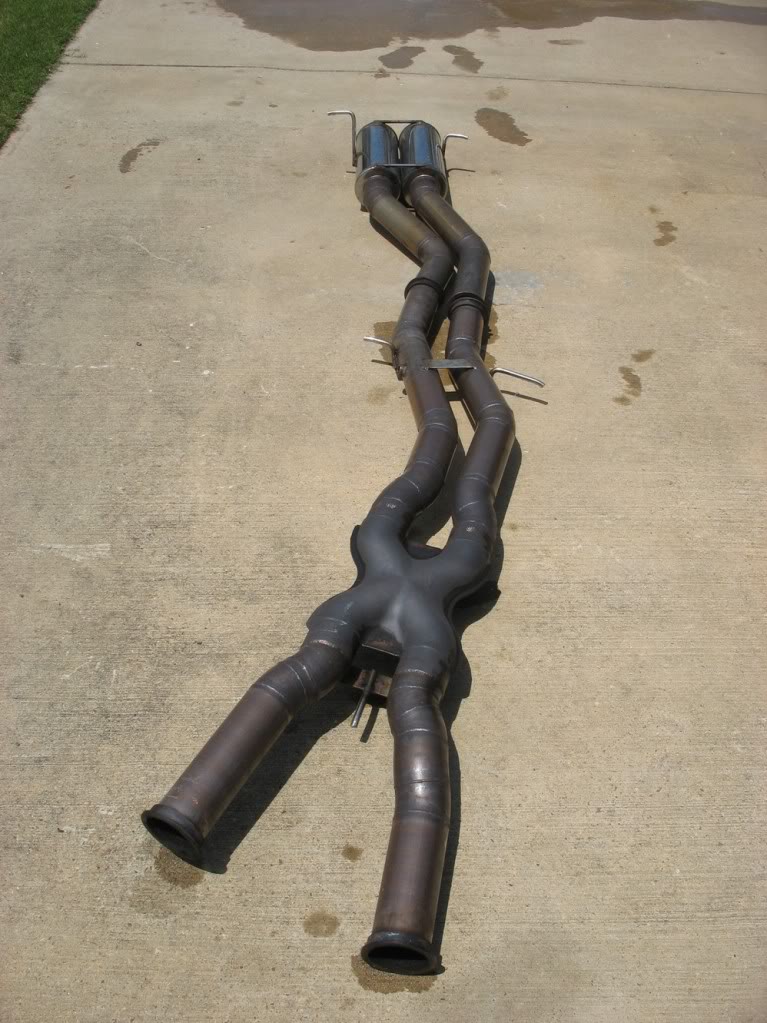
Speaking of the exhaust, here's a couple of pics after cleaning it up a little bit:
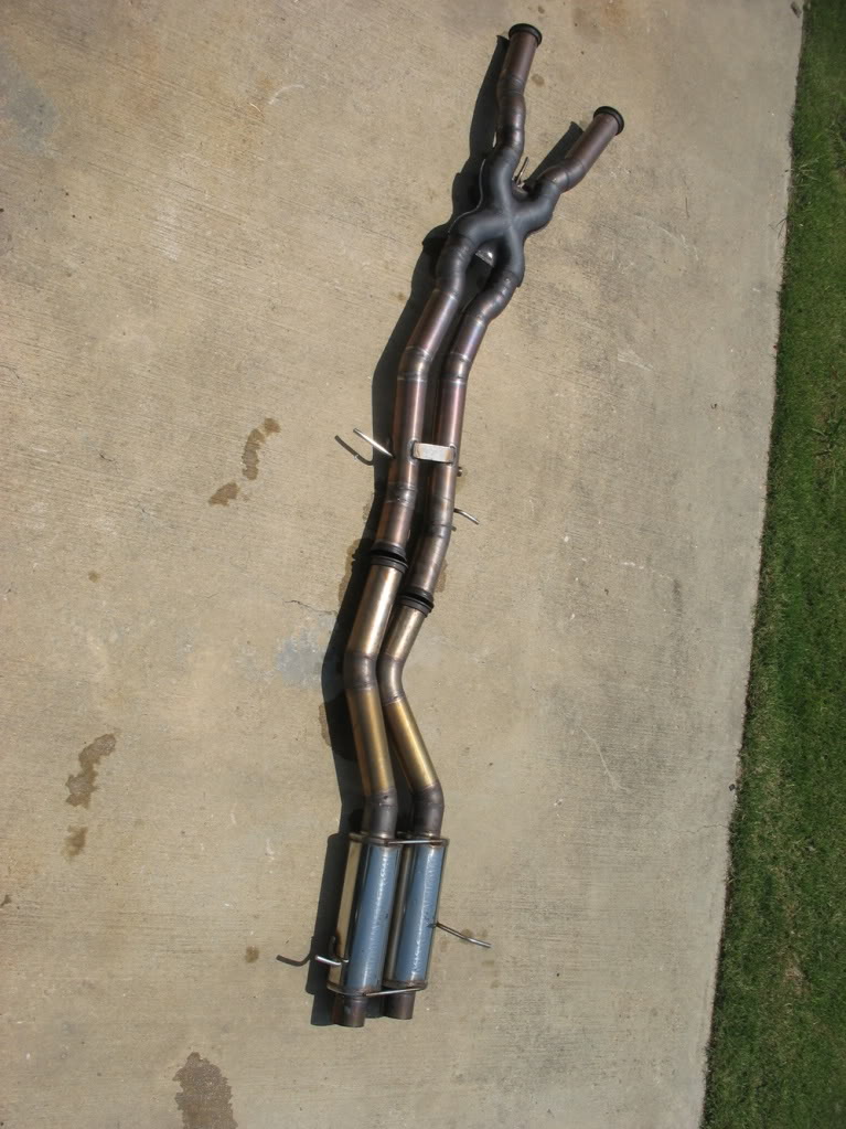
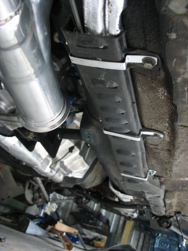
However, if you'll step back into the past (before I unwrapped it) you can see the problems I had during the initial mock up
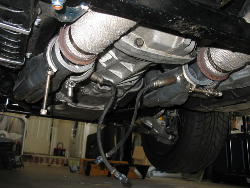
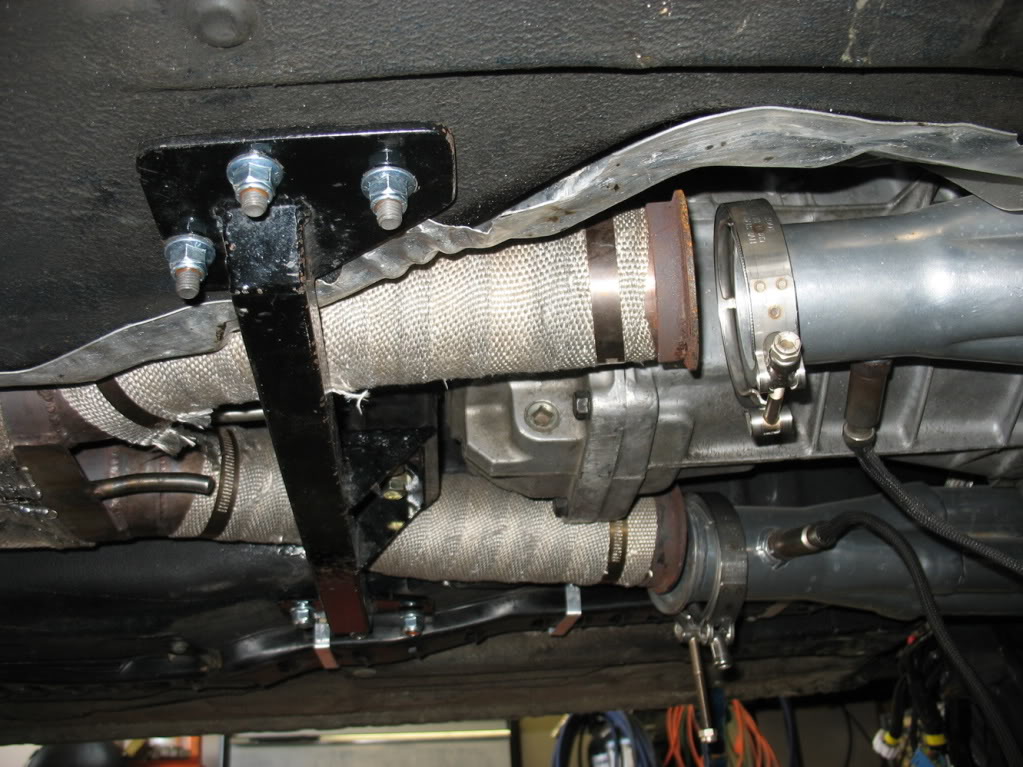
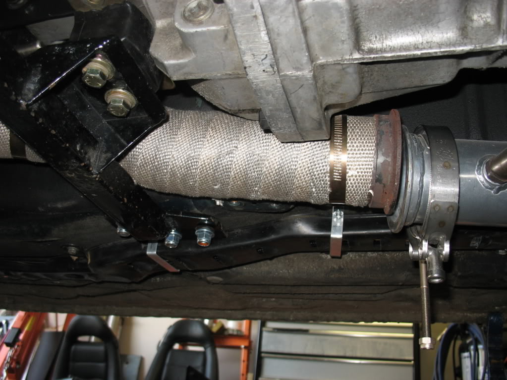
The last pic shows the biggest problem. The drivers side exhaust pipe sits on the transmission brace and supports the trans
above making it so the trans brace can not connect to the trans while the exhaust pipe is in-between it. Needless to say I
will have to do some modifications before the final install. It's not Kevin's fault at all though. This exhaust was built
for his car that uses a custom engine and diff subframe. It's no wonder it was not a plug and play fit on my car.
kitty haired up the mounting holes in my trans tunnel. I've never used kitty hair, but it seems pretty stout and I hear it
has good hole filling properties
Speaking of the exhaust, here's a couple of pics after cleaning it up a little bit:
However, if you'll step back into the past (before I unwrapped it) you can see the problems I had during the initial mock up
The last pic shows the biggest problem. The drivers side exhaust pipe sits on the transmission brace and supports the trans
above making it so the trans brace can not connect to the trans while the exhaust pipe is in-between it. Needless to say I
will have to do some modifications before the final install. It's not Kevin's fault at all though. This exhaust was built
for his car that uses a custom engine and diff subframe. It's no wonder it was not a plug and play fit on my car.
Thread Starter
Joined: Apr 2009
Posts: 381
Likes: 27
From: Starkville, MS
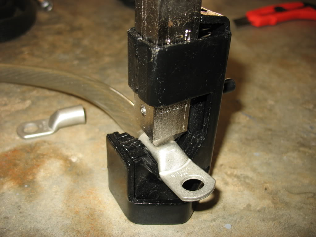
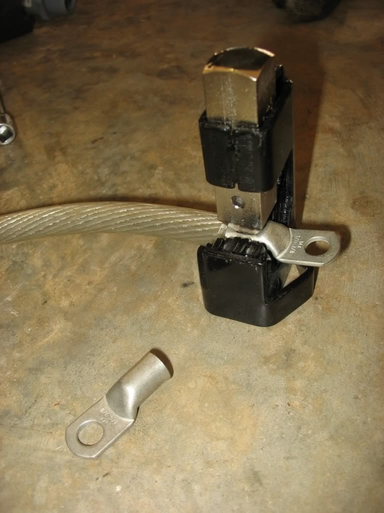
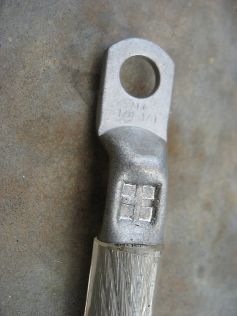
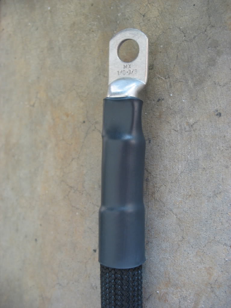
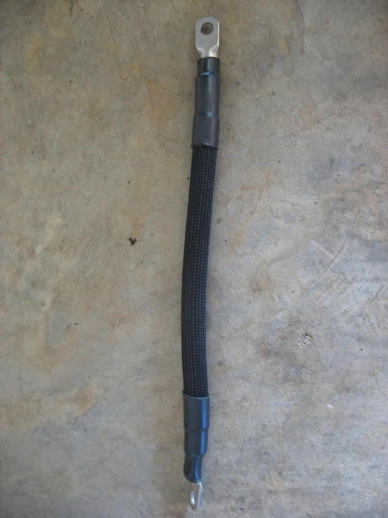
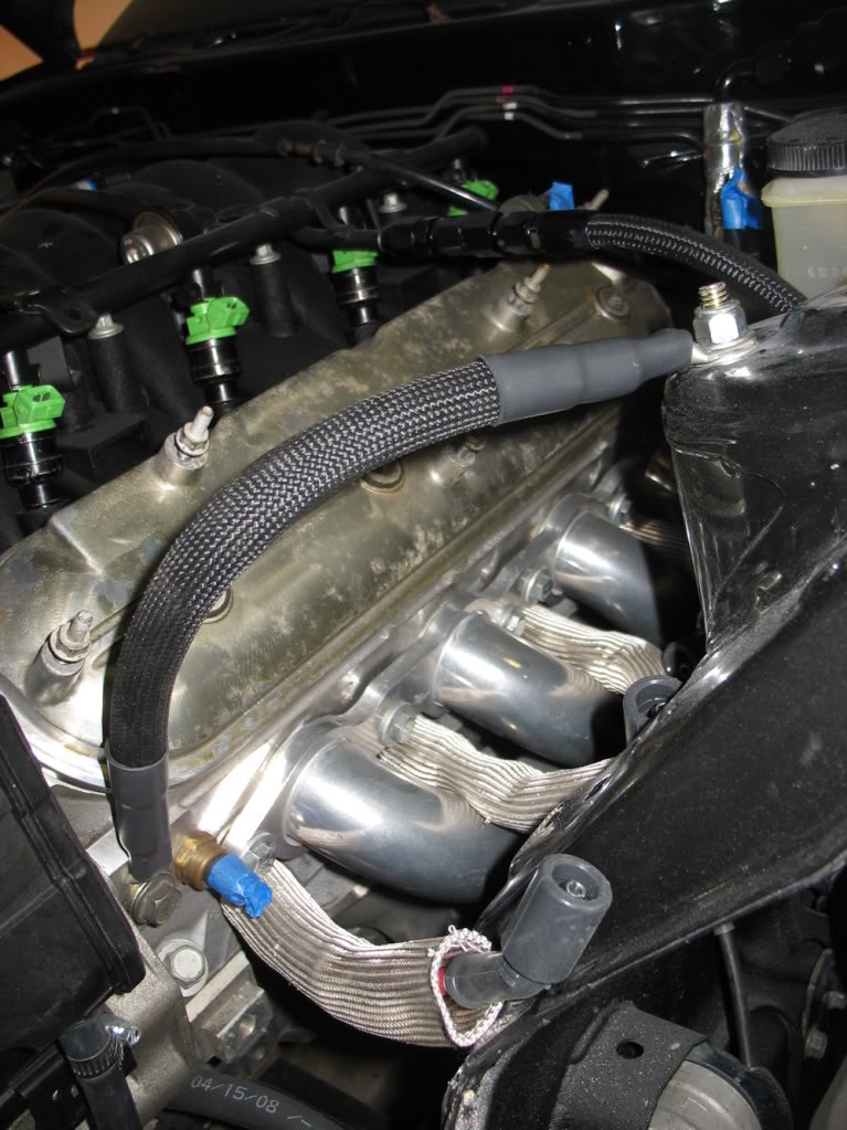
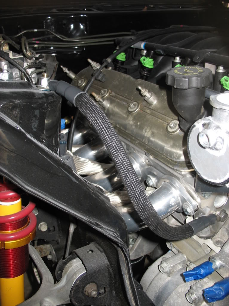
Also decided to do a little power routing starting with ground cables.
Finally, I modified my rear bin for my battery and PCM. I also make some repairs with fiberglass because my bin had a
hairline crack around the passenger bin lid.
That’s it for now
Lane
Finally, I modified my rear bin for my battery and PCM. I also make some repairs with fiberglass because my bin had a
hairline crack around the passenger bin lid.
That’s it for now
Lane
Thread Starter
Joined: Apr 2009
Posts: 381
Likes: 27
From: Starkville, MS
Here's what I've been up to for the past two weekends:
After giving it some thought, I decided to be on the safe side and do the second half of my lizard skin transformation. Last
summer I did two coats of lizard skin - sound control. Since then I've gone back and forth on what to do for insulating the
transmission tunnel. In the end I bought a gallon of Lizard Skin - Ceramic Insulation and top coated my sound control coat
(which it's designed to do). 1 gallon was enough to make two quick passes over the firewall, floorpan, and trans tunnel. I
felt like it was just enough:

This stuff has the consistency of marshmallow fluff.
Pretty much still stripped since last summer, so there wasn't much to do to prep except mask
Done and drying
While the ceramic insulation was drying I decided to do Danzan's self exciting voltage regulator alternator mod. It was
pretty straight forward. The only thing I fought with for a minute was the soldered connection terminal on the voltage
regulator to alternator connection. The alternator side of the connection is actually a "loop" (connection is circled in the
pics below) that the voltage regulator slides into, then the connection is soldered. I just thought it was two legs soldered
together, so I heated up the connection and tried to pull the old regulator off. It wasn't until I closely inspected it that
I saw it was a loop and the the regulator had to drop out from under it to clear the loop. Maybe pictures will make it
easier to visualize
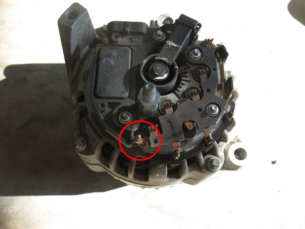
Alternator with stock voltage regulator
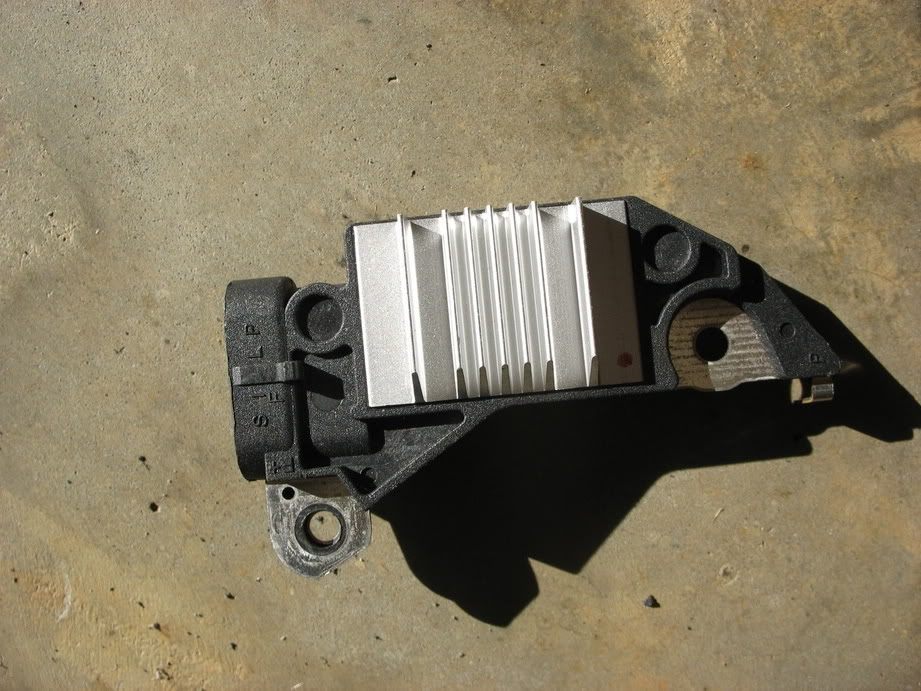
Self exciting voltage regulator
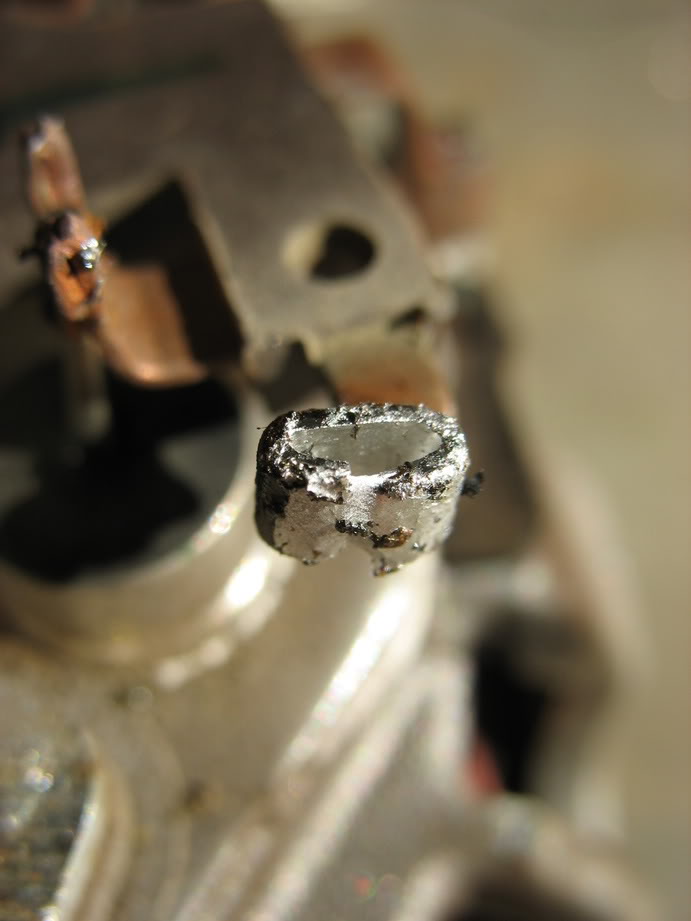
Alternator to voltage regulator connection loop (desoldered)
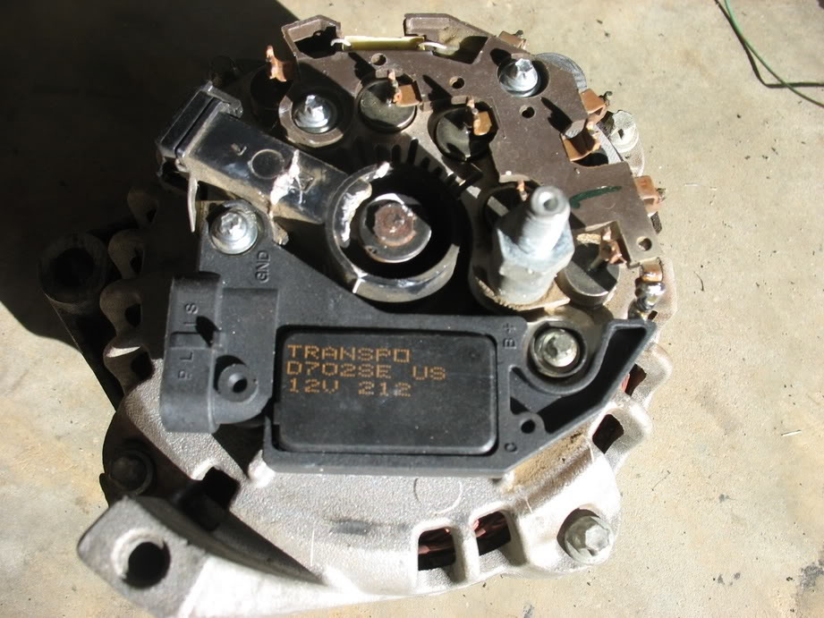
Alternator with self exciting regulator installed
After pulling out my pedals to spray my interior, I realized how crappy they look. I'd like to say everyone's pedals look
this bad, but I had the bright idea to use naval jelly on them last summer to try and clean the rust up, which is why they
have lovely white splotches on them AND rust. Well, in the interest of keeping the in good shape I decided to rebuild them,
starting with a good bead blasting. Here are the before pictures:
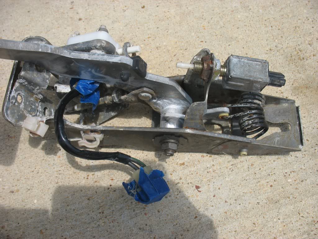
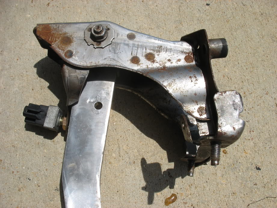
The after pictures will come with my next update. I'm not messing with the actual pedals, but mainly just the steel housings
After giving it some thought, I decided to be on the safe side and do the second half of my lizard skin transformation. Last
summer I did two coats of lizard skin - sound control. Since then I've gone back and forth on what to do for insulating the
transmission tunnel. In the end I bought a gallon of Lizard Skin - Ceramic Insulation and top coated my sound control coat
(which it's designed to do). 1 gallon was enough to make two quick passes over the firewall, floorpan, and trans tunnel. I
felt like it was just enough:
This stuff has the consistency of marshmallow fluff.
Pretty much still stripped since last summer, so there wasn't much to do to prep except mask
Done and drying
While the ceramic insulation was drying I decided to do Danzan's self exciting voltage regulator alternator mod. It was
pretty straight forward. The only thing I fought with for a minute was the soldered connection terminal on the voltage
regulator to alternator connection. The alternator side of the connection is actually a "loop" (connection is circled in the
pics below) that the voltage regulator slides into, then the connection is soldered. I just thought it was two legs soldered
together, so I heated up the connection and tried to pull the old regulator off. It wasn't until I closely inspected it that
I saw it was a loop and the the regulator had to drop out from under it to clear the loop. Maybe pictures will make it
easier to visualize
Alternator with stock voltage regulator
Self exciting voltage regulator
Alternator to voltage regulator connection loop (desoldered)
Alternator with self exciting regulator installed
After pulling out my pedals to spray my interior, I realized how crappy they look. I'd like to say everyone's pedals look
this bad, but I had the bright idea to use naval jelly on them last summer to try and clean the rust up, which is why they
have lovely white splotches on them AND rust. Well, in the interest of keeping the in good shape I decided to rebuild them,
starting with a good bead blasting. Here are the before pictures:
The after pictures will come with my next update. I'm not messing with the actual pedals, but mainly just the steel housings
Thread Starter
Joined: Apr 2009
Posts: 381
Likes: 27
From: Starkville, MS
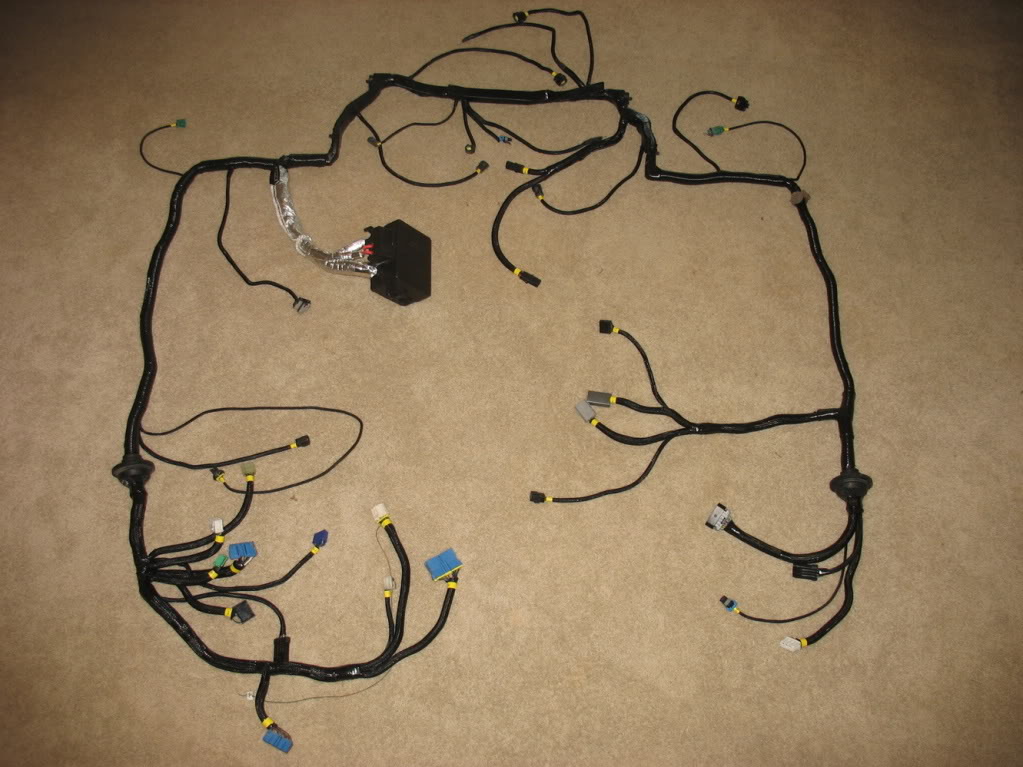
How about some wiring crazyness????
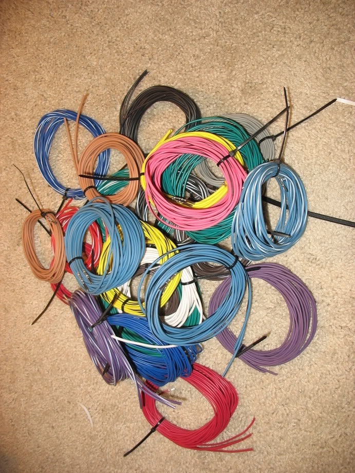
Thanks to Pez, I have all the color coded wire I need to properly extend and finish my engine harness
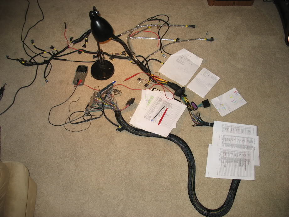
A rare look behind the scenes. Finished and toning out the harness to make sure I didn't make any mistakes
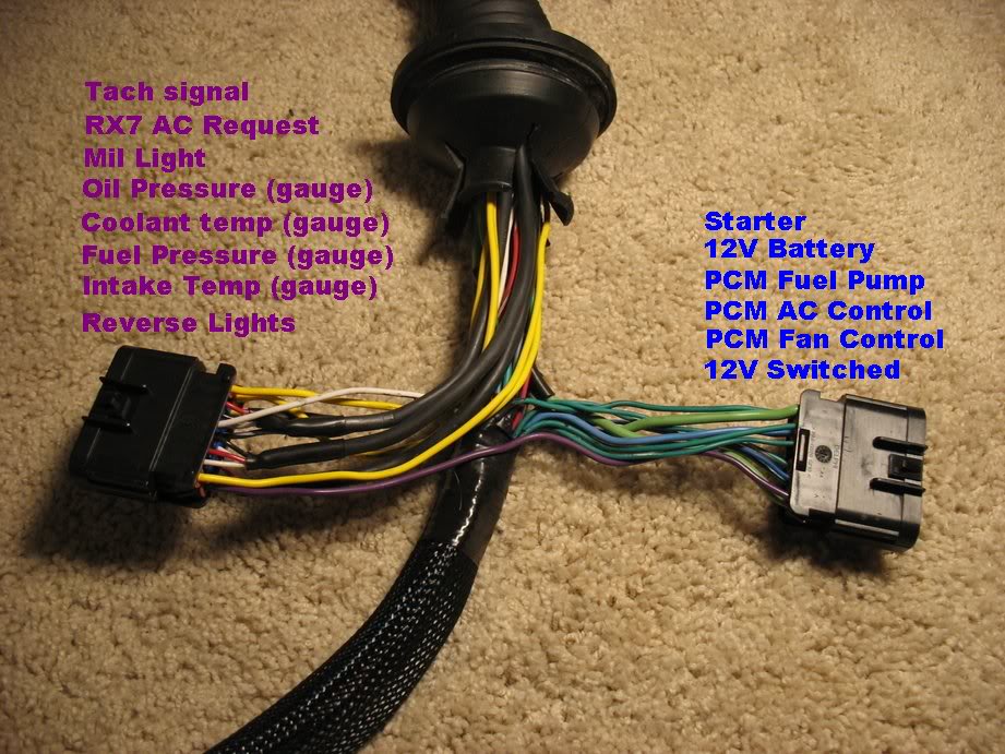
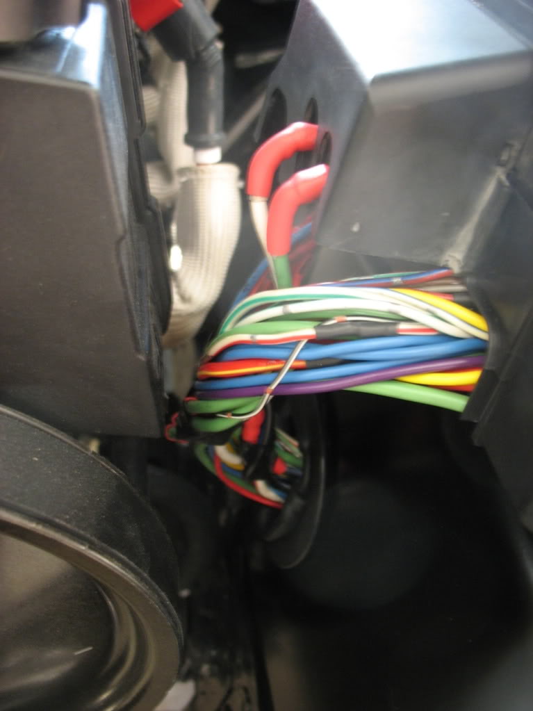
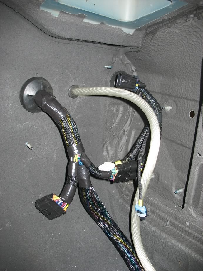
Here's something I'm particularly proud of. These two connectors are built into the harness right inside the firewall. The
functions for each connector is listed in the picture above. It just makes it so I can pull the harness out easily by
unclipping connectors rather than having to cut or desolder wires.
After I finished my engine harness I started installing it and populating my interior
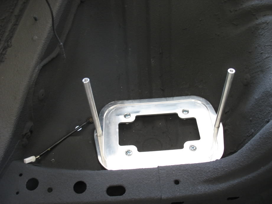
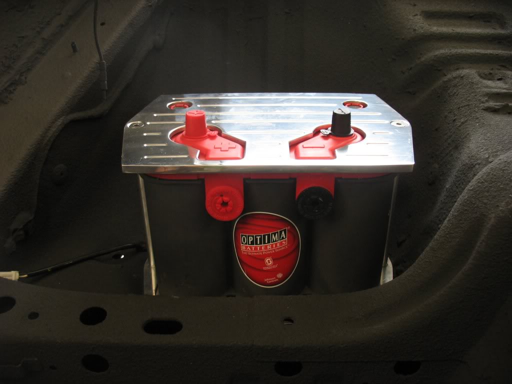
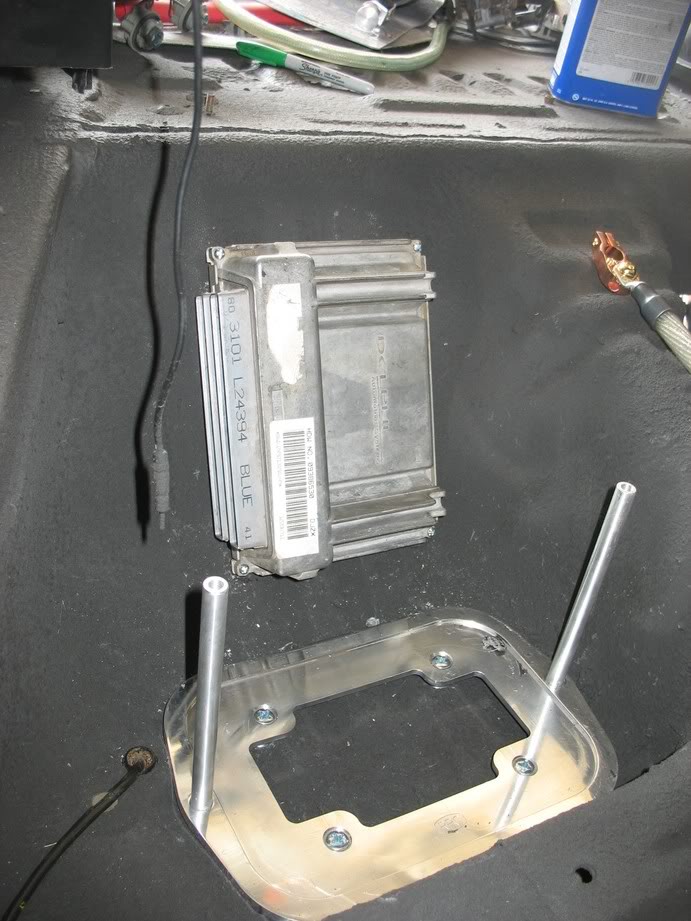
Mocking up my battery holder under the passenger bin
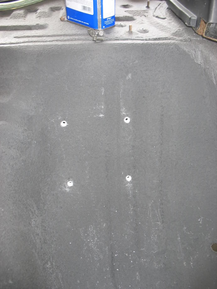
Fastened with nutserts
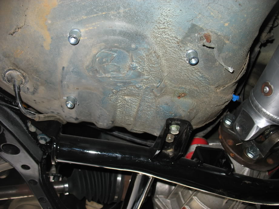
More nutserts on the driver's side?
:yay:
Thanks to Pez, I have all the color coded wire I need to properly extend and finish my engine harness
A rare look behind the scenes. Finished and toning out the harness to make sure I didn't make any mistakes
Here's something I'm particularly proud of. These two connectors are built into the harness right inside the firewall. The
functions for each connector is listed in the picture above. It just makes it so I can pull the harness out easily by
unclipping connectors rather than having to cut or desolder wires.
After I finished my engine harness I started installing it and populating my interior
Mocking up my battery holder under the passenger bin
Fastened with nutserts
More nutserts on the driver's side?
:yay:
Thread Starter
Joined: Apr 2009
Posts: 381
Likes: 27
From: Starkville, MS
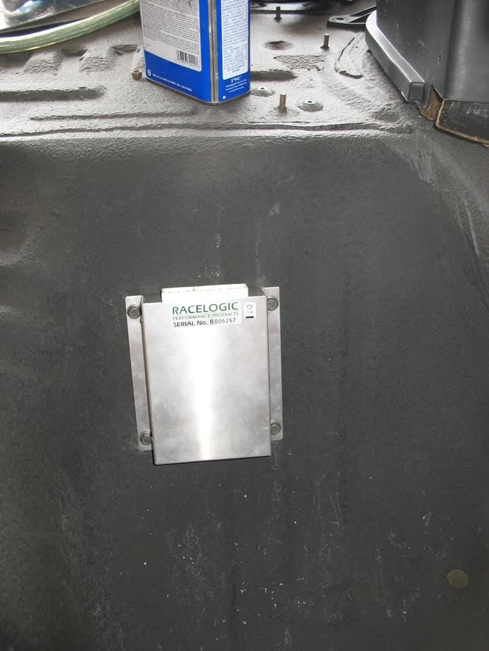
Loose install of my PCM (waiting on more nutserts and proper bolts)
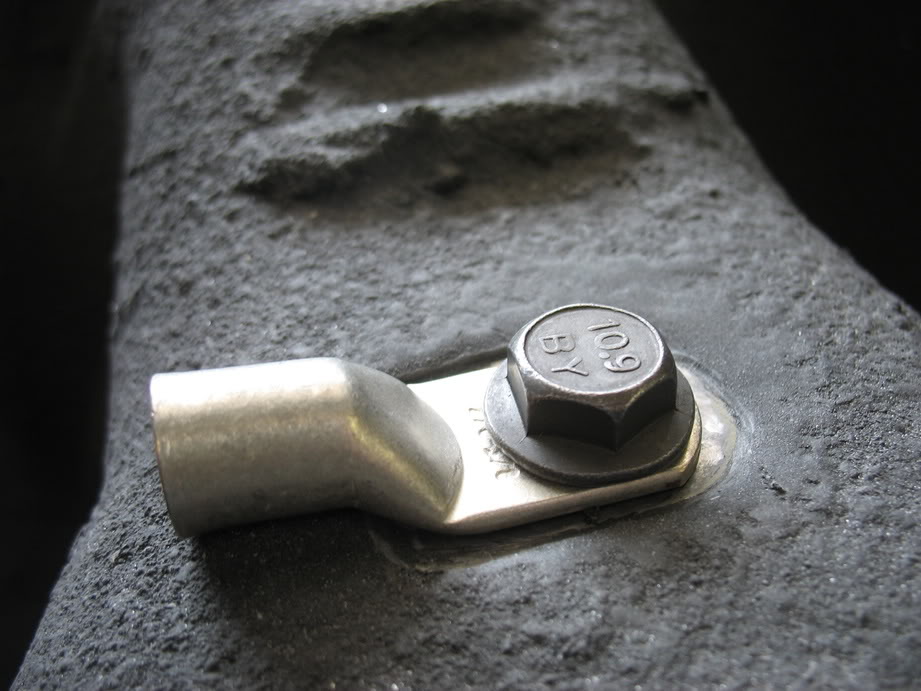
Cutting out a nice little bare metal pad for my ground terminal to sit
How's that for short?
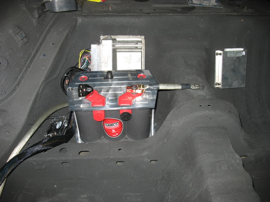
Mounted for now
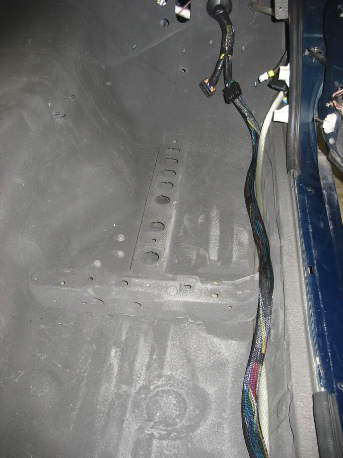
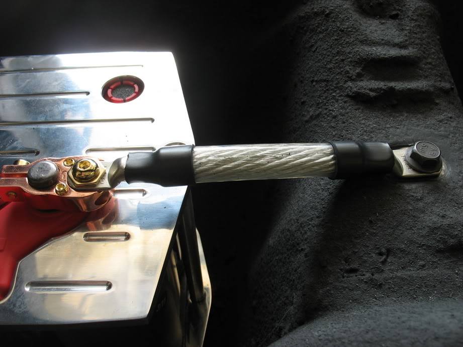
Routing
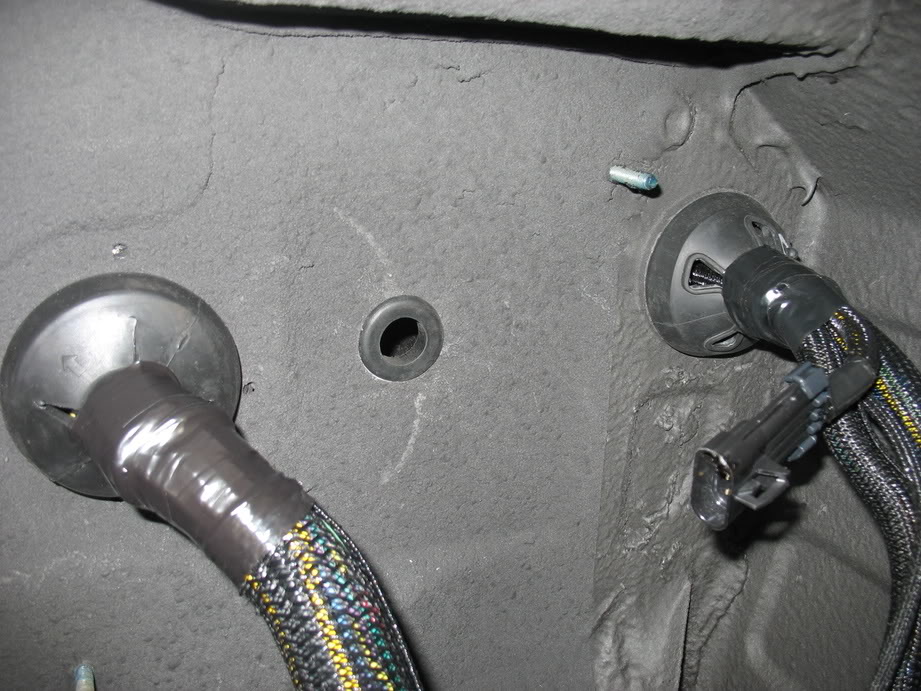
Hooray for grommets!
That's it for this week
Lane
Cutting out a nice little bare metal pad for my ground terminal to sit
How's that for short?
Mounted for now
Routing
Hooray for grommets!
That's it for this week
Lane
Thread Starter
Joined: Apr 2009
Posts: 381
Likes: 27
From: Starkville, MS
2nd update in two days??? Yes sir!
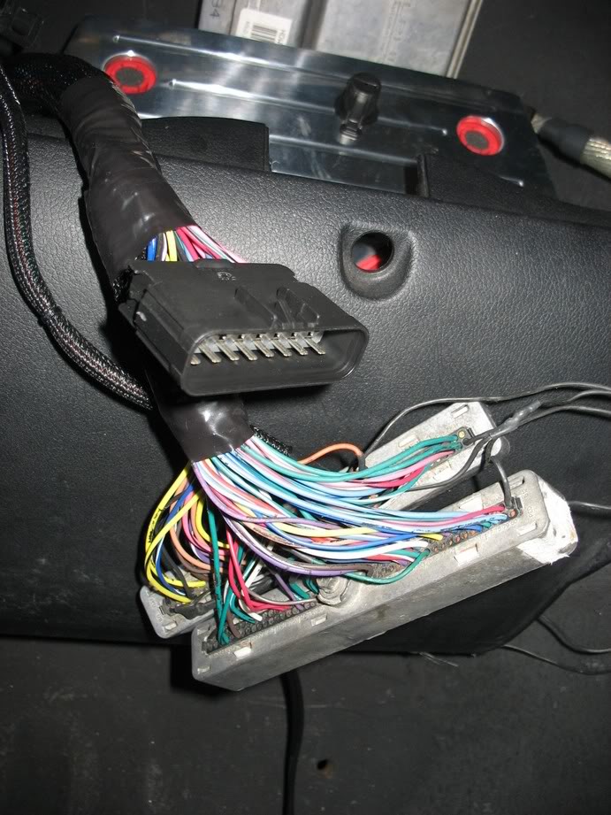
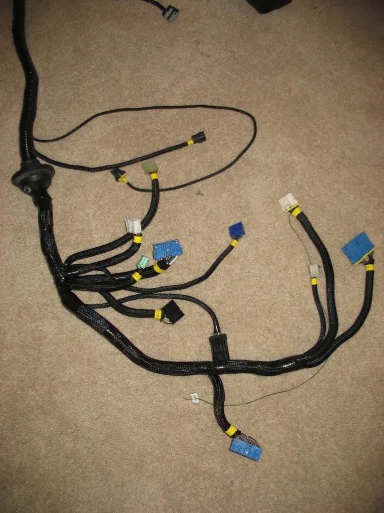
Something I forgot to mention yesterday is that I added a injector signal 'break' connector into my engine harness. This was
simply to make my racelogic TC plug-and-play. It's 16 pins and contains the engine side and pcm side for each injector.
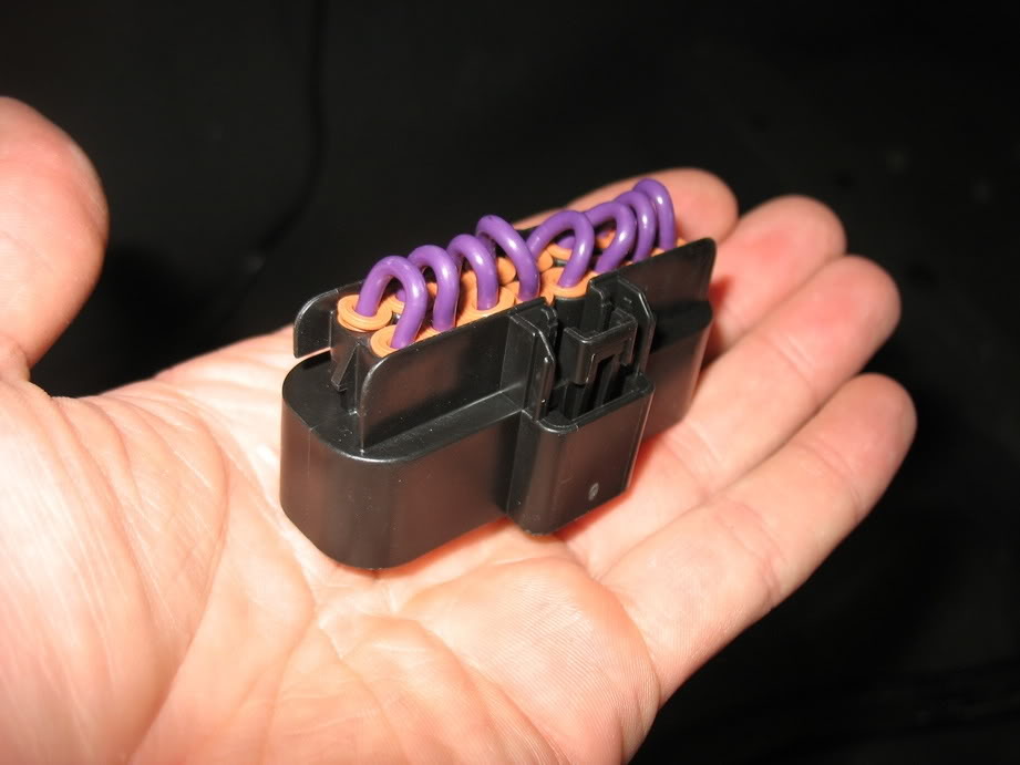
While I was at it I made a shorting plug to restore the harness to it's factory config if I ever needed to remove my TC
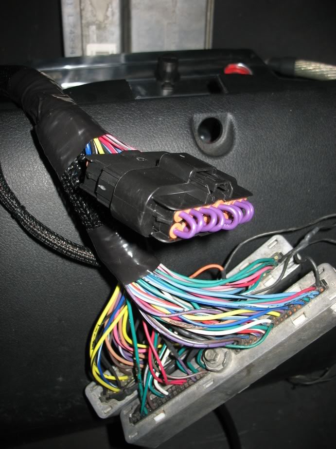
Shorting plug installed.
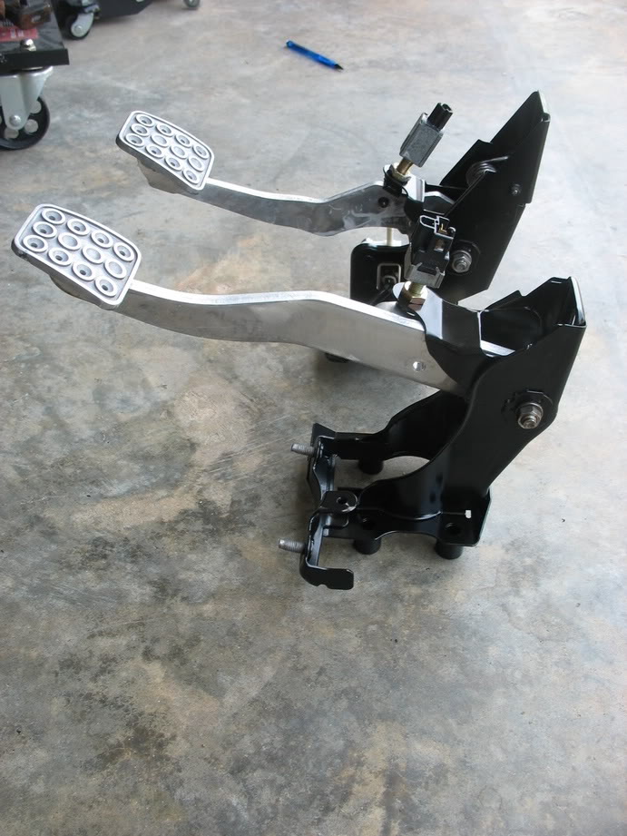
Ta da! Pedals after rebuild
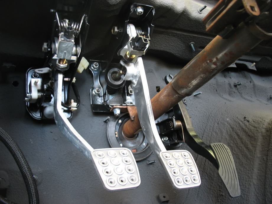
Installed with blingin new hardware
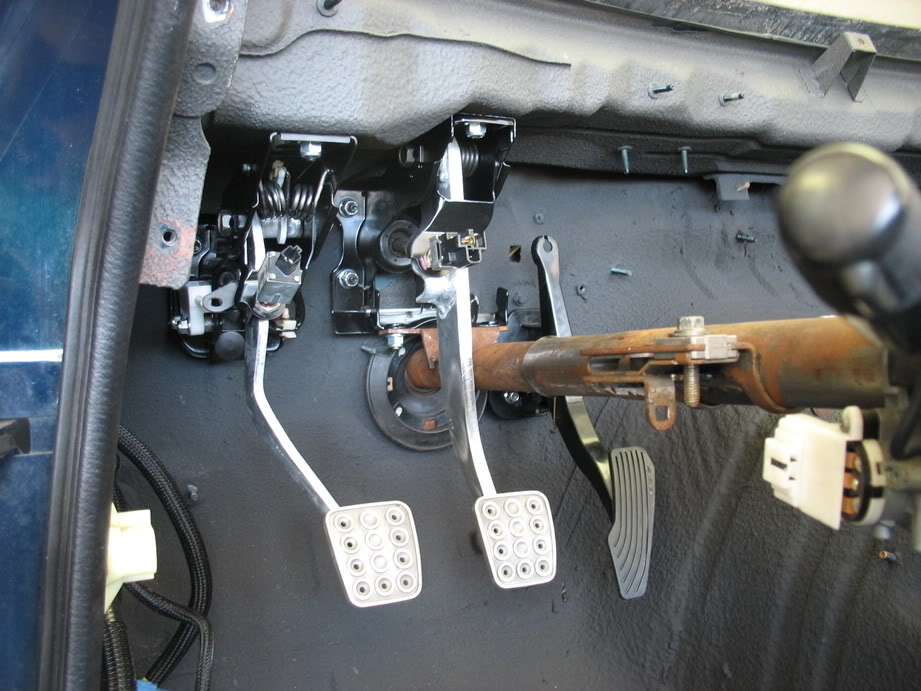
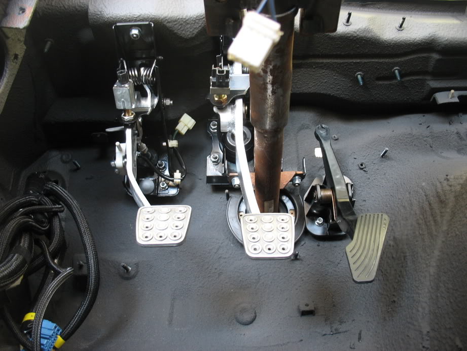
Now I'll have to do something about that stupid rusty steering shaft :
Lane
Something I forgot to mention yesterday is that I added a injector signal 'break' connector into my engine harness. This was
simply to make my racelogic TC plug-and-play. It's 16 pins and contains the engine side and pcm side for each injector.
While I was at it I made a shorting plug to restore the harness to it's factory config if I ever needed to remove my TC
Shorting plug installed.
Ta da! Pedals after rebuild
Installed with blingin new hardware
Now I'll have to do something about that stupid rusty steering shaft :
Lane