
Interested in comments on tubular manifold design

Thread Starter

Joined: May 2005
Posts: 729
Likes: 19
From: LBC, CA
Interested in comments on tubular manifold design
I was inspired by jdmfantasy's killer turbo exhaust manifold design/fab thread so I'll share the result of my Solidworks brainteaser also.
For now, here are some shots of a manifold for my FC. It's based on using 2.0" 304 SS piping, which is overkill for my T4 turbo, but it seems to fit. Comments encouraged.
For now, here are some shots of a manifold for my FC. It's based on using 2.0" 304 SS piping, which is overkill for my T4 turbo, but it seems to fit. Comments encouraged.

I would change the wastegate routing to come off the primary runners at a tighter angle. Wont make a huge difference, but you will be able to control boost better. Overall, good design.


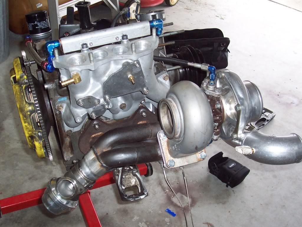

You would think so, but so far it's held up ok actually. It is the older Tial 44mm design before they switched to the smaller MVR design which supposedly doesn't dissipate heat as well (hence the added coolant ports). The gate is not physically touching anything. There's a couple centimeters clearance.
Thread Starter
Joined: May 2005
Posts: 729
Likes: 19
From: LBC, CA
What connector is threaded into your compressor exit? Presumably it's a pressure port, just looks odd to me.
Trending Topics
Not sure what you mean by tighter angle, but at least the wastegate plumbing is at the outer edge of the bend. Tight space at the front subframe and framerails is limiting the wastegate routing.
Agreed, and the fabricator knows this, it's just difficult to model the firewall accurately to determine how much real estate is available. If he has the space, he'll merge the wastegate dump tube more tangential like your pics. Nice shots BTW.
What connector is threaded into your compressor exit? Presumably it's a pressure port, just looks odd to me.
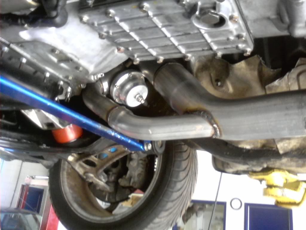
The angle of the wastegate outlet to downpipe actually requires more space than would be necessary with a low angle merge. The shortest path is always a straight line. Im guessing its a small flex section between the wastegate outlet and the downpipe, and thats where the merge should begin.
With fitment constraints you do have to make compromises with the routing of the wastegate runners and recirc pipe. You'll just have to do the best you can.
They are 1/4" brass barbed fittings, covered with masking tape in that pic.
Originally Posted by cone_crushr
What connector is threaded into your compressor exit? Presumably it's a pressure port, just looks odd to me.

Thread
Thread Starter
Forum
Replies
Last Post
rx8volks
Canadian Forum
0
Sep 1, 2015 11:02 PM
rx8volks
Canadian Forum
0
Sep 1, 2015 10:46 PM
82streetracer
1st Generation Specific (1979-1985)
7
Aug 23, 2015 09:28 AM