
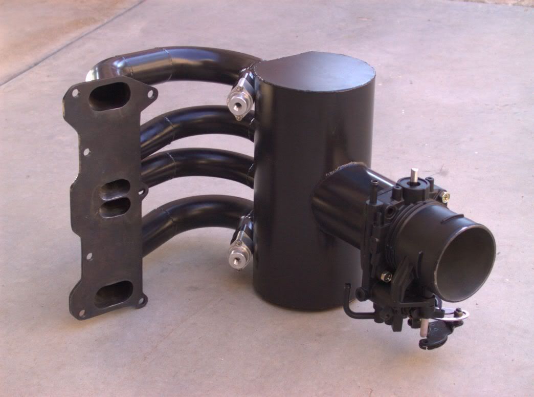
intake manifold pics for my single FD project...


Thread Starter
Rotary Freak
Joined: Dec 2001
Posts: 2,402
Likes: 0
From: chandler, AZ
Originally Posted by crispeed
It's gonna leak under boost. Even the factory intakes are prone to leaking on the primary ports at high boost. I always use 3/4 inch to 1 inch 6061 to help with that problem.
Last edited by 2a+RoN; Mar 13, 2006 at 09:37 AM.
multipersonality disorder
Joined: Feb 2002
Posts: 5,656
Likes: 0
From: so. cal
Originally Posted by crispeed
It's gonna leak under boost. Even the factory intakes are prone to leaking on the primary ports at high boost. I always use 3/4 inch to 1 inch 6061 to help with that problem.
1" flanges on an intake manifold?

Banned. I got OWNED!!!
Joined: Mar 2001
Posts: 2,306
Likes: 1
From: lebanon
Steel is MUCH more rigid than very weak Alloy, combined with the pipes stiffness to the plenum and if its flat already it will take a hell of a force to distort it (100+psi).
I doubt very much you will have any problems at all
P.S. Lots of people here use M.S. *of similar diminesions* to construct intake manifolds with no issues @ 35psi boost pressures. You will find it far better than welded alloy as it wont crack in service as its much stronger against fatigue, good choice mate 6061 or anything else of heat treated grade is not that after its welded either  but the extra thickness does help.
I doubt very much you will have any problems at all
P.S. Lots of people here use M.S. *of similar diminesions* to construct intake manifolds with no issues @ 35psi boost pressures. You will find it far better than welded alloy as it wont crack in service as its much stronger against fatigue, good choice mate
6061 or anything else of heat treated grade is not that after its welded either but the extra thickness does help.

adiabaticly inefficient
Joined: Aug 2001
Posts: 386
Likes: 0
From: nw houston,TX or w. hollywood,CA
is there any taper in those runners.i just always figured u would want some sort of taper in the runners to add a bit of velocity and or cut down on pumping losses<------not an expert tho
Thread Starter
Rotary Freak
Joined: Dec 2001
Posts: 2,402
Likes: 0
From: chandler, AZ
Originally Posted by T04Eneedy
is there any taper in those runners.i just always figured u would want some sort of taper in the runners to add a bit of velocity and or cut down on pumping losses<------not an expert tho
i really dont think you would need a flange thicker then 1/2". whats the length of your runners? sorry im asking so many questions im just so interested and would like to start applying these dimensions to my plans and modifly them a little bit... then its gonna be made of stainless
Thread Starter
Rotary Freak
Joined: Dec 2001
Posts: 2,402
Likes: 0
From: chandler, AZ
runners are 15". Like I said earlier, I think I would go w/ a little bit smaller diameter runners, it was kinda a bitch matching the runners to the ports, might make the engine a lil happier too. Good luck w/ your project.


Full Member
Joined: Feb 2005
Posts: 208
Likes: 0
From: florida
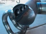
did you make that out of stainles steel its going to be very hot
i would have mounted the trottle body direct to that 3 inch pipe
look at mine
some more more
i would have mounted the trottle body direct to that 3 inch pipe
look at mine
some more more
Thread Starter
Rotary Freak
Joined: Dec 2001
Posts: 2,402
Likes: 0
From: chandler, AZ
Its made of mild steel. It only cost me ~$50 alltogether since I had scrap of everything except the u-bends.
Which 3" pipe? I assume you mean the plenum?
I almost wanna make another one now that I have so many things that I'd do differently..
Which 3" pipe? I assume you mean the plenum?
I almost wanna make another one now that I have so many things that I'd do differently..
Full Member
Joined: Feb 2005
Posts: 208
Likes: 0
From: florida
i wanted to make one similar like your with 1.5 aluminum bends from burnsstainless
i made the turbo manifold first and when i started building the intake manifold there was no room to clear runner #1
i might still come up with some thing
i think you also got a q45 tb???
i made the turbo manifold first and when i started building the intake manifold there was no room to clear runner #1
i might still come up with some thing
i think you also got a q45 tb???
Thread Starter
Rotary Freak
Joined: Dec 2001
Posts: 2,402
Likes: 0
From: chandler, AZ
its a secret...
Actually, I found something in the shop, i think a socket, that had a bit of a flare on it and it's od matched the id of the tube, then just pressed the tube onto it. Worked great.
Actually, I found something in the shop, i think a socket, that had a bit of a flare on it and it's od matched the id of the tube, then just pressed the tube onto it. Worked great.
Originally Posted by 2a+RoN
its a secret...
Actually, I found something in the shop, i think a socket, that had a bit of a flare on it and it's od matched the id of the tube, then just pressed the tube onto it. Worked great.
Actually, I found something in the shop, i think a socket, that had a bit of a flare on it and it's od matched the id of the tube, then just pressed the tube onto it. Worked great.
NICE, thats all i can say
