
intake air temp sensor


Full Member
Joined: Nov 2016
Posts: 102
Likes: 15
From: Edmonton
So is the consciences that a thermocouple is the best option? Is there a "best" thermistor to use in place of the OEM FD sensor? I currently have EGT's just on a gauge and one day will look into adding a 4-channel module and run 2 EGT and 2 AIT so I can properly log but in the meantime swapping out to the best thermistor would be easy. I don't mean to suggest a OEM replacement, swapping out a pig tail isn't a problem and I have a stand alone, but one that fits the oem location would be ideal. I didn't realize the oem one was so slow.
Thread Starter


Joined: Oct 2001
Posts: 6,279
Likes: 728
From: Florence, Alabama
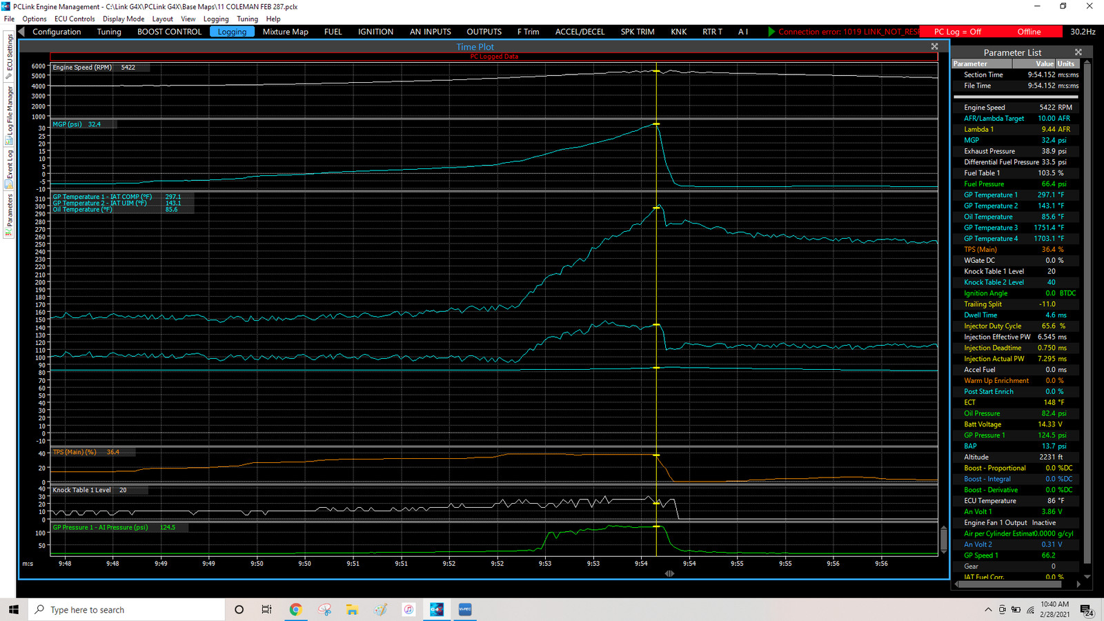
finally starting to get some comparative IAT data re thermocouple and thermistor sensors. here's a run i just did to 32.4 PSI with my EFR 9180. this wasn't a full tilt power run as i was just cruising and am not tuned into that area yet.. the TPS was at 36% and the run ended at 5400. temp out of the compressor was 297 F and 143 F at the OE location both reported by "air" thermocouples. the thermistor reported 85.6 F. this particular thermistor was sent to me by a forum member. there may be other, faster thermistors and i am happy to swap them in if anyone is interested. the thermistor data is tagged as "oil temperature."
as a comparison at a steady state, 9:52 on the log, 4505 rpm, 160 out of the turbo, 98 at the OE location and 82.8 at the thermistor. (location of the thermistor is in the picture post 46)
i haven't tuned the fuel around 30 with my new ECU so it is quite rich. the bottom plot is my AI meth pressure...
Thread Starter
Joined: Oct 2001
Posts: 6,279
Likes: 728
From: Florence, Alabama
maybe i am reading your post wrong.... the thermistor readings are the lowest, almost straight line that is incorrectly titled as "oil temperature." the other two readings are temp out of the compressor and temp at the OE location. i will get into longer pulls shortly.
Full Member
Joined: Nov 2016
Posts: 102
Likes: 15
From: Edmonton
maybe i am reading your post wrong.... the thermistor readings are the lowest, almost straight line that is incorrectly titled as "oil temperature." the other two readings are temp out of the compressor and temp at the OE location. i will get into longer pulls shortly.
Oh wow, haha, I thought that was a divider, lol. I was comparing the two above it, which I now understand are both the thermocouplers pre and post intercooler. My mistake, I have nothing to add to this, carry on.


Full Member
Joined: Nov 2020
Posts: 80
Likes: 15
From: Ohio
Wow! Huge Difference I wasn't expecting. I'm not sure longer pulls are necessary to tell us what Howard has concluded. Before jumping ship and making the switch, which isn't as easy as plug and play, it would be crucial to answer the question of why? With tuning, what function does the intake temperature tell the ECU to do...adjust....read for, etc? It may have been covered but I think its important to reiterate in this thread for someone reading through and trying to decipher the why him/herself. From a simplistic viewpoint, basic fuel map tuning comes down to relationships between the air fuel ratio and vacuum readings. If the AFR is too rich at a certain rpm and boost, you program the ECU to take fuel out in that particular area of the map. What role does the intake temperature play? Is it a linear correlation, that if the intake temp is higher, its safer to run richer to prevent pre-detonation? Maybe I keep getting caught up in my train of thought that a wideband translates and calculates everything needed for fueling. Of course there is some lag time there. Say car starts to go lean( too lean for knock) at a high temperature and before the AFR picks that up and gets it back to ECU to increase fuel, a thermocouple will see that coming and adjust ahead of time.
Long story short, why do we need a faster air intake temp sensor?
Long story short, why do we need a faster air intake temp sensor?
Thread Starter
Joined: Oct 2001
Posts: 6,279
Likes: 728
From: Florence, Alabama
"why do we need a faster air intake temp sensor?"
to quote from my first post in this thread:
"an important question because if your sensor lags you are going to think your IAT is just peachy when it might be getting you close to knockville."
our motors, even at a perceived lowish (modified) output are making way more combustion chamber pressure and heat than we think.. remember it takes approx 30% more air and fuel to make similar power to a piston engine. this puts us closer to detonation. gasoline autoignites at 495 F! you don't want it igniting at the wrong time. the hotter the charge air is the closer to knock. there are many things you can do to lower IAT. but you should know what your temp is as a starting point. after further review of the run today i conclude that the thermistor reacted faster than others i have seen but it wasn't able to begin to span the actual change.
for instance:
steady state at 9:46.353 seconds... T out of the compressor 154.2 F, at the OE location 102.6 F, thermistor (under the UIM) 82.4 F
at 7.7 psi boost... 9:52.689 seconds 165.2 F, 92.7 F and 82.9 F
at 21.6 boost 9:53.615 (less than one second later) 256.8 F, 148.3 F, and 84 F
at 32.4 boost 9:54.127 seconds 297.1 F, 143.1 F and 85.6 F
in 1.562 seconds boost rose from 7.7 to 32.4 ( at no more than 38.1 TPS).
IAT rose from 92.7 F to 148.3 F
the thermistor showed IAT rose from 82.9 F to 85.6 F.
thermocouple net rise: 50.4 F
thermistor net rise 2.7 F
the first IAT downtick took place at 9:54.224 as recorded by the thermocouple and 9:54.444 by the thermistor so it does appear to be fast. the problem is that it seems limited as to movement. perhaps there are better thermistors...
to get back to the central question.. many of us are all much closer to knock than we expect. AI is a big help. my IAT were going down from 148.3 at 21.4 psi to 141.6 at 32.4 psi thanks to my methanol AI. i also had the methanol flow turned down. i generally run 115 IAT around 25 psi/550/575 hp. once you have an accurate read on your IAT you can start to manage it before it manages you.
the other big plus on working towards lower IATs is Density rises and Density is Oxygen. the more you can pack into your motor the more power can be made.
Full Member
Joined: Nov 2020
Posts: 80
Likes: 15
From: Ohio
What I'm concluding is that having a thermocouple in the intake is more or less just a safety to let you know just how close to playing with fire you are.....literally  . Anything but a thermocouple appears to be pointless. If a thermistor lags as bad as you are showing, what is it even doing? Why can't the intake sensors just be tossed if running on a standalone ECU? I'm guessing that with a stock ecu, because you have no wideband, the map uses IAT to measure density and volume of air, paired with a vacuum sensor determines the fuel requirements.
Based on your data, spending money on a fast acting thermistor is pointless. Yes?
Fun fact, during the fall, I logged an IAT of 138 deg F during a 60 deg F evening. Non Seq turbos, stock intake air temp sensor, stock intercooler and piping, 10psi. I can't imagine what my real intake temps were, granted much less boost and less air flow. What temps get you near the, oh ****, car about to say, "knock knock"? Like you said, Fuel ignites at 495 and our intake temps are way below that...before entering combustion chamber, understanding you must account for combustion gasses bypassing exhaust port and routing back into intake cycle.
Good knowledge being tossed around as always Howard.
. Anything but a thermocouple appears to be pointless. If a thermistor lags as bad as you are showing, what is it even doing? Why can't the intake sensors just be tossed if running on a standalone ECU? I'm guessing that with a stock ecu, because you have no wideband, the map uses IAT to measure density and volume of air, paired with a vacuum sensor determines the fuel requirements.Based on your data, spending money on a fast acting thermistor is pointless. Yes?
Fun fact, during the fall, I logged an IAT of 138 deg F during a 60 deg F evening. Non Seq turbos, stock intake air temp sensor, stock intercooler and piping, 10psi. I can't imagine what my real intake temps were, granted much less boost and less air flow. What temps get you near the, oh ****, car about to say, "knock knock"? Like you said, Fuel ignites at 495 and our intake temps are way below that...before entering combustion chamber, understanding you must account for combustion gasses bypassing exhaust port and routing back into intake cycle.
Good knowledge being tossed around as always Howard.
Thread Starter
Joined: Oct 2001
Posts: 6,279
Likes: 728
From: Florence, Alabama
just speculating but before the digital revolution turned engine management upside down there was the choke plate. during a cold start the fuel puddles and sticks to the intake walls.... if no choke/restrictor plate, no start as the motor would be too lean. the choke plate opens slowly as the motor warms. probably the thermistor was chosen as it can function at a similar speed as the choke. it also works well for dealing with changes in coolant and oil temps. i run a thermistor for both oil and coolant temps. 'works perfectly for it's intended purpose.
when temps go from 92 to 143 in 1.5 seconds (or more) a thermocouple delivers. just to review, a thermocouple generates 4 readings per second. accuracy is plus or minus .4%. that means max variance less than one degree F at 100 F. as you can see from my log, boost can happen really fast. from 7.7 psi to 32.4 psi in less than 2 seconds. the 2 cycle type ports (no obstructing valve) flow like no typical 4 cycle motor. the rotary was made for the turbo. as a result, big flow numbers happen really fast.
as RX7nonSEQ mentions overlap is a major factor re the knock risk profile. the rotary generates an approx 200-300 F higher EGT than a piston engine. there is a period where both the intake and exhaust ports are open. if you are running the very restrictive OE turbo system your exhaust back pressure will be significantly higher than your boost. for instance say you are running 12 psi boost and you are at 6000 or better rpm... i haven't measured the pressure before the turbine in the OE manifold but based on measuring exhaust backpressure on my system since 2006 my guess is that is is well over 25 psi. if you have one chamber that is 25 and one that is 12 and they connect at overlap the very hot (1700+F) exhaust gasses will move to pollute the intake charge air.
factors influencing EMP (exhaust manifold pressure) are primarily the design of the turbo manifold and the size of the turbine wheel and housing. i have logged EMP since 2006 and half of the design concept of my manifold relates to lowering EMP. if you look at my log you will see "Exhaust Pressure" near the top....it is 38.9 compared to boost of 32.4. my guess is the typical manifold around 32 psi shows around 60 psi of backpressure. or more.
exhaust crossflow into the intake is why i have never ever touched the close side of the exhaust port when i do my porting. raising the close will increase overlap. plus the exhaust port flows like crazy. they are peripheral ( no 90 degree bends like a piston engine) , don't have a blocking exhaust valve, are huge and open a long time. the nature of the exhaust port is one of the key reasons our engines are so special. (and why the Renesis isn't) ...
as far as the mechanics of a thermocouple install....
you buy a thermocouple sensor/wire. it generates a tiny elec signal which is fed into a small amplifier. that signal is amplified and changed into a 0 to 5 volt signal that feeds into the ECU. many of us have thermocouples generating exhaust gas temps (EGTs). the "air" thermocouple is no different although it is a slightly diff sensor.
i buy my thermocouples from "The Sensor Connection." totally love them. they do not have the simple amps that i prefer. i buy my amps from "EGT Technologies." they also have a wide range of thermocouples/sensors. i did try an Innovate TC4+ 4 channel thermocouple amp but found it did not work properly so swapped back in my other amps.
.
Last edited by Howard Coleman; Mar 1, 2021 at 08:41 AM.

TCA for air temp
This has been a good thread and got me thinking about my setup. And like mentioned before, if it's 50.00 to go to the best or better sensor why not do that. I contacted Howard about that adapter he used for the thermocouple the stock location. I was about to purchase those items when I got to thinking about using my existing Haltech TCA-4 box, it has 2 open spots so could it work? I contacted Haltech this morning & spoke with Nick. He was very helpful but had some contrasting info. I can certainly use the Haltech thermocouple and just make the adjustment in the software as to where the input is coming from. He stated the thermocouples have about a half second response time but can also heat soak since they have metal tips. Also stated that a company named Rife makes a very fast reacting thermistor air temp sensor that are very good (no metric threat options) but also cautioned on using those types with W/M injection as they don't like getting wet. I also found this video comparing these different sensors to a thermocouple.
It seems that the Themistor sensor was much faster and accurate then the Thermocouple used in the test. So this all has me wondering if the Thermocouple & amplifier Howard uses are unique for air temp & how they respond so fast. Or is half second reaction times to slow from the Haltech TCA? I see "the sensor connection" has a single channel amplifier w/ 0-5v output, but I'm not sure how fast it is & it's just something else to wire up. Any feedback or thoughts are welcome or am I just thinking about this to much ?
Full Member
Joined: Nov 2020
Posts: 80
Likes: 15
From: Ohio
Mike - I ask myself the overthinking question on just about every modification I perform. Interesting data. As I have no comparative data and experience with different sensors, I'm curious to see what others think / know.
Is it possible the wiring and sensor identification was mixed up or is the Delco really that fast?
Howard, what fast response sensor was used in your test?
Is it possible the wiring and sensor identification was mixed up or is the Delco really that fast?
Howard, what fast response sensor was used in your test?
Last edited by RX7nonSEQ; Mar 1, 2021 at 10:58 AM.
Full Member
Joined: Nov 2020
Posts: 80
Likes: 15
From: Ohio
With a little research, comparing the video's thermocouple sensor above to the sensor Howard has suggested, it appears the one in the video does not have an exposed tip, whereas the sensor from The Sensor Connection does have an exposed tip. I think that may be the difference in conclusions here. Would love to see the Delco sensor tested and compared to your thermocouple Howard? Happy to help in any way that I can. Let me know and I'd be happy to order and ship one your way.
Thread Starter
Joined: Oct 2001
Posts: 6,279
Likes: 728
From: Florence, Alabama
i have no agenda and am only looking for an accurate immediate indication of my IATs. if we find a thermistor or some other better sensor i am all for it. i am selling nothing.
that said, the video is well done and misleading.
you will notice towards the end of the video the guy describes the thermocouple as "closed tip." you would think if someone decided to go to the trouble of fixturing the test pipe, acquiring the display/electronics so as to compare various sensors that they would be smart enough to actually use the correct type of thermocouple.
sort of let's see whether the Camaro or Mustang is faster. we will use a COPO Camaro and a 310 hp V6 Mustang.
there are many types of thermocouples used for many different purposes. some can be closed tip, some open.
both my EGT thermocouples (diff than my air thermocouples) and my "Air" thermocouples are open tip. they do not heat sink and they are fast. one of the keys however is that they are capable of making huge temperature changes immediately whereas all of the readouts i have seen from various logs show a range bound next reading for thermistors.
as i have mentioned, the published data for both The Sensor Connection and EGT Technologies shows 4 readings per second and four tenths of one percent plus or minus error.
compare this to the KA website data for the "Fast" sensor... accuracy plus or minus 1 degree centigrade which is 33.8 F. speed is "less than 2 seconds"
the KA Fast sensor may be great, i would be happy to test one but it looks pretty close to the Delco.
Last edited by Howard Coleman; Mar 1, 2021 at 12:08 PM.

Thread Starter
Joined: Oct 2001
Posts: 6,279
Likes: 728
From: Florence, Alabama
i don't know the brand. it is an exposed element sensor and looks like the picture in your post. a forum member "Ricke Sony/Austin." sent it to me to be tested. i just called him and left a message. i received it July, 2019. i am pretty sure there are better thermistors and didn't have any data until yesterday. it seems pretty flat line. my guess, however, is that while other thermistors may be faster than the one currently in my UIM i have yet to see data that doesn't look stair stepped and that could be fatal.
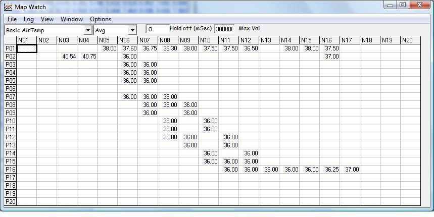
here's a Power FC log from around 2004 that got me thinking... a dyno run around 20 psi and no IAT change from 2000 rpm?
humorous.
here's a Power FC log from around 2004 that got me thinking... a dyno run around 20 psi and no IAT change from 2000 rpm?
humorous.
Last edited by Howard Coleman; Mar 1, 2021 at 02:06 PM.
So I guess that brings up the question of what is fast enough? Is the KA or Delco adequate for our purpose or is the open tip thermocouple what we want to use if possible? I see the point in knowing where are motors are at to prevent detonation but what effective changes can a aftermarket ECU do with that info & how fast ? I assume determine the fueling for air temp. Possibly as a safety measure in some of the software like Haltech etc. Or is this info more for determining that some part of the system needs upgraded like a intercooler or using A/I to help bring temps down on road course etc? Howard I may take you up on the offer of sending you a different thermistor type sensor if you still want to do some testing?
Thread Starter
Joined: Oct 2001
Posts: 6,279
Likes: 728
From: Florence, Alabama
"Is the KA or Delco adequate for our purpose or is the open tip thermocouple what we want to use if possible?"
i guess we won't know until they are tested. i am happy to test any thermistor...
as to the "why" of it all Mike, i believe your second thought is primary:
"for determining that some part of the system needs upgraded like a intercooler or using A/I to help bring temps down?" i see many systems that have to be on the edge. one of the biggest contributors is having the air filter anywhere near the IC. i could write a book on it. wait i did. check the "System Design Section" of my site.
as to engine preservation i think an active knock system is key. if you have knock you need help on the next rotor face. at 9000 rpm there are 60 of them in one second. cutting boost or fuel, both of which take multiple seconds won't get it done. reducing ignition to zero happens on very close to the next rotor face. it has always worked for me.
FWIW, i am going to input a few other calibrations for the current thermistor. it currently is calibrated as a Bosch NTC. my Link G4X Extreme has a fair amount of options although i did pick the one that generated the closest to ambient.

Full Member
Joined: Oct 2019
Posts: 80
Likes: 22
From: near Deals Gap
Some more data points:
I have a Haltech 2500 connected to a TCA4 box which is connected to three sensors. One is a Haltech brand thermocouple for downpipe EGT and two Sensor connection thermocouples which I use for IAT readings. One is just after the turbo output, i.e. pre-intercooler and the other is in the Greddy elbow.. I still have the stock IAT in upper intake. I have have re-designated the thermocouple in the elbow to be the Intake Air Temp (Mike93r1). I used generic sensor inputs and designated the manifold sensor as InManTemp and the Turbo output thermocouple as TurboAOT (output air temp). The stock IAT reads slow so I have the Haltech set for 1 second polling of it, the thermocouple are rated for 4 times a second so I have them set to poll that way.
I see results similar to that which Howard describes with regards to reaction time between the thermocouplles and stock resistor sensor. Low speed, no load driving I see TurboAOT at about 10-15 above ambient and IAT back down to ambient. The max temps I've seen are approx 250F Turbo AOT and IAT max at 125F. A spirited mountain run generally produces a these type of temps: 75F ambient temp.
InManTemp - 97 to 113 F.
IAT @ elbow - 89 to 119 F.
Turbo AOT - 131 to 226 F.
A single pull within this set (about 2/3 point) looked like this.
InManTemp - 101 to 102 F.
IAT @ elbow - 98 to 105 F.
Turbo AOT - 178 to 214 F.
This single pull was 4.4 seconds long 32 to 70 mph in second gear. Notice the stock sensor only notices a degree of change while elbow IAT thermocouple logged 7 degrees. The TurboAOT was a 36 degree changes, approx. 9 degrees per second and the slope showed each degree changed.
Heat soaked temps normalize much more quickly with the thermocouples, A big part of this is likely due to the fact the temp tip is in the middle of the air stream and not on or near the wall.
Thread Starter
Joined: Oct 2001
Posts: 6,279
Likes: 728
From: Florence, Alabama
just visited the sensor comparison video and noticed that "comments turned off."
probably not due to the content being offensive to children.
more likely due to the content offensive to knowledgable people.
probably not due to the content being offensive to children.
more likely due to the content offensive to knowledgable people.

Good work, Howard! Nice to see this project coming to fruition.
The two sensors I sent you were purchased from DriftinJim via the parts forum back in Sep'18. My understanding at the time was the black one is the Triumph air temp sensor typically referenced on the forum, and the green one is another version of the same(?); both being superior to the OEM IAT sensor.
The two sensors I sent you were purchased from DriftinJim via the parts forum back in Sep'18. My understanding at the time was the black one is the Triumph air temp sensor typically referenced on the forum, and the green one is another version of the same(?); both being superior to the OEM IAT sensor.
Last edited by Topolino; Mar 3, 2021 at 10:28 AM.
Full Member
Joined: Nov 2016
Posts: 102
Likes: 15
From: Edmonton
Good work, Howard! Nice to see this project coming to fruition.
The two sensors I sent you were purchased from DriftinJim via the parts forum back in Sep'18. My understanding at the time was the black one is the Triumph air sensor typically referenced on the forum, and the green one is another version of the same(?); both being superior to the OEM IAT sensor.
The two sensors I sent you were purchased from DriftinJim via the parts forum back in Sep'18. My understanding at the time was the black one is the Triumph air sensor typically referenced on the forum, and the green one is another version of the same(?); both being superior to the OEM IAT sensor.
While I too think it�s suspect that the video above has the comments turned off, and he�s using the wrong thermocouple, but none of those thermistors reached anywhere near as slowly as in Howard�s test.
Thread Starter
Joined: Oct 2001
Posts: 6,279
Likes: 728
From: Florence, Alabama
i certainly agree that my data is questionable since i don't know what sensor i have and i don't know the scaling. my ECU provides 22 options as to scale and a couple of them come close when comparing ambient temp w the motor off. a few others come close w the motor off and then as soon as i start the motor and am looking at, say, 100 F they are way off. there is a high probability the the scaling isn't totally correct.... although the current sensor calibration is generating readings at steady state around the 10 degree area of matching my thermocouples..
i did another run yesterday to around 15 psi.
looking closely at is quite interesting. picking near the end of the run and looking at the thermistor output:
4:01.882 114.6 F
4:02.102 114.8 F .220 second interval
4:02.241 115.0 F .139
4:02.382 115.2 F .141
4:02.518 115.0 F .136
4:02.666 114.8 F .148
4:02.852 114.6 F .186
4:03.027 114.4 F .175
while the calibration is probably slightly wrong a few observations can be made.
the sensor is fast. about 6 data points per second. good enough for me.
the sensor is range bound. notice all the changes were only two tenths of one degree F. i doubt whether a slightly different calibration would free this specific sensor from it's constraint which is probably mechanical.
now let's take a look at my thermocouple data:
4:01.882 125.2 F
4:01.916 126.3 F .034 of one second interval
4:01.948 130.5 F .032
4:01.980 131.0 F .032
4:02.018 129.7 F .038
4:02.055 131 F .037
4:02.093 127.8 F .038
4:02.132 128.3 F .039
4:02.168 130.5 F .036
4:02.204 131.9 F .036
4:02.241 130.8 F .037
4:02.279 127.6 F .038
4:02.311 122.5 F .032
4:02.343 112.6 F .032
4:02.377 100.8 F .034
4:02.414 107.2 F .034
16 data points in .523 of one second. perhaps the speed differential, while HUGE, is a distinction without a difference as the thermocouple is fast enough.
of course the big difference and it is a distinction WITH a difference is the range of the data points. notice it was able to record a drop of 9.1 degrees in .034 of one second. the next data point was a drop of 11.8 degrees in .034 of a second followed by and increase of 6.4 in .034 of a second. so much for the concept of "heat soaking" in the video. after looking at the data i can see why EGT Technology states their thermocouples can detect one misfire at 8000 rpm.
as always i remain interested in testing any thermistors hopefully with calibrations included.
Last edited by Howard Coleman; Mar 4, 2021 at 08:31 AM.
^The resistance levels of the two thermistors you have should be close to the following:
@ 68 *F (20c) = 2.27 Ohms
@ 176*F (80c) = 0.34 Ohms
Note: The Triumph sensor has a reputation for being very fast-acting (relative to stock version), w a thread size & pitch of M10x1.25; same as OEM.
Here is a relevant forum link where it lists a table of voltage vs temperature values for the Triumph sensor as constructed by another member; perhaps useful to compare values utilized by the current ECU to see if at least in the ballpark (I.e., 32F = 4V & 178F = 1.06V).
https://www.rx7club.com/single-turbo...ation-1144689/
Last edited by Topolino; Mar 4, 2021 at 11:51 AM.