When you click on links to various merchants on this site and make a purchase, this can result in this site earning a commission. Affiliate programs and affiliations include, but are not limited to, the eBay Partner Network.
thanks for that. i bought the proper sized drill and have a couple of nice pieces of aluminum so i have it covered. i am finishing re-assembly of my car after changing the studs to Chips and expect to have some comparative data soon.
i think IAT is a big deal.
Well I hate to jump in and step all over the post, but I purchased a Triumph motorcycle IAT sensor on ebay as some recommended. Cost I believe was $10-$15. Mounted the IAT sensor in the UIM where the stock IAT goes (I believe).
Here is a log from over the weekend on a long 3rd to 4th gear pull on 93 octane with a conservative tune.
If you look at the purple line, ss soon as I jump on the throttle, you can see the temps start to move up (starting at 111F) and near the top of 4th the IAT's peak at 152F. A second off the throttle, and IATs are dropping... So maybe a second delay...
my interest is primarily IAT and i am not out to prove sensors other than my thermocouple don't work. i just want to know what the real deal is. if the less expensive way works great.
i have now finished making my bung for the fast acting sensor, i have a bung for the open air sensor that came w my ViPEC and will be logging all 3 at the same time.
since you posted some IAT data i thought i would take a look at what i have. here's a run in 3rd gear. 93 pump gas with approx 1000 cc of 100% methanol as AI. just about 25 psi, EFR 9180 making 585 rwhp.
subsets from top to bottom are:
RPM
Boost
TPS
IAT (F)
AI system pressure (PSI)
first graph shows the point where my IAT starts... at 77 F and around 9 psi. this is at 2.59.706 on the log.
the second graph shows close to the top of IAT at 126 F at 3.00.441
since the high of my IAT was 129 F, 94% of the total rise in my IAT took place in .735 of one second.
your log looks like a slow sensor trying to catch up as it looks like a linear staircase. which raises the key question:
did it ever catch up? your readings in third span 6 seconds of rising readings. the question is, were your IATs actually rising during that period or was the sensor just limited as to speed.
my data shows that IAT rise very sharply and then decline. this could be for numerous reasons such as system design and methanol.
my last graph of the run shows the last 100% TPS at 7772 RPM, 24.9 psi boost, 585 rwhp and 117 F IAT.
towards the top of a run charge air coming out of the compressor is over 300 F. since the temperature is a function of compressor slippage rather than raw flow 300+ is existent whether you are running the (godawful) OE system or a high output single setup.
gasoline autoignites at 495 F. since there is overlap between the intake and exhaust even on the stock FD ports you are sweeping some exhaust gas into the intake stroke... no oxygen, just HEAT.
it is therefore important to feed the motor with really low temperature charge air... and you are starting at the turbo above 300 F.
all of my system design is driven by heat and flow considerations. of course instrumentation is needed or your are blind.
in addition to my air thermocouple in the UIM i have an air thermocouple between the turbo and the intercooler.
as mentioned, i normally see air temps out of the turbo just above 300F. a combination of my favorite intercooler, the stock location Pettit Coolcharge 3 (around $1400 BTW, call Cam) and the meth remove 200 F from my charge air!
given the exhaust speed is measured in terms of Mach by BW the intake must also be running at a similar speed, imagine the amount of heat that needs to be removed from the charge air.
so let's see, we are running a super dooper V mount that is really going to drop IAT... and we locate the air intake right in the path of all the heat we are extracting?????? yikes!
i plan to add an additional 500 CCs of meth, bringing it up to 1500 CCs and expect my IAT to drop into the 50/60 F range. ( a number of years ago i was up to 3000 CCs but don't want that aggressive a bet these days)
in addition to detonation avoidance, the other reason to lower IATs is POWER.
Power is simply burning oxygen molecules. if you compare two volumes of air at a similar pressure the hotter volume will have less molecules as they are vibrating as they heat so each molecule takes up more space. more space, less molecules. less power. that's why your car is supersonic when the temps drop and it also leans out because of so much more oxygen at the same boost.
low IATs = less chance of detonation and more power.
meet with cam a few months back and preached the same u are about intake temps. he also mentioned u.
he sends his regards
I had made a lim shield, and use a air box wrapped, inconel shields on manifold and turbo.
he nicknamed me mr.shields Ha
he is the reason I kept my pettit IC
ever check wat ur temps were like without the air diverter for ur air filter HC?
just finished installing my UIM yesterday and it does include the "fast" thermistor along w my thermocouple so we should be getting the comparative data shortly.
if you visit an industrial facility where they really need to mitigate heat transfer you will find mica.
if you take a look at the space shuttle's business end you will find a substance that uses mica
or, if you look carefully, you will see a quarter inch sheet of mica on duty here...
i initially ran an 1/8 in sheet and prior to installing it used a 1300 F propane air torch to heat one side for 2 minutes. i could touch the other side within one inch of ground zero with zero problems.
McMaster Carr sells a perfect 12 X 13 inch piece (1/4). so that takes care of the LIM, the PTP turbo blanket greatly reduces under hood temps which often influence IAT. PTP uses a mica like substance in the blanket.
Howard, what was your reasoning behind the switch from 1/8" Mica to 1/4" Mica? The one downside is that you can't exactly shape the stuff to your liking. Not malleable.
I'm going to have a hell of a time with the wastegate coolant paths to notch/slot/shape things to my will. Those might have to be pass-throughs with high temperature grommets. Then at the front of the manifold, it's WAY crazier. Rear I might be able to get away with.
1/4" Thick here won't work for me. 1/8" Should be doable.
initially i was given a sheet of 1/8 inch mica by a friend who oversees a large metal/industrial operation and told to run it. when this guy talks i listen.
i did the propane torch experiment w the 1/8 inch sheet and really did heat it for 2 minutes and i could have literally touched the exact spot on the backside but sort of chickened out. i did have my finger an inch from it and it was barely warm..
after running it for a few years i was looking at the McMaster Carr catalog and noticed they had 1/4 inch so since i (just) had the room i made the trade up.
given the location of your hotside i would say you absolutely need mica. while you may not be able to slide a flat plate of it in you could work the material a bit and probably get most of your lim protected. the material is easy to saw and drill and 1/8 will absolutely get it done.
i believe the PNs are: 85165K81 1/8, 85165K82 is 1/4
Wow, I�m pretty impressed with that mica stuff, is it easy to work with?
for example, to make a air box out of, is it heavy?
on the website they also have a flexible mica sheet, I�m thinking this would be easy to shape and layer up with a few layers thick and then set it with a type of resin to make it hold its shape for complicated area�s????
i also found another type of mica sheet where when you wet it it becomes mouldable but after its heated a few times it will hold its shape, but i cant find which site it was on 😩
I�m looking at ways to really keep my IAT temps down, to make everything as efficient as possible, such as ceramic coating my exh housing and manifold aswell as turbo blanket and heat wrap, heat shields around my LIM, cold air box etc,
also preturbo water/meth injection (pumpless system).
im also on the hunt for IAT sensor, so i really look forward to the results of this test, I�m heading towards the t/c as i will be running 2 for my egt and the t/c amp box for haltech has 4 inputs so may as well make use of them all
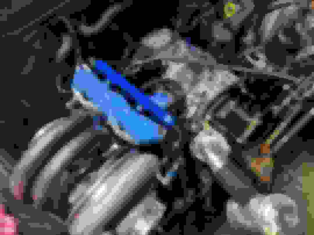
Now that my car is running. I trying to do what Howard did with mica when I saw his post long time ago. My LIM and and turbine housing are hight temp ceramic coated, but they are very close and the 1/4 " plate wont fit.. i was thinking a inconel sheet to go around that spot.
You can see the thickness of the mica and the little room between LIM and turbine housing.
Thank you Howard for this I bet it works great.
The Mica sheet is a really good, cost effective solution, as long as you can make it fit. An inconel shield like is used on a previous post, will likely be what you need. Whatever your solution try to get at least a small air gap between the turbine housing and shield. This will allow the reflective properties of the shield to keep the radiant heat away, and prevent the heat from being directly conducted.
By fitting it that close, you've made your work harder. But I'm sure you can overcome this engineering hurdle.
I now have a line on an ECONOMICAL fast acting M10x1.25 air intake sensors with EV1 connectors. YES! They take some time to get here, but quality is amazing and it's direct bolt-in for FD Upper Intake Manifolds!
Howard - What ever came of your comparison? Assuming the K type thermocouple produces the fastest responding and most frequent reading delivery, what would a solution be for a stock UIM setup using the stock IAT sensor port. Stock port being 10mm x 1.25 pitch. Without having to modify the UIM, is it possible to use a thread adapter to prevent tapping the intake. There seems to be several options on the market that are fast reacting that you can plug and play. It's just, if $50 separates me from having the fastest reacting and most frequent type of intake temp reading from a fast(er) than stock sensor, then its worth my time and engines time to make that small leap up. Can the pig tail of the K type sensor and the stock sensor wires be re pinned with a different connector?
I went ahead and fitted the same thermocouple to my intake. Unfortunately I didn't see any rise in IAT during a pull with the Triumph sensor and still see nothing with the thermocouple, so I can't say whether it made much difference. I'm running 20psi on stock twins with a 21" x 12" x 4" Plazmaman front mount intercooler.
Howard - What ever came of your comparison? Assuming the K type thermocouple produces the fastest responding and most frequent reading delivery, what would a solution be for a stock UIM setup using the stock IAT sensor port. Stock port being 10mm x 1.25 pitch. Without having to modify the UIM, is it possible to use a thread adapter to prevent tapping the intake. There seems to be several options on the market that are fast reacting that you can plug and play. It's just, if $50 separates me from having the fastest reacting and most frequent type of intake temp reading from a fast(er) than stock sensor, then its worth my time and engines time to make that small leap up. Can the pig tail of the K type sensor and the stock sensor wires be re pinned with a different connector?
FYI I fitted mine into the stock port using an adapter, no issues.
I went ahead and fitted the same thermocouple to my intake. Unfortunately I didn't see any rise in IAT during a pull with the Triumph sensor and still see nothing with the thermocouple, so I can't say whether it made much difference. I'm running 20psi on stock twins with a 21" x 12" x 4" Plazmaman front mount intercooler.
That's a healthy sized intercooler for the twins, NICE! It sounds as if the sensors are not operating correctly. Did the stock sensor spit out readings before switching? May be a calibration issue or wired incorrectly.
That's a healthy sized intercooler for the twins, NICE! It sounds as if the sensors are not operating correctly. Did the stock sensor spit out readings before switching? May be a calibration issue or wired incorrectly.
Yeah all three sensors I've tried work correctly, no odd behaviour. I suspect if I did repeated back to back pulls the temperature would increase but I'm not getting the kind of rapid change in temperature that Howard is seeing so unfortunately I can't compare the response time between them.
i remain as interested as ever re IAT. making power and not breaking motors is all about density and any uptick helps greatly. IAT thermocouples are the ruler.
2020 featured a move from Wisconsin to Georgia which is very exciting to me as no more being parked for almost 6 months a year. following getting situated (around November) a succession of events ocurred that left me mostly on the sidelines. for instance my wonderful ViPEC V88 decided to retire... something about the motherboard. i now have the most recent iteration of my V88... a Link G4X Extreme and it is amazing. it took the better part of a month to transfer my map to the Extreme and i discovered Evans Performance Academy in the process. what an awesome and affordable resource. almost every ECU is totally dissected. there are over 60 (!) 30/45 minute tutorials on my specific ECU. it is totally crazy what my new ECU can do.
whipping my instrumentation into shape presented another challenge. i run 4 thermocouples.... two EGTs, one air thermocouple just after the turbo before the IC and one in the stock location under the UIM. a year or so ago i discovered the Innovate TC4 Plus thermocouple amp. since it had 4 channels i swapped it in. it never produced 4 temps. i switched back to what i had previously run which is two dual channel amps from EGT Technologies as well as a set of four new thermocouples from "The Sensor Conection." i finally now have all four temps going as well as my "fast" acting thermistor located in the UIM. you can also see the fitting for my thermocouple in the stock location..
since i am breaking in a new ECU and map i am in the process of adding boost. i did a tip toe to around 15 psi just for a brief period to get a handle on my AFRs. here's a snippet. steady state TPS (24.7%) zero boost/vacuum air out of the turbo is 134 F, IAT at OE location from the thermocouple is 87 F and at thermistor under the UIM is 78. the thermistor is the almost flat line.
at 15.7 boost, 33.8% TPS, 4879, air out of the turbo is 188.2, IAT at the OE location thru the thermocouple is 88.5 and 77.7 at the thermistor. none of this is surprising and doesn't mean much until we get into much higher TPS settings and rpm but i am happy to just being able to generate some data.
now if it will just stop raining.
here's the log:
i will be adding an additional pressure sensor at the IC outlet as well as another thermocouple in the same place. the addition of these sensors will allow me to isolate the IC and get data as to pressure drop and thermal efficiency. the primary reason for this is it will allow me to generate comparative data when i swap in something possibly quite special. stay tuned.
Last edited by Howard Coleman; Feb 19, 2021 at 09:38 AM.
I figured you guys would find these logs interesting, similar to what HC is doing.. I installed temp and pressure sensors in several spots, measuring ambient, pre-turbo, pre-intercooler and manifold. you can calculate air density from temp and pressure (assuming constant humidity). the air temp sensors I am using are the haltech 1/8npt open air sensors. my setup is EFR7670 on a stockport rew, pump gas, vmount intercooled only, makes about 350whp
in the log
aat = ambient air temp
aap = ambient air pressure
tcit = turbo charger inlet temp (turbo inlet)
tcip = turbo charger inlet pressure
cacit = charge air cooler inlet temp (turbo outlet)
mat = manifold air temp (intercooler outlet)
emap = turbo manifold pressure
column M = ambient density
N = turbo inlet density
O = turbo outlet
P = intercooler outlet (manifold) density
looks like the haltech sensors go from 145F to 200F in 2 seconds, about 25deg/sec. Cool to see how much density is increased by the turbo vs intercooler. and the slight drop pre-turbo due to filter restriction
Last edited by gxl90rx7; Feb 19, 2021 at 11:38 AM.
I figured you guys would find these logs interesting, similar to what HC is doing.. I installed temp and pressure sensors in several spots, measuring ambient, pre-turbo, pre-intercooler and manifold. you can calculate air density from temp and pressure (assuming constant humidity). the air temp sensors I am using are the haltech 1/8npt open air sensors. my setup is EFR7670 on a stockport rew, pump gas, vmount intercooled only, makes about 350whp
in the log
aat = ambient air temp
aap = ambient air pressure
tcit = turbo charger inlet temp (turbo inlet)
tcip = turbo charger inlet pressure
cacit = charge air cooler inlet temp (turbo outlet)
mat = manifold air temp (intercooler outlet)
emap = turbo manifold pressure
column M = ambient density
N = turbo inlet density
O = turbo outlet
P = intercooler outlet (manifold) density
looks like the haltech sensors go from 145F to 200F in 2 seconds, about 25deg/sec. Cool to see how much density is increased by the turbo vs intercooler. and the slight drop pre-turbo due to filter restriction
Excellent info! Got a question, is that info based on a single gear pull? Would love to see the same info on a 3 gear pull.
"is that info based on a single gear pull? Would love to see the same info on a 3 gear pull."
this is very close to the ultimate question re our cars and IAT.
IC heat soak, or lack thereof, may be the KEY.
for example i know of a dyno test with an NSX comparing different IC cores.
a high quality bar and plate IC lost 50 rwhp on the third pull. all due to heat soak. another IC core was immediately swapped in and had virtually no power loss after 3 runs. of course airflow thru the IC on the dyno is somewhat limited and i don't know where the IC was situated but i do know there was almost no power loss after 3 runs w the different core. i have that core fixtured for my FD and will be testing it soon.
meanwhile for most of us, especially on a road course IC heat soak is a serious dynamic challenge which calls out for proper instrumentation and eventual help.
Last edited by Howard Coleman; Feb 23, 2021 at 07:58 AM.
i dont have any recent logs with longer pulls, but here is one from last year when i was running just off the wastegate spring 3rd - 5th. i was also running a more restrictive filter back then, you can see the density drop in the turbo inlet.
it does seem that the traditional open air temp sensors heat up fast, but take a while to cool back down. yea the question is, is that just because the throttle is closed and less airflow to dissipate heat soak in the sensor or IC heat soaking
gauge pressure
density
Last edited by gxl90rx7; Feb 20, 2021 at 09:21 AM.