
goodby resistors, hello Peak and Hold


7 Rx-7s since 1980
Joined: Mar 2004
Posts: 438
Likes: 1
From: oHIo
I would assume that there would be no issues with a Racelogic TC unit installed. Since it works with stock or aftermarket (does not care what is downstream from the ECU connection) there should not be an issue. End assumption.
Tony
Tony
I know, but for one reason or another I never installed the flyback for it, so I have to do that before I can use the Peak and hold.
Junior Member
Joined: Jan 2007
Posts: 28
Likes: 0
From: Korea
crispeed & atihun: Does this mean that the FJO can run both high AND low impedence injectors? I understand your reasoning, but I thought that the FJO was designed for low impedence only.

Rotary Enthusiast
Joined: Feb 2001
Posts: 1,094
Likes: 0
From: Orange County, CA
It would be something to verify with FJO, but when I bought it a few years ago I was told by them that it reproduces the ECU signal identically. The peak and hold is caused by the actual draw from the injector. Therefore I would think that since the high impedance injectors use a lower current that it 'should' work... I'd call them.
As for my setup, I went with new low impedance injectors for the primary because my original engine/injectors had 110K before it passed to the other side.
As for my setup, I went with new low impedance injectors for the primary because my original engine/injectors had 110K before it passed to the other side.
Junior Member
Joined: Jan 2007
Posts: 28
Likes: 0
From: Korea
atihun: thanks for the reply. I will call FJO as suggested. But I guess your solution is the most obvious one: to use low impedence injectors for BOTH primaries AND secondaries.
Although for my setup, this means that I need to check availability of 550cc low impedence injectors.
Although for my setup, this means that I need to check availability of 550cc low impedence injectors.
Rotary Enthusiast
Joined: Feb 2001
Posts: 1,094
Likes: 0
From: Orange County, CA
FYI.
According to FJO, the driver will drive both high and low impedance injectors so you can have high impedance primaries and low impedance secondaries and hook them all through the FJO.
The driver will switch to saturated mode on the two channels that are running the high impedance injectors.
According to FJO, the driver will drive both high and low impedance injectors so you can have high impedance primaries and low impedance secondaries and hook them all through the FJO.
The driver will switch to saturated mode on the two channels that are running the high impedance injectors.
"Further, the mountainous peak in my base fuel map at transition is a now a linear slope."
I have experimented with my Primary/Secondary (%) and Secondary Transition (ms) with 550/1600 Injectors.
My transistion was poor even when using the standard ( 850/1600)* 1.5ms formula for calculating the new Secondary Transition (ms).
My tested and current setup of Primary/Secondary (30%) with Secondary Transition (.100ms) works great. When I compare the logged chart of the transistion from "primaries" to "primaries + secondaries", the improved results
are very noticeable. I do not have any moutainess peaks! Maximized injector setup helps a lot.
sorry it may be simpler than i tihnk, i could be having a brain fart

Rotary Enthusiast
Joined: Feb 2001
Posts: 1,094
Likes: 0
From: Orange County, CA
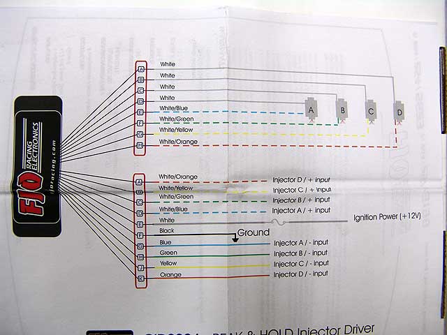
The bottom set of wires (A-K) from the picture show the lines from the ECU + Ground + 12V source to the FJO. There is a common ground that all the injector grounds come to.
The top set of wires (A-H) goes from the FJO the the injectors.
The top set of wires (A-H) goes from the FJO the the injectors.
still confused. the injectors dont have a common ground.. they have +12v in common, the ecu provides a ground to turn them on/off
Rotary Enthusiast
Joined: Feb 2001
Posts: 1,094
Likes: 0
From: Orange County, CA
Take a look at the cars wiring diagram. The ECU has 4 (+) wires and 4(-) (from 1 (-) ) wires coming from the ECU to the injectors. All you are doing is putting the FJO in the middle of the wiring. Then you add an additional (+) and (-) wires to the FJO from a 12V source (an ignition source so there's power when the key is turned) and a ground wire that you ground to the body.
I won't let go


Joined: Aug 2002
Posts: 3,871
Likes: 23
From: Chi -> Maidstone
So I think this was kind of asked, but I'll ask it in layman's terms...
What would be either more beneficial/generally better to run?
High impedance saturated injectors straight off the ECU or;
Low impedance peak and hold with the FJO in between?
This is mainly directed towards primary injectors as it's almost guaranteed that someone will run low impedance injectors for secondaries.
It was touched on that the latter is better performing and thus may further decrease any lag and improve tunability.
Allow me to post my thoughts on installation. I spoke to a guy at FJO a few days ago about wiring up my 2nd gen Turbo II to this injector driver box which I just received about a week ago. My wiring diagram appears to be a little different than the pic posted by gxl90rx7. According to my discussion with him, the new wiring diagram reflects recent changes that FJO has made to their 4 channel box in order to allow it to work on certain cars that trigger their injectors by +12V, unlike most cars.
My box has fewer wires in general. Note that both harnesses appear to have eliminated wires that were likely to be spliced together anyway. Thus there is one white feed wire on the top harness instead of 4 individual ones like in earlier versions of the box.
So on an 88 T2 you would cut the 4 wires that connect to the each ECU. The ECU side of the wire connects to the FJO harness with solid colored wires, while the injector side of the wires goes to the striped FJO harness. Then you use the black/yellow common injector feed wire which, according to FSM page 50-22, comes from the main relay, powers a bunch of stuff like the coils, and ultimately runs to each of the injectors. Cut that wire. The main relay side goes to the white wire in the solid colored FJO harness. The injector side of the black/yellow wire connects to the white wire in the striped FJO harness.
According to the FJO rep the pink wire in the solid colored FJO harness is designed to work with those few unusual cars (European apparently) that use a switched +12v instead of a switched ground. On our cars you should just connect that pink wire to the white +12v wire on the same harness, the one connected to the main relay side of the black/yellow wire.
Does this wiring make sense? I think the only thing different on an FD is where you would get the injector feed wire that is cut to power the solid white wires on each FJO harness. I'm about to go start on this installation tomorrow, but I won't be able to start the car for a l few weeks to test everything because I'm waiting on other miscellaneous parts.
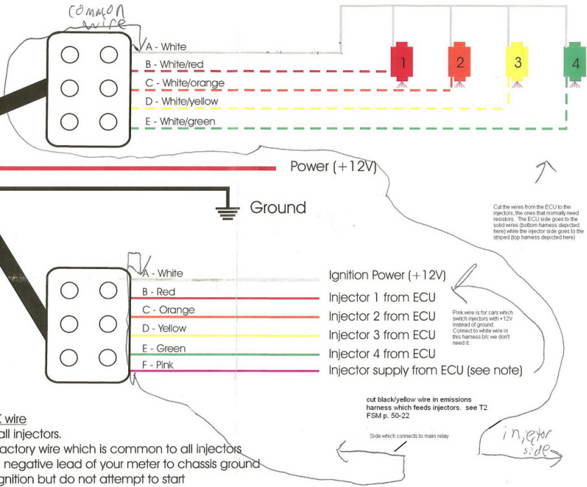
See http://www.geocities.com/arghx/FJOinjectorWiring.JPG for an easier-to-read diagram.
My box has fewer wires in general. Note that both harnesses appear to have eliminated wires that were likely to be spliced together anyway. Thus there is one white feed wire on the top harness instead of 4 individual ones like in earlier versions of the box.
So on an 88 T2 you would cut the 4 wires that connect to the each ECU. The ECU side of the wire connects to the FJO harness with solid colored wires, while the injector side of the wires goes to the striped FJO harness. Then you use the black/yellow common injector feed wire which, according to FSM page 50-22, comes from the main relay, powers a bunch of stuff like the coils, and ultimately runs to each of the injectors. Cut that wire. The main relay side goes to the white wire in the solid colored FJO harness. The injector side of the black/yellow wire connects to the white wire in the striped FJO harness.
According to the FJO rep the pink wire in the solid colored FJO harness is designed to work with those few unusual cars (European apparently) that use a switched +12v instead of a switched ground. On our cars you should just connect that pink wire to the white +12v wire on the same harness, the one connected to the main relay side of the black/yellow wire.
Does this wiring make sense? I think the only thing different on an FD is where you would get the injector feed wire that is cut to power the solid white wires on each FJO harness. I'm about to go start on this installation tomorrow, but I won't be able to start the car for a l few weeks to test everything because I'm waiting on other miscellaneous parts.
See http://www.geocities.com/arghx/FJOinjectorWiring.JPG for an easier-to-read diagram.
Last edited by arghx; Aug 20, 2007 at 09:49 PM.
Rotary Freak
Joined: Dec 2001
Posts: 2,402
Likes: 0
From: chandler, AZ
Running them peak and hold is definately the way to go...
Lucky enough my ecu has separate drivers for primary and secondary so I can run the stock primaries saturated, but get the efficiency of the secondaries on peak and hold.
(Insert shameless plug...)
Actually, over the last few months we've been working on building an injector test bench because we were fed up with the uncertainty that any other services were currently offering. So I just wanted to let everybody know that we finally completed the bench. We've found some VERY valuable information using it and though that some others might be interested in getting detailed specs on their injectors.. So we decided on offering a dynamic injector flowtesting service.
The testing generates battery compensation values, minimum and maximum linear pulsewidths, optimum peak and hold currents, and just about any other important parameter that you can think of.
The details can be found on our website at
http://www.yawpower.com/injectordynamics.html
I won't let go
Joined: Aug 2002
Posts: 3,871
Likes: 23
From: Chi -> Maidstone
arghx...
That's about the same way I'm wiring mine though for whatever reason, your drawing was confusing the hell outta me.
I was thinking about getting a seperate 12v ignition source for the bottom white wire, but I guess it really doesn't matter. I cut the b/y on the relay side of the blue clip at the ecu. Seemed to make the most sense to me as when I pull the harness, I won't be stuck with that hanging on. Dunno how everyone else did/does it but there ya go.
It really is an easy install, but I'd definitely recommend pulling the harness altogether to make it neat. It was pretty simple though keeping everything in place. And I'm running all four on it.
I won't let go
Joined: Aug 2002
Posts: 3,871
Likes: 23
From: Chi -> Maidstone
Ok...so to those who may have been running resistors before and are now running this:
What did you change the settings to? My settings were 68 with a lag of .04 and .14. My primaries are actually 865cc so my new settings are 63, but I don't know what the lag should be. The secondaries are Bosch 1600s and the primaries are Simens 865s. After everything was said and done, she runs, but it almost sounds like she's on one rotor. They're both firing though, but needless to say I'm running pig rich. I think I've taken a whole lotta fuel out (from a 1.2 to .645) but am still seeing 10s at idle. Nothing happens as I take more out. This was a similar thing to when I initially had gone over to a single setup. The injector settings weren't perfect so I could only idle at 11 or so.
Any helpful suggestions would be appreciated to at least get the injector settings up to par.
Thanks!
^Howard I will be running this unit soon and run the pfc. If you could send me a detailed pm with what settings to change and on what page in the fc edit I would greatly appreciate it! Thanks so much for all your knowledge!!!
-Lance Mayhon
mono4lamar@hotmail.com
-Lance Mayhon
mono4lamar@hotmail.com

Joined: Nov 2006
Posts: 540
Likes: 1
From: STOCKTON, CA / VENTURA, CA
^Howard I will be running this unit soon and run the pfc. If you could send me a detailed pm with what settings to change and on what page in the fc edit I would greatly appreciate it! Thanks so much for all your knowledge!!!
-Lance Mayhon
mono4lamar@hotmail.com
-Lance Mayhon
mono4lamar@hotmail.com
Thread Starter
Joined: Oct 2001
Posts: 6,279
Likes: 728
From: Florence, Alabama
joe-c...
thanks for the suggestion. i have been getting a large number of PMs.
as i may have mentioned, i run 850s and 1600s. actually as per RC they are 888/1658.
on my Settings 3 page i have them listed as per RC. i am quite sure if you just listed 850/1600 they would run similarly and you would just tune it for your AFR target...
i elected to leave the lag unchanged at .04 and .14. Pri/Sec trans is 40%. Sec transition in Ms is .996.
Injector Overlap is 4 3 2
i had a Tip In stutter at Very Light Throttle and completely eliminated it by changing Settings 2 Injector vs Accel TPS1 (left column bottom) input to zero. it had been 20.... all probably unrelated to P&H setup but an FYI.
i have been on the dyno twice w these settings and they work excellently. i am making 364 ft pounds of torque at 5850 at 16 psi on pump gas. i have a backpressure problem and should have my turbos back sep 14. stage 5 hotsides for my two TO4s should do the trick. i run 93 octane and methanol. see details of my tuning venture in the Auxiliary Injection Section thread "80% pump, 20% methanol."
it appears that there is an approx 5% fuel saving running my secondaries P&H based on duty cycle and Ms settings in Base Fuel.
i run my secondaries P&H and my primaries saturated.
BTW, Railgun... re rich idle and settings. i believe there is a minimum Ms that the Power FC will open the injectors and i think it is 1.6 Ms. (you can change the lag and fool the ECU into lower ontimes but you often create a difficult tip in problem).
so if you input, a lower ontime the PFC disregards it. you can confirm this buy checking the Watch for Advanced Injector Front Primary. it posts as Ms. try to lower the setting and you should see it won't drop below the minimum regardless of what number you enter.
the FJO Peak and Hold module has been really nice in 07. it is sort of like my Exedy twin cerametallic clutch. i have totally forgotten it is on the car. it just seemlessly works.
the major reason i bought the FJO module was i couldn't tune out the bulge in my base fuel at secondary transition. while i bumped ontime over 50% to get a stable AFR i just felt that this wasn't the right way to do it.
my transition Ms now are linear.
i like linear.
hc