
Rtek New boost-based timing maps


Thanks. This will be my first time tuning rotary. I am used to boingers with ignition, valve, and afr to tune. This leading and split thing is what is throwing me for a little bit of a loop.

crazyrx7
Joined: Jan 2010
Posts: 184
Likes: 0
From: texas
barely got my rtek 1.8 for my s4 turbo! ok i am completely new to this so please bare with me! ok please correct my if im wrong the bottom numbers would be rpms and the left would be psi?? second from my understanding you can only use palm to datalog your timing?? so how do you adjust these maps?? and how do you connect datalogger into the rtek??? sorry if this isnt the right place to ask this but you guys seem to kno alot! lol
*sorry dont mean to thread jack
*sorry dont mean to thread jack
1.8 doesn't support datalogging and tuning. you can run a fuel controller on top of the 1.8, but the stage 2 is the only unit that tunes off of a palm pilot. the 1.8 just plugs up and goes after new injectors. i ran a 1.7 until recently and i really enjoyed it. have fun.


This is the portion of the stock leading map where you'd be under boost. Note that this is not absolute, since the ECU can still make small corrections at pressures up to 9psi. But my data logs have shown lead timing is usually very close to what is shown here. I didn't make a table for split at the time, but it is roughly 15 degrees by default at higher load levels.
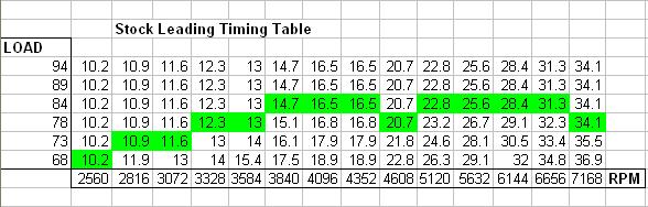
That's for s4 of course. It looks fine for a mostly stock car, but I'd say it's too aggressive for a reliable high compression setup. And in the cells you've highlighted, the timing has already hit a "floor" of sorts. It won't retard any further. Going much over 25 degrees up top is IMO pushing it on a more heavily modified car with normal 93 AKI fuel.
Just for comparison purposes, here's a stock Evo X tracing through its factory timing maps:
and here's a boost and AFR curve from a stock Evo X:
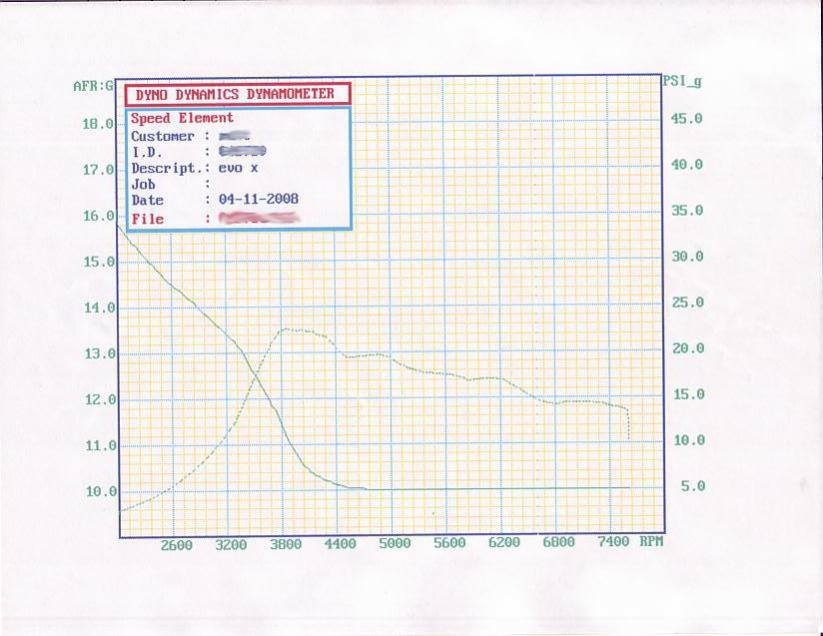
note that these images aren't all taken from the exact same vehicle
Just for comparison purposes, here's a stock Evo X tracing through its factory timing maps:
and here's a boost and AFR curve from a stock Evo X:
note that these images aren't all taken from the exact same vehicle
Joined: Sep 2005
Posts: 25,581
Likes: 136
From: Smiths Falls.(near Ottawa!.Mapquest IT!)
Ya know,I Sold my 2.1 because I was in a frenzy trying to get the car to Fire up.
I regretted that move,But I got the car started finally.(wiring issue,My fault)
NOW,with the Maps posted up by ARGHX,I am a real happy camper.I am going to purchase another RTEK..
some of the Mods I have done can use the Maps that he posted.
I like people that can help like that..Thank you Very Much!
It should be a fun Summer!
Zoom Zoom Boom
Joined: Nov 2002
Posts: 336
Likes: 0
From: South Florida
Here's a dumbass question I might know the answer to when I ask but Id just like ot be sure.
arghx - I'm going to try to use your conservative map and then tune my fuel but, Where are the trailing maps? I havnt enabled map based timign so i dont know what it looks like in there yet.
Are they automatically generated throught the split?
arghx - I'm going to try to use your conservative map and then tune my fuel but, Where are the trailing maps? I havnt enabled map based timign so i dont know what it looks like in there yet.
Are they automatically generated throught the split?
Zoom Zoom Boom
Joined: Nov 2002
Posts: 336
Likes: 0
From: South Florida
I understand, input the leading, then the split, to give me the trailing. Thanks!
So I would be using these?
LEADING
AND THIS FOR SPLIT
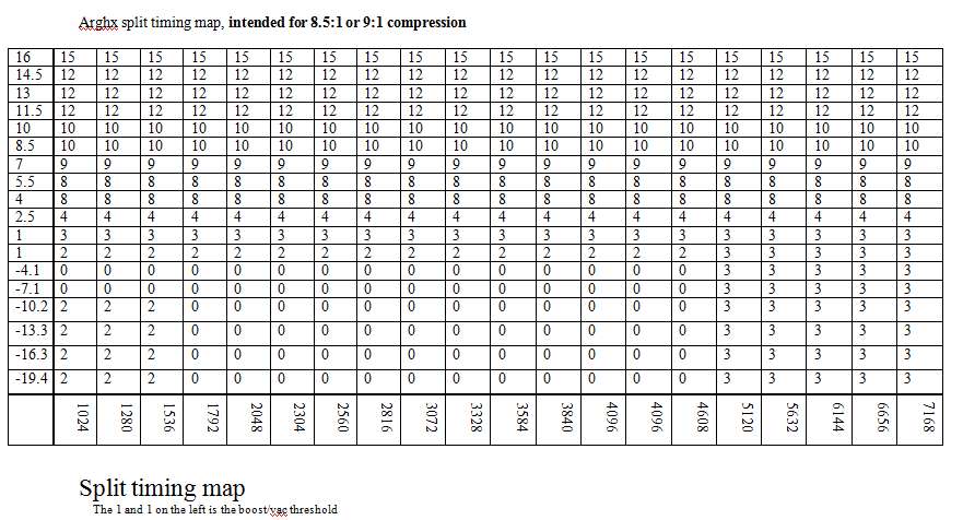
And what about the 2 missing rows? I read to repeat last but what about above 16? I dont have enough experiance to figure out the new row.
So I would be using these?
LEADING
AND THIS FOR SPLIT
And what about the 2 missing rows? I read to repeat last but what about above 16? I dont have enough experiance to figure out the new row.
Overboost Protection
The Rtek does not have an adjustable fuel or ignition cut should an overboost event occur. The stock turbo is prone to overboosting, sometimes even with a ported wastegate. Weather changes can also cause boost spikes with both manual or electronic boost controllers. I once severely detonated my engine on a cold night due to an 18psi spike on a stock s5 turbo with wastegate ported to the limits of the stock flapper.
One technique that has been employed successfully in FD's (which have their own overboosting problems) is the use of overboost safety rows in the timing maps. The whole point is to retard the ignition enough that the engine will have trouble building that additional unwanted boost. First we figure out the desired boost level for normal use. In our example, let's use 10psi. That's common enough on a car with stock turbo and stock intercooler. Then we ask ourselves: Ok, what is the maximum psi I will allow in the event of overboost? 1-3 additional psi is a normal range. We use this to get an idea of where to start our safety rows.
Target boost psi + acceptable overboost tolerance = Overboost protection psi
Then we have to pick the nearest boost row to that. One example:
10psi target boost + 2psi acceptable overboost = ~12psi for overboost protection. So we can pick the nearest row to that:
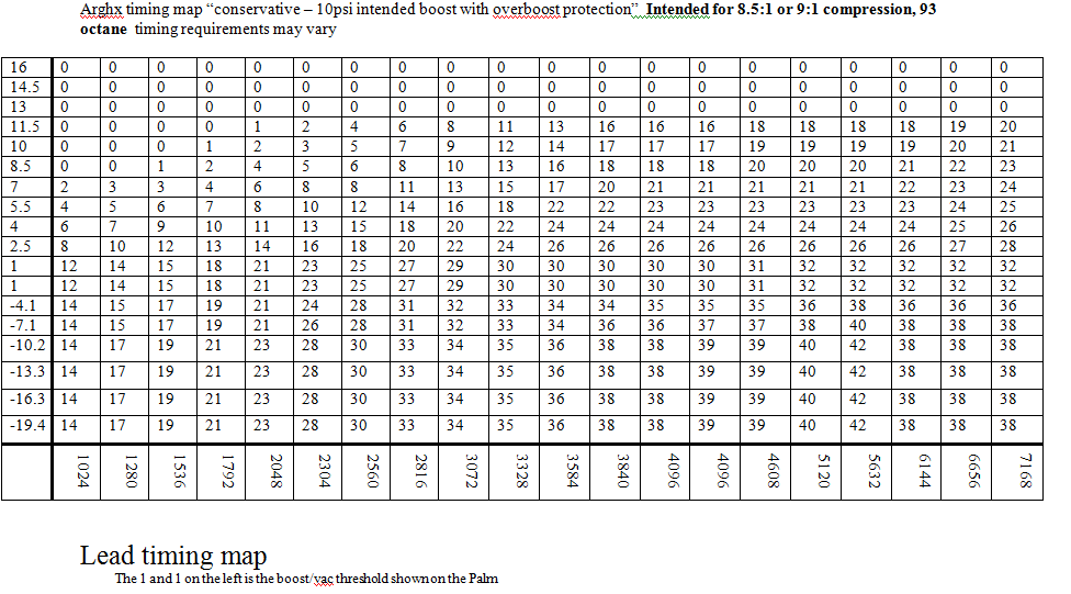

Here 13psi and above are all set to 0 degrees BTDC leading with 15 split. Once boost exceeds 11.5psi the Rtek will start pulling timing rapidly. This reduces the chances of the engine building too much boost, especially in the 3500-5500 rpm range which is especially prone to this problem on the stock turbo.
The Rtek does not have an adjustable fuel or ignition cut should an overboost event occur. The stock turbo is prone to overboosting, sometimes even with a ported wastegate. Weather changes can also cause boost spikes with both manual or electronic boost controllers. I once severely detonated my engine on a cold night due to an 18psi spike on a stock s5 turbo with wastegate ported to the limits of the stock flapper.
One technique that has been employed successfully in FD's (which have their own overboosting problems) is the use of overboost safety rows in the timing maps. The whole point is to retard the ignition enough that the engine will have trouble building that additional unwanted boost. First we figure out the desired boost level for normal use. In our example, let's use 10psi. That's common enough on a car with stock turbo and stock intercooler. Then we ask ourselves: Ok, what is the maximum psi I will allow in the event of overboost? 1-3 additional psi is a normal range. We use this to get an idea of where to start our safety rows.
Target boost psi + acceptable overboost tolerance = Overboost protection psi
Then we have to pick the nearest boost row to that. One example:
10psi target boost + 2psi acceptable overboost = ~12psi for overboost protection. So we can pick the nearest row to that:
Here 13psi and above are all set to 0 degrees BTDC leading with 15 split. Once boost exceeds 11.5psi the Rtek will start pulling timing rapidly. This reduces the chances of the engine building too much boost, especially in the 3500-5500 rpm range which is especially prone to this problem on the stock turbo.
i believe since FC leading coils use waste spark, timing set to zero (TDC) makes the waste spark timing right on the edge of start of compression on the previous cycle, so you may have a chance of knocking. it may not be that big of a deal, but you may want to use 5 degrees instead of zero for overboost protection. just a theory though
http://www.animatedengines.com/wankel.shtml
this one has an animation of waste spark with 2 rotors:
http://www.rotaryengineillustrated.c...e=0&Itemid=103
you can see you definitely dont want your leading spark to be after TDC, and combined with a CAS that isnt lined up perfectly, timing at TDC could make bad things happen
this one has an animation of waste spark with 2 rotors:
http://www.rotaryengineillustrated.c...e=0&Itemid=103
you can see you definitely dont want your leading spark to be after TDC, and combined with a CAS that isnt lined up perfectly, timing at TDC could make bad things happen

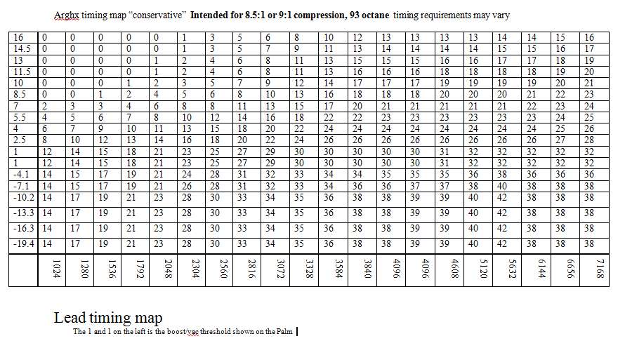
I'm fairly new to the timing maps and i'm still doing my research before purchasing rtek 2.1. My question is with the map that arghx provided, what happens after 7138 rpm? How is timing calculated if you rev higher than that?
Hey I just want to let you guys know what happens when you run a high compression rotary without appropriate spark advance maps. I have been doing some remote tuning on a couple Rx-8's, which as many of you know are 6 port engines with 10:1 compression.
I've been helping a couple guys with Greddy 18G kits. The factory Greddy emanage base map is a piece of ****. The timing maps make no sense and basically do nothing as far as retarding timing to compensate for the boost. So here is what happened to one guy who used the default Greddy map:
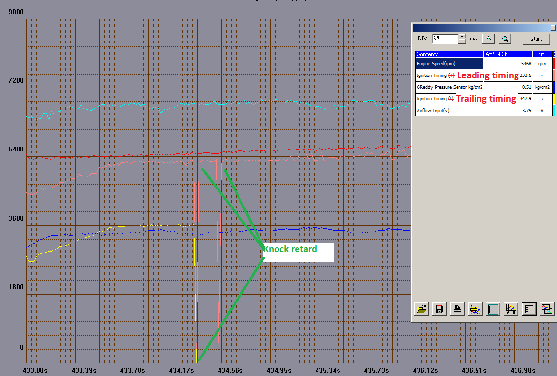
At 5500rpm the engine detonated pretty bad. The factory timing maps called for about 26 degrees leading with 15 split, which is just too much for 10:1 compression and a boosted setup. Luckily the Rx-8 PCM is smart enough to severely pull timing and the engine survived. In this case the engine was running about 7psi boost (spring pressure) on a Greddy TD06-18G with I believe the 10cm^2 hotside.
Because the emanage is a piggyback, I had to build correction maps relative to the factory commanded spark advance curve. I had to take the stock Rx-8 load based timing map (where the load columns max out, b/c Rx-8 isn't designed for boost) and then use a spreadsheet to figure out the correction I wanted. So check this out:
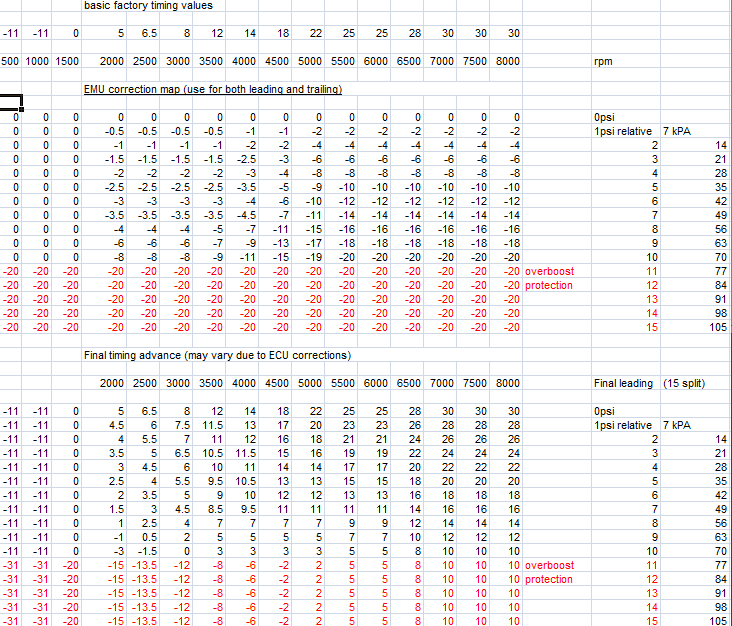
On the very top line is the Rx-8 commanded spark table when the engine gets into boost. The factory timing maps are not scaled for the additional loads of a turbocharged engine. The middle part of the spreadsheet is the E-Manage Ultimate correction map I built based on rpm and boost. The bottom part shows what the new timing values should be (might vary a bit) at these rpm and boost levels. The EMU maxes out at 20 degrees spark retard. Note that I am using 15 degrees split just like the factory Rx-8 timing maps.
If you look across the spark correction map, you'll see that I progressively ramped up the rate of spark retard over the rpm range. The result is a much "flatter" timing curve. The reason for this is because the engine doesn't need as much timing correction in the low rpm range, and pulling too much timing will hurt spool.
This Emanage timing correction map fixed the knocking problem on the Rx-8 in question. On an FC with an Rtek 2.1 or a standalone the timing maps are way less bullshit... that E-Manage Ultimate correction map was a lot of work. I had to locate the factory load-based timing map, create a boost-based ignition correction map, and then blend it together to figure out a resulting boost-based timing map. Controlling timing with a piggyback is a pain, avoid it if you can. And to make matters worse, Greddy reversed the leading and trailing wiring and their respective maps. So the leading correction map actually controlled the trailing and the trailing controlled the leading. If someone doesn't pick up on that the results could be disastrous.
I've been helping a couple guys with Greddy 18G kits. The factory Greddy emanage base map is a piece of ****. The timing maps make no sense and basically do nothing as far as retarding timing to compensate for the boost. So here is what happened to one guy who used the default Greddy map:
At 5500rpm the engine detonated pretty bad. The factory timing maps called for about 26 degrees leading with 15 split, which is just too much for 10:1 compression and a boosted setup. Luckily the Rx-8 PCM is smart enough to severely pull timing and the engine survived. In this case the engine was running about 7psi boost (spring pressure) on a Greddy TD06-18G with I believe the 10cm^2 hotside.
Because the emanage is a piggyback, I had to build correction maps relative to the factory commanded spark advance curve. I had to take the stock Rx-8 load based timing map (where the load columns max out, b/c Rx-8 isn't designed for boost) and then use a spreadsheet to figure out the correction I wanted. So check this out:
On the very top line is the Rx-8 commanded spark table when the engine gets into boost. The factory timing maps are not scaled for the additional loads of a turbocharged engine. The middle part of the spreadsheet is the E-Manage Ultimate correction map I built based on rpm and boost. The bottom part shows what the new timing values should be (might vary a bit) at these rpm and boost levels. The EMU maxes out at 20 degrees spark retard. Note that I am using 15 degrees split just like the factory Rx-8 timing maps.
If you look across the spark correction map, you'll see that I progressively ramped up the rate of spark retard over the rpm range. The result is a much "flatter" timing curve. The reason for this is because the engine doesn't need as much timing correction in the low rpm range, and pulling too much timing will hurt spool.
This Emanage timing correction map fixed the knocking problem on the Rx-8 in question. On an FC with an Rtek 2.1 or a standalone the timing maps are way less bullshit... that E-Manage Ultimate correction map was a lot of work. I had to locate the factory load-based timing map, create a boost-based ignition correction map, and then blend it together to figure out a resulting boost-based timing map. Controlling timing with a piggyback is a pain, avoid it if you can. And to make matters worse, Greddy reversed the leading and trailing wiring and their respective maps. So the leading correction map actually controlled the trailing and the trailing controlled the leading. If someone doesn't pick up on that the results could be disastrous.