
Engineering Project: PP 13B - comments? suggestions?

Thread Starter
FTD Wanna Be
Joined: Jun 2002
Posts: 1,252
Likes: 0
From: Virginia
Engineering Project: PP 13B - comments? suggestions?
I'm in my senoir year at Virginia Commonwealth University as a Mechanical Engineer and I thought some of you guys might be able to help with my senoir design project. The design phase of the project started this September and ends tommorrow when I turn in the final design report. The building phase of the project starts January '04 and ends May '04. Although we've finished the design report, we certainly won't stop designing and revising, so any suggestions will help a ton.
It's called 'Optimization of rotary engine intake timing, intake runners, exhaust headers, and variable length intake runner design using mathematical models.' I've posted the report for those who dare.
http://www.zaxjax.com/ModRX7_Design%20Documents.htm
We're building a peripheral port engine with a variable length intake, similar to the 787B. This is the main website. A few design drawings and other info: http://www.zaxjax.com/VCU_Racing.htm
The things I'm concerned with are:
-Ignition: Will the 12A distributor and coil setup work?
-Fuel delivery: We plan to use the 48IDA, but will it work just the same if we place it in-line with the lower intake manifold?
-Intake runner length: Our numbers seem to be too large. What is the average length? Typically I've seen around 8" from forum searching.
There are a few other things that I was worried about, but my brain is fried for tonight.
Thanks in advance!
all aboard!
Joined: Mar 2001
Posts: 1,204
Likes: 1
From: Houston
From what I read of the report I have one thought to share on the subject of the exhaust pulses moving through the header: What will the newest pressure wave do when it hits the exhaust gases from the previous cycle and how will that affect your desired runner length?
I'll come back and read the whole report when I'm better rested.
I'll come back and read the whole report when I'm better rested.


Joined: Mar 2001
Posts: 31,851
Likes: 3,238
From: https://www2.mazda.com/en/100th/
the 12a dizzy will work fine
the ida will too, i suggest the placement be part of your experimant, after all it is an interacting part of the intake.
my question to you is what are you optimising the intake for? power? economy? what rpm band? broad curve?
mike
the ida will too, i suggest the placement be part of your experimant, after all it is an interacting part of the intake.
my question to you is what are you optimising the intake for? power? economy? what rpm band? broad curve?
mike
Thread Starter
FTD Wanna Be
Joined: Jun 2002
Posts: 1,252
Likes: 0
From: Virginia
The exhaust pulse will return before the next pulse is created, so there will be no interaction between pulses. If you take the total exhaust open duration and time the pulse to return before it closes the next pulse will start after. Also, the pressure wave is always moving the exhaust out of the engine, so an interaction of waves would most likely cause constructive interference rather than cancellation.
I'm glad the 12A ignition will work, I was a little worried. We're going for a broad powerband with the variable length intake. I'm hoping for lots of power between 5000 and 8500. I don't want it to feel like a dud at low rpm. I've read that the square port style closes the power range slightly, so the intake pulse tuning effect should help out.
I'm glad the 12A ignition will work, I was a little worried. We're going for a broad powerband with the variable length intake. I'm hoping for lots of power between 5000 and 8500. I don't want it to feel like a dud at low rpm. I've read that the square port style closes the power range slightly, so the intake pulse tuning effect should help out.
Thread Starter
FTD Wanna Be
Joined: Jun 2002
Posts: 1,252
Likes: 0
From: Virginia
I think this illustration sums up the force of positive and negative pressure waves as they move through the runner. Paul Yaw explains it with the wake analogy to a moving boat. A wake caused by another boat (pressure change) travels outward and applies a force on another boat as it passes by. The wake eventually passes the second boat, but not without moving it slightly.
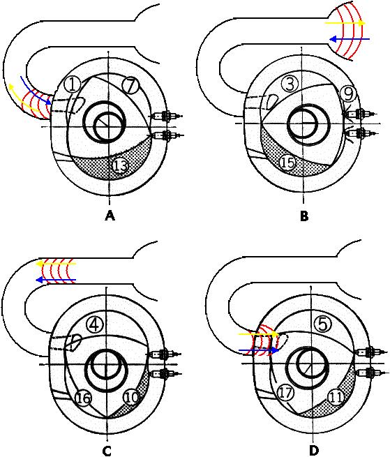
Yellow arrow is pulse direction, blue arrow is force direction. A negative pressure pulse forces molecules in the opposite direction of travel.
Yellow arrow is pulse direction, blue arrow is force direction. A negative pressure pulse forces molecules in the opposite direction of travel.

Undercover
Joined: Aug 2001
Posts: 1,983
Likes: 0
From: Ohio
I read the report and it sounds pretty good. Just one question though. I was looking at your intake runner leangths, is it just me or do they seem really long? most guys run manifold leangths of around 5-8 inches. your calculations yielded leangths of like over 20??? your headers leangths sound good though. definetly keep us updated on this. I think i might be building another 13bpp here within the next couple weeks over my christmas break so i may post up some pictures.
CJG
CJG
50mpg - oooooh yeah!
Joined: Mar 2003
Posts: 527
Likes: 0
From: UK
The length all depends on the port timing, so if you have a HUGE port time, then you'll have a pretty long inlet.
But how are you hoping to actuate the variable inlets? I was thinking about this the other day, and came across the idea of something like a modified electric aerial gearing - so it works quicker, but it also gives you that flexible peice of plastic-type-stuff to use as an actuator
But how are you hoping to actuate the variable inlets? I was thinking about this the other day, and came across the idea of something like a modified electric aerial gearing - so it works quicker, but it also gives you that flexible peice of plastic-type-stuff to use as an actuator
Trending Topics
Thread Starter
FTD Wanna Be
Joined: Jun 2002
Posts: 1,252
Likes: 0
From: Virginia
The lengths do seem too long to me, but the ports are open for a long time. At 9,000 RPM I found that 24" was ideal, which is 3 times what most people use. I don't think my port design is 3 times longer than most PP engines!
Chairchild, check out the drawings on the pictures page of this website:
http://www.zaxjax.com/VCU_Racing.htm
I posted two designs for the VLI. We're probably going to use the cable design.
Chairchild, check out the drawings on the pictures page of this website:
http://www.zaxjax.com/VCU_Racing.htm
I posted two designs for the VLI. We're probably going to use the cable design.

Full Member
Joined: Jul 2001
Posts: 75
Likes: 0
From: Rockford, IL
I have a few comments:
1. The speed of sound in air is a function of temperature (temperature only, not pressure, ref. ideal gas law). With this said, the speed of air at 70�F is approximately 13535 in/sec, which is close enough to the 1320 in/sec number you are using. At 1500�F, (typical exhaust temps under heavy load) the speed of air is approximately 26047 in/sec. I realize this is for air, not exhaust gas (which has a different composition) but I do believe your 1320 in/sec number is quite a bit low for the exhaust gas timing.
2. If you assume that the speed of the exhaust gases is close to that of air at 1500�F, your exhaust header lengths are 50% too long. Oddly enough, you already reduced the header lengths by .4 -.5x based on time to peak exhaust pulse amplitude (?).
3. Refractory waves are not setup by peak wave amplitude. They are initiated the instant the rotor begins to expel or intake air.
4. I have to think about this some more, but I believe that reducing the intake runner length by .4 - .5x is advantageous, in that the negative pulse arrives before peak intake amplitude (having little affect because the intake suction is so strong) and the second positive pulse arrives near port closing to force more air in.
5. I there is intake to exhaust overlap, the exhaust negative pulse should be timed to arrive right before exhaust port closing to cram intake air (pulled out the exhaust port by the positive wave) back into the intake cycle.
Hope some of this helps.
Glenn
'93 CYM
Thread Starter
FTD Wanna Be
Joined: Jun 2002
Posts: 1,252
Likes: 0
From: Virginia
I knew the exhaust speed of sound was off, but I ignored it for the time being because we waited till the last minute to write the paper! I didn't know it is 26047in/sec, so that definately helps.
So my exhaust header lengths are right, but because the speed I used is half what it should be, not because of the peak amplitude theory.
Your suggesting to half the intake runner length from 24" min. to 12" min., or are you saying the peak amplitude theory (0.4-0.5x) takes care of that already, so 24" is correct?

Thread
Thread Starter
Forum
Replies
Last Post
cdn
2nd Generation Specific (1986-1992)
14
Sep 10, 2015 06:23 AM
cdn
2nd Generation Non-Technical and pictures
0
Aug 11, 2015 08:59 PM
KAL797
Test Area 51
0
Aug 11, 2015 03:47 PM