
25XP's X Prepared FC Rx7

 02-14-12, 10:18 PM
#78

do drop spindles exist? if so, then yes. the problem is the sway bar mounting location on the control arm get crazy high with respect to the bar mounts, so the bar rate is progressive, and binding the endlinks is an issue.
doing some kind of roll center kit will definately help. im still halfway done lol, havnt had time to do anything productive lately.
doing some kind of roll center kit will definately help. im still halfway done lol, havnt had time to do anything productive lately.
02-14-12, 11:37 PM
#79
Formerly known as 25BP
Thread Starter
Join Date: Oct 2011
Location: NorCal
Posts: 127
Likes: 0
Received 0 Likes
on
0 Posts


Here is another pic I have of the way the bar mounts on the upper rails. A bit more clearance in the holes, but a good look at how it mounts.
25XP
02-15-12, 08:48 AM
#80
Senior Member
Join Date: Jul 2005
Location: CA
Posts: 305
Likes: 0
Received 0 Likes
on
0 Posts
I recognize those legs! They belong to my brother in law
FWIW- That is a smaller Speedway Bar (1"?). We picked up a bunch of suspension stuff from an aborted EP project and that was the bar we got. Eventually we will get the thicker bar after we get the car sorted
FWIW- That is a smaller Speedway Bar (1"?). We picked up a bunch of suspension stuff from an aborted EP project and that was the bar we got. Eventually we will get the thicker bar after we get the car sorted
02-15-12, 07:32 PM
#82
Formerly known as 25BP
Thread Starter
Join Date: Oct 2011
Location: NorCal
Posts: 127
Likes: 0
Received 0 Likes
on
0 Posts
25XP
02-16-12, 03:59 PM
#84
Formerly known as 25BP
Thread Starter
Join Date: Oct 2011
Location: NorCal
Posts: 127
Likes: 0
Received 0 Likes
on
0 Posts
I pulled the new fuel system out from in/under the car to prep for painting. I decided to POR15 the underside of the car, as it was nasty and I simply couldn't put this killer fuel system back without some paint.
Here is a couple pics of the finished fuel system I will be running. The hardlines run up to the engine bay, and there are pics of it previously.
There are a lot of fittings to assure no leaks!
25XP
Here is a couple pics of the finished fuel system I will be running. The hardlines run up to the engine bay, and there are pics of it previously.
There are a lot of fittings to assure no leaks!
25XP
02-16-12, 04:11 PM
#85
Formerly known as 25BP
Thread Starter
Join Date: Oct 2011
Location: NorCal
Posts: 127
Likes: 0
Received 0 Likes
on
0 Posts
My new "storage bins".
I am no welder by any means, I know this and accept it, but the panels are secure and serve the purpose.
I will repaint the inside of the car shortly. After making the new bins, and removing the passenger seat mounts and rear speaker towers it needs some new paint.
There is a shot of the underside of the new bin, I POR15 the new panel, this is was the first coat, but it gives you a good idea of that the underside of the car will look like when I finish.
I had thought about POR15 the inside of the car with the gray that they have, but I really like the matching Artic siliver interior/exterior so I think it will stay.
25XP

 02-27-12, 11:49 PM
#89
Formerly known as 25BP
Thread Starter
Join Date: Oct 2011
Location: NorCal
Posts: 127
Likes: 0
Received 0 Likes
on
0 Posts
Lastly, what are the prices of AWR's kit.
Thanks for the info.
25XP
02-28-12, 02:36 AM
#90
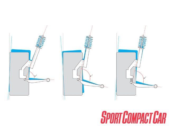
Swapping the ball joint to the top of the arm will not help with the roll center (though I have done it).
The roll center geometry is set by forming and angle using a line perpendicular to the strut angle at the pillow ball/bushing located on top of the strut and a line between the ball joint and lower arms bushing center. Now draw a line from that intersection to the contact patch and the roll center will be along that line where it meets the vehicle center line.

I believe what swapping the ball joint can do is regain a little downward angle of the arm from the chassis to the end link so that on initial compression the arm moves to parallel to the ground and the end link is now at the furthest point from the chassis in its arc so gaining a tiny bit of negative camber (just before losing it as the arc continues).
The roll center geometry is set by forming and angle using a line perpendicular to the strut angle at the pillow ball/bushing located on top of the strut and a line between the ball joint and lower arms bushing center. Now draw a line from that intersection to the contact patch and the roll center will be along that line where it meets the vehicle center line.
I believe what swapping the ball joint can do is regain a little downward angle of the arm from the chassis to the end link so that on initial compression the arm moves to parallel to the ground and the end link is now at the furthest point from the chassis in its arc so gaining a tiny bit of negative camber (just before losing it as the arc continues).
 02-28-12, 08:25 AM
#92
yeah, moving the stock ball joint around doesn't do anything. Many people intuitively go down that path with poor results.
Mainly because the actual imaginary arm is a line that goes from the pivot through the center of the ball joint. you can move the mount all you want, but the ball join is still going to be right underneath the knuckle where it's always been. If anything you're just changing the length of that arm slightly.
The price is about $400 for the roll center kit (ball joint) and $200 for the bump steer correction (tie rods) which is about the same as I paid for a very similar kit on my corolla.
I just wish he spaced it down a little more... but he might have run into problems running into the brake discs or something.
02-29-12, 05:26 PM
#94
Damn those ball joints were EXACTLY what i had planned to make myself as soon as i get my hands on a lathe to make the ball joint pins. I can only find tapered pins in aftermarket applications, and really didn't want weld and taper out the ball joint hole on the spindle.
ALso agree on placing the joint above does nothing since the pivots are exactly the same, all that is being done is lowering the control arm closer to the ground.
ALso agree on placing the joint above does nothing since the pivots are exactly the same, all that is being done is lowering the control arm closer to the ground.
03-01-12, 02:57 AM
#95
Formerly known as 25BP
Thread Starter
Join Date: Oct 2011
Location: NorCal
Posts: 127
Likes: 0
Received 0 Likes
on
0 Posts
Great info about AWR's new products, THANKS.
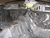
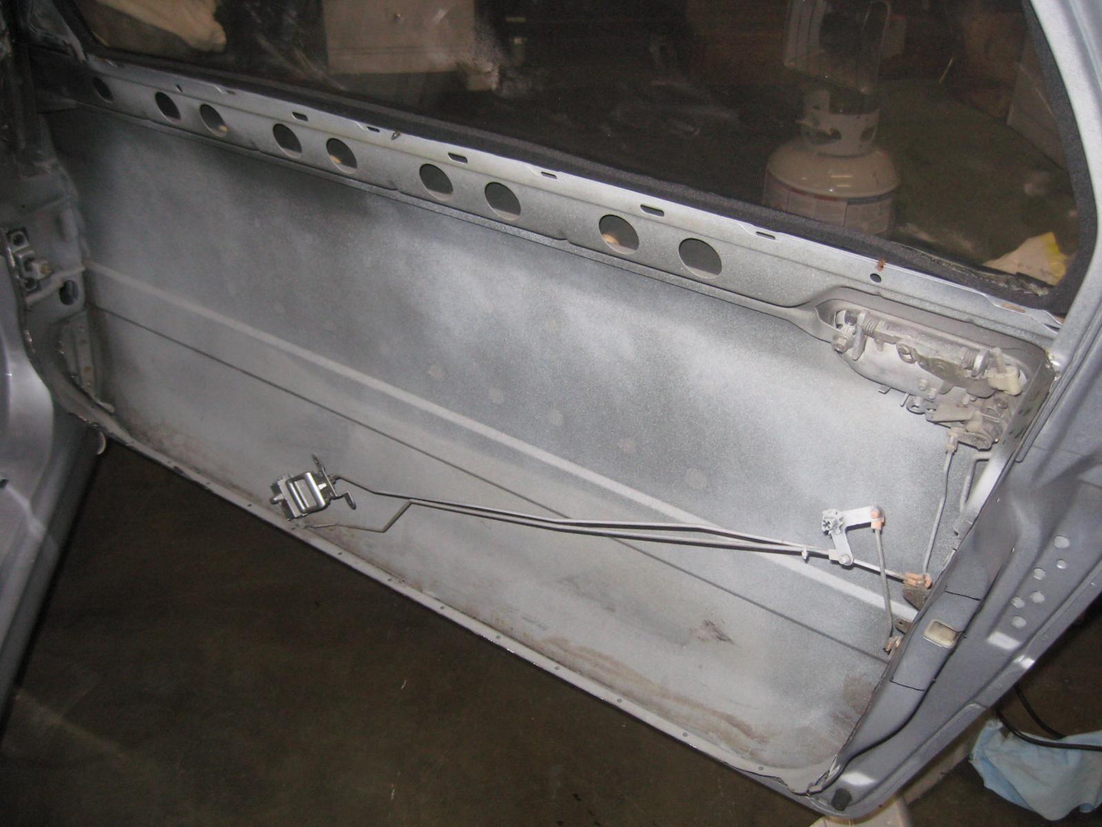
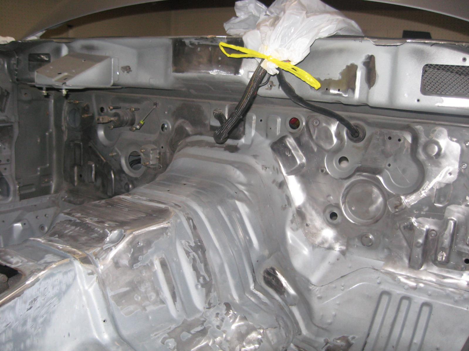
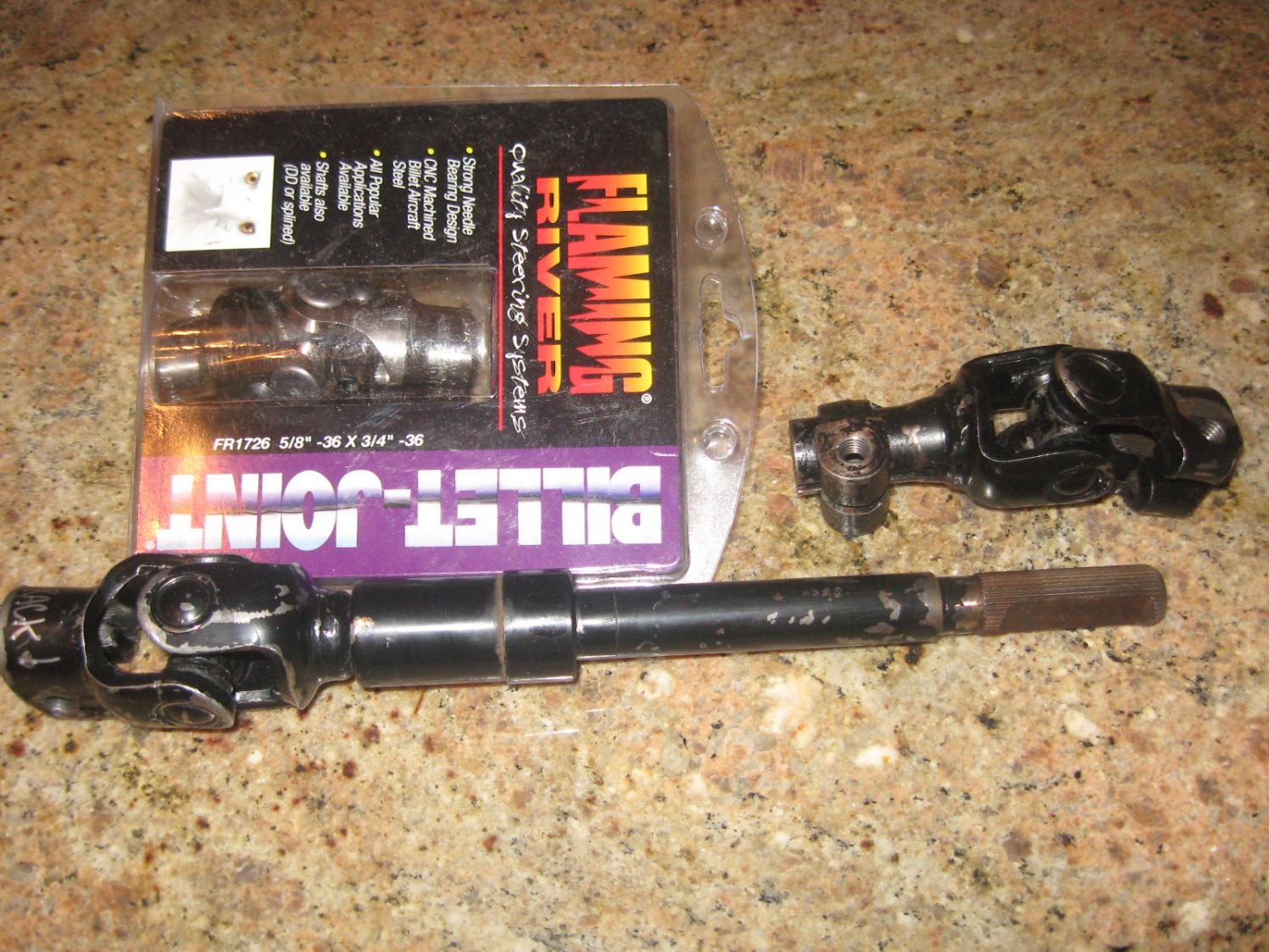
My doors were already trimmed down and had the supports removed. In my quest to get the cars weight down to the bare minimum. I removed the aluminum panel covers and trimmed the doors down to the bare minimum. I still have the ablility to mount the lexan side windows for towing and bad weather. I will figure how I want to open the doors from the inside, something simple.

Also you can all the extra tabs and brackets removed from the front the dash.
25XP
My doors were already trimmed down and had the supports removed. In my quest to get the cars weight down to the bare minimum. I removed the aluminum panel covers and trimmed the doors down to the bare minimum. I still have the ablility to mount the lexan side windows for towing and bad weather. I will figure how I want to open the doors from the inside, something simple.
Also you can all the extra tabs and brackets removed from the front the dash.
25XP
03-01-12, 03:28 AM
#96
Formerly known as 25BP
Thread Starter
Join Date: Oct 2011
Location: NorCal
Posts: 127
Likes: 0
Received 0 Likes
on
0 Posts
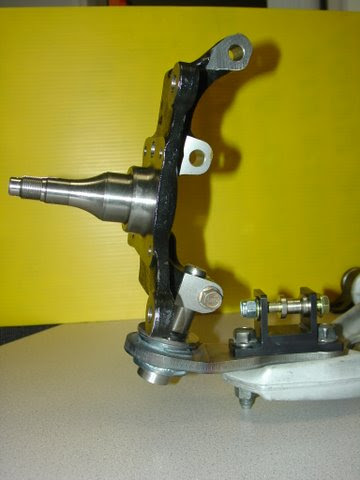
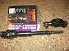
I am looking for some clarification on a S4 power steering rack spline size. The spline on the shaft shown in the picture on the right. That shaft is from the PS rack to the steering column.
I measured it and I thought it was 5/8- 36 spline. I ordered a steering joint in that size and it does not fit.
Stamped on the new steering joint it states: 625/36. The package states: 5/8- 36 spline, so I assume it is packaged correctly. Also before anyone states it, yes I know the other end of the joint in the picture is 3/4- 36.
That being said, does anyone know what the factory spline is if not 5/8- 36.
Thanks,
25XP
03-01-12, 06:36 AM
#97
Formerly known as 25BP
Thread Starter
Join Date: Oct 2011
Location: NorCal
Posts: 127
Likes: 0
Received 0 Likes
on
0 Posts
I found the answer, it seems that Miata's also carry the same spline count.
.625-23/36 appears to be the correct spline. It has 13 teeth removed, hence the 625-23. 13 teeth less than 36 and you get your 23. I assume it is for clocking the joints. Mazda can't make it simple, can they...
In the end, I think I found the solution to my problem, it is just going to take some more parts.
Hope it helps,
25XP
03-01-12, 07:20 PM
#98
Moderator
iTrader: (3)
Join Date: Mar 2001
Location: https://www2.mazda.com/en/100th/
Posts: 31,121
Received 2,786 Likes
on
1,972 Posts
03-01-12, 10:02 PM
#99
trying to build a racecar
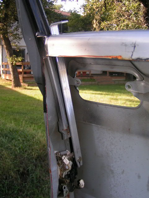
Here's what i did. Just push down on the horizontal part and it pops open. Not sure if it'll work with the outside latch still in place though. Made from 1/8" aluminum strip.
03-01-12, 10:26 PM
#100
Formerly known as 25BP
Thread Starter
Join Date: Oct 2011
Location: NorCal
Posts: 127
Likes: 0
Received 0 Likes
on
0 Posts
Travis,
That looks great, simple and easy. I probably will do something similar.
Although I am shaving as much weight from the car, I can not give up locking the door and keeping the outside handle.
Thanks for the picture, idea.
25XP
That looks great, simple and easy. I probably will do something similar.
Although I am shaving as much weight from the car, I can not give up locking the door and keeping the outside handle.
Thanks for the picture, idea.
25XP