Power FC Forum Apex Power FC Support and Questions.

Power FC PowerFC LCD Tweak.

Thread Tools
 
Search this Thread
 
Old 08-31-19, 11:45 AM
  #101  
Mazdaspeed addict

iTrader: (7)
 
kulluminati777's Avatar
 
Join Date: Jul 2013
Location: Dallas
Posts: 282
Received 10 Likes on 9 Posts
Originally Posted by Str3atWarrior
I started offering LCD replacement as a service on various facebook pages, did around 15 so far and everybody is pleased with them! Should i make a post here to offer the service? Would anybody be interested?
I would be interested for sure
Old 08-31-19, 12:33 PM
  #102  
Full Member

iTrader: (1)
 
Str3atWarrior's Avatar
 
Join Date: Jun 2014
Location: Montreal, Canada
Posts: 223
Likes: 0
Received 25 Likes on 18 Posts
I just made a post about the service, see infos, and pm me if you're interested!
Old 09-07-19, 04:54 PM
  #103  
Eric Seven
 
tomatoto's Avatar
 
Join Date: Apr 2018
Location: France
Posts: 276
Received 32 Likes on 22 Posts
Hey there
I've bought a ks108 compatible display ( linked above, reference : LCD-AG-128064H-DIW W/KK-E6 ) and soldered it today. I used a rotary potentiometer between pin 2 and 3, in order to find the right resistance... But I only have a full dark screen ( it's a black background screen)...
Maybe some of you had the same problem and found a fix ?
I'm not 100% sure if the 18th pin is totally 'disconnected' (I didnnt understand if the track to cut is on the screen board or on the main board), but if it's not disconnected, could it explain my problem?


Last edited by tomatoto; 09-07-19 at 05:55 PM.
Old 09-08-19, 04:52 AM
  #104  
Full Member

iTrader: (1)
 
Str3atWarrior's Avatar
 
Join Date: Jun 2014
Location: Montreal, Canada
Posts: 223
Likes: 0
Received 25 Likes on 18 Posts
Post the pinout of your lcd
Old 09-08-19, 05:36 AM
  #105  
Eric Seven
 
tomatoto's Avatar
 
Join Date: Apr 2018
Location: France
Posts: 276
Received 32 Likes on 22 Posts
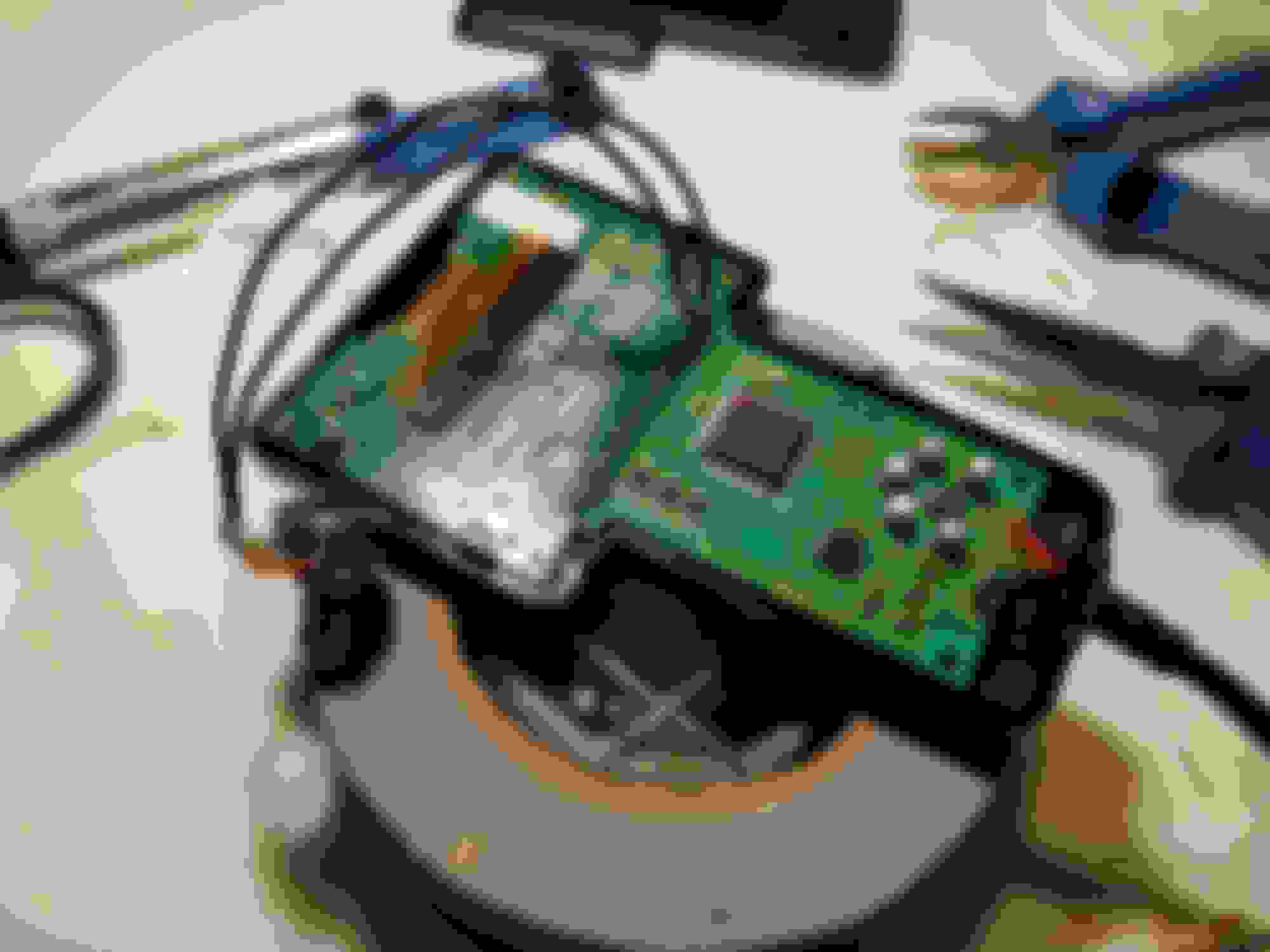
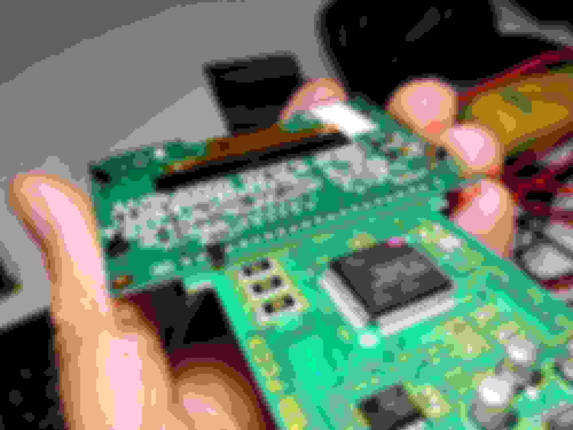
The pinout ? I didn't have any documentation with the screen.. I'll attach photos of both side
I actually just tried to unsolder the screen this morning, I struggled quite a lot and then I forced it too much and teared out many dots.. now I'm sure I fucked up both the main board and the screen... Damnit 😭 gotta find a spare commander somewhere...


Last edited by tomatoto; 09-08-19 at 05:55 AM.
Old 09-08-19, 09:36 AM
  #106  
Full Member

iTrader: (1)
 
Str3atWarrior's Avatar
 
Join Date: Jun 2014
Location: Montreal, Canada
Posts: 223
Likes: 0
Received 25 Likes on 18 Posts
Want me to check it? If you send it to me i can check if it's fixable
Old 09-17-19, 03:53 PM
  #107  
Rexxy

iTrader: (40)
 
Jose A.'s Avatar
 
Join Date: Mar 2009
Location: Glendale, AZ
Posts: 1,247
Likes: 0
Received 7 Likes on 6 Posts
Question

Originally Posted by Str3atWarrior
I just made a post about the service, see infos, and pm me if you're interested!
Do you have a link to order the blue lcd? I need to do mine but not sure what would work. I have a lcd and also oled commander, but both are dim already lol.
Old 09-20-19, 11:11 AM
  #108  
Full Member

iTrader: (1)
 
Str3atWarrior's Avatar
 
Join Date: Jun 2014
Location: Montreal, Canada
Posts: 223
Likes: 0
Received 25 Likes on 18 Posts
Can't just give you my supplier, hope you understand... But lots of infos on this thread, if you want to try and order some. I still offer the replacement service if you want me to do it, i currently have 6 in stock
Old 09-22-19, 11:26 AM
  #109  
Junior Member
 
Fraz McLennan's Avatar
 
Join Date: Mar 2019
Location: UK
Posts: 40
Received 0 Likes on 0 Posts
Sometimes I get it working, sometimes I get it with the blank screen. When you press the buttons the picture goes wonky. Any ideas? I'm thinking I may have not removed pin 18 enough and sometimes is making a connection. Anyone agree with this or do I have other issues? Screen is a known working screen as someone previously used the same screen and said it worked.

Also it says you can ground pin 18. Could I just run a tiny wire to the GND on the other side of the board?


Last edited by Fraz McLennan; 09-22-19 at 02:43 PM.
Old 09-22-19, 02:28 PM
  #110  
Full Member

iTrader: (1)
 
Str3atWarrior's Avatar
 
Join Date: Jun 2014
Location: Montreal, Canada
Posts: 223
Likes: 0
Received 25 Likes on 18 Posts
I never ground pin 18. Seems like your resistance between 2-3 is not soldered correctly
Old 09-22-19, 02:29 PM
  #111  
Full Member

iTrader: (1)
 
Str3atWarrior's Avatar
 
Join Date: Jun 2014
Location: Montreal, Canada
Posts: 223
Likes: 0
Received 25 Likes on 18 Posts
For that matter i only remove the pin from pin18 and the solder with a solder wick. I dont cut trace, never had a problem
Old 09-22-19, 02:42 PM
  #112  
Junior Member
 
Fraz McLennan's Avatar
 
Join Date: Mar 2019
Location: UK
Posts: 40
Received 0 Likes on 0 Posts
Originally Posted by Str3atWarrior
For that matter i only remove the pin from pin18 and the solder with a solder wick. I dont cut trace, never had a problem
Nice one mate will try re doing the resistor. Never soldered a SMD resistor in before, seems it's quite tricky.
Old 09-22-19, 07:58 PM
  #113  
Full Member

iTrader: (1)
 
Str3atWarrior's Avatar
 
Join Date: Jun 2014
Location: Montreal, Canada
Posts: 223
Likes: 0
Received 25 Likes on 18 Posts
You could use a normal one too, 470ohm does the trick. I use smd because it looks cleaner, even tho nobody will ever see it ???♂
Old 09-23-19, 12:47 AM
  #114  
Junior Member
 
Fraz McLennan's Avatar
 
Join Date: Mar 2019
Location: UK
Posts: 40
Received 0 Likes on 0 Posts
Originally Posted by Str3atWarrior
You could use a normal one too, 470ohm does the trick. I use smd because it looks cleaner, even tho nobody will ever see it ???♂
Fair one, I take it I can just use the resistor legs as the pins then?
Old 09-23-19, 10:08 AM
  #115  
Full Member

iTrader: (1)
 
Str3atWarrior's Avatar
 
Join Date: Jun 2014
Location: Montreal, Canada
Posts: 223
Likes: 0
Received 25 Likes on 18 Posts
You could, or just solder the pin's end to the other pins,cut to fit
Old 09-24-19, 11:41 AM
  #116  
Full Member

iTrader: (1)
 
Str3atWarrior's Avatar
 
Join Date: Jun 2014
Location: Montreal, Canada
Posts: 223
Likes: 0
Received 25 Likes on 18 Posts
I included pictures to give you an heads up on how i do it. And no cut on pin 18, just by removing solder and pin


Old 10-06-19, 06:23 AM
  #117  
Junior Member
 
Fraz McLennan's Avatar
 
Join Date: Mar 2019
Location: UK
Posts: 40
Received 0 Likes on 0 Posts
Originally Posted by Str3atWarrior
I included pictures to give you an heads up on how i do it. And no cut on pin 18, just by removing solder and pin

Just had a go at it with normal resistors. The 470 ones
had the same effect, no image on the screen. I think tried wiring 2 in series and the screen was very bright (still no image). I then tried parallel and it was much darker but again no image.

At this point I'm not not sure how it has even worked before in the first place.
Old 10-06-19, 09:14 AM
  #118  
Full Member

iTrader: (1)
 
Str3atWarrior's Avatar
 
Join Date: Jun 2014
Location: Montreal, Canada
Posts: 223
Likes: 0
Received 25 Likes on 18 Posts
Originally Posted by Fraz McLennan
Just had a go at it with normal resistors. The 470 ones
had the same effect, no image on the screen. I think tried wiring 2 in series and the screen was very bright (still no image). I then tried parallel and it was much darker but again no image.

At this point I'm not not sure how it has even worked before in the first place.
Post a picture of the screen you used and your soldering on both sides, i'll try and see if i can spot something wrong for you.
Old 10-06-19, 10:02 AM
  #119  
Junior Member
 
Fraz McLennan's Avatar
 
Join Date: Mar 2019
Location: UK
Posts: 40
Received 0 Likes on 0 Posts
Originally Posted by Str3atWarrior
Post a picture of the screen you used and your soldering on both sides, i'll try and see if i can spot something wrong for you.
Hopefully you spot something I haven't. I will also say I did original pin pin 18 but removed it. Maybe that's what's causing the issues.


Old 10-06-19, 12:53 PM
  #120  
Full Member

iTrader: (1)
 
Str3atWarrior's Avatar
 
Join Date: Jun 2014
Location: Montreal, Canada
Posts: 223
Likes: 0
Received 25 Likes on 18 Posts
Your soldering seems spot on. I'm not home so i can't compare pinout right now. My guess would be defective LCD. I got a defective one that would display garbage out of all the ones i bought, always from the same distributor. I sent a picture to the seller to inform him, he offered to replace it, which i declined. I know their margin of profit is minimal and they ship fast, are a reliable supplier so no way i'd risk all that over a defect. The last two batch i ordered have been bubble wrapped individually
Old 10-06-19, 01:12 PM
  #121  
Junior Member
 
Fraz McLennan's Avatar
 
Join Date: Mar 2019
Location: UK
Posts: 40
Received 0 Likes on 0 Posts
Originally Posted by Str3atWarrior
Your soldering seems spot on. I'm not home so i can't compare pinout right now. My guess would be defective LCD. I got a defective one that would display garbage out of all the ones i bought, always from the same distributor. I sent a picture to the seller to inform him, he offered to replace it, which i declined. I know their margin of profit is minimal and they ship fast, are a reliable supplier so no way i'd risk all that over a defect. The last two batch i ordered have been bubble wrapped individually
Fair one. Any chance of DMing me a link to a quality supplier? Waited nearly 2 months for this one to arrive.
Old 10-06-19, 08:50 PM
  #122  
Full Member

iTrader: (1)
 
Str3atWarrior's Avatar
 
Join Date: Jun 2014
Location: Montreal, Canada
Posts: 223
Likes: 0
Received 25 Likes on 18 Posts
Originally Posted by Fraz McLennan
Fair one. Any chance of DMing me a link to a quality supplier? Waited nearly 2 months for this one to arrive.
Can't really give you my supplier for obvious reason... But if you want me to replace your LCD hit me up!
Old 10-07-19, 01:00 AM
  #123  
Junior Member
 
Fraz McLennan's Avatar
 
Join Date: Mar 2019
Location: UK
Posts: 40
Received 0 Likes on 0 Posts
Originally Posted by Str3atWarrior
Can't really give you my supplier for obvious reason... But if you want me to replace your LCD hit me up!
Fair one mate entirely understandable. Many thanks for the help anyways mate. Will try order another and see what happens. Failing that....
Old 10-07-19, 07:15 AM
  #124  
Full Member

iTrader: (1)
 
Str3atWarrior's Avatar
 
Join Date: Jun 2014
Location: Montreal, Canada
Posts: 223
Likes: 0
Received 25 Likes on 18 Posts
Originally Posted by Fraz McLennan
Fair one mate entirely understandable. Many thanks for the help anyways mate. Will try order another and see what happens. Failing that....
Check your pm
Old 10-17-19, 06:11 AM
  #125  
Full Member

iTrader: (1)
 
Str3atWarrior's Avatar
 
Join Date: Jun 2014
Location: Montreal, Canada
Posts: 223
Likes: 0
Received 25 Likes on 18 Posts
By the way, for the SMD led, the original size is 0805. I bought some 1206 and some 0805, 1206 can be made to work but are really flush with the soldering pads. 0805 is the way to go. Be advised that it does require some skill to solder in place without lifting pads or breaking anything.


Quick Reply: Power FC PowerFC LCD Tweak.


All times are GMT -5. The time now is 06:34 AM.