
Little question for my transverse project


Thread Starter
Bart
Joined: Dec 2004
Posts: 78
Likes: 0
From: the Netherlands
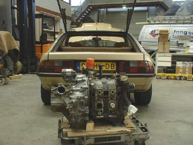
Not much happened the last months. I have the final adapter plate and engine mounts ready. I am still not sure how make the drive shaft bearing. I will find out when i am trail fit the engine. But to trail fit the engine means i have to take the old engine out. And i want to do that not yet. I need the car to go on holiday in september and in august it must be MOT tested (with old engine). But lots of other things to do before trail fitting is nescessary.

When the drive shaft is in place, the only way to mount the header is to slide it on the bottem bolts.
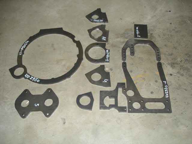
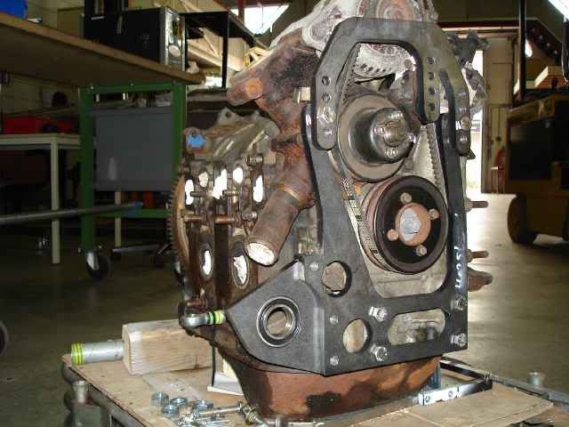
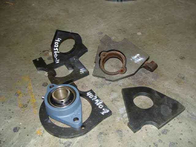
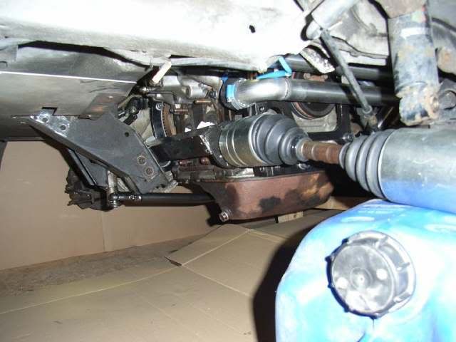
About the drive shaft bearing: I had several options made. The third picture shows the easyest. But i also had other mounts made. So at trail fitting i decide which one i take. It all depents on if the engine will fit where i want it to be. If it fits where i want it to be, then i need the mount which needs drilling in the front-iron. If the engine needs to be moved, i need one of the other mounts.
When the drive shaft is in place, the only way to mount the header is to slide it on the bottem bolts.
About the drive shaft bearing: I had several options made. The third picture shows the easyest. But i also had other mounts made. So at trail fitting i decide which one i take. It all depents on if the engine will fit where i want it to be. If it fits where i want it to be, then i need the mount which needs drilling in the front-iron. If the engine needs to be moved, i need one of the other mounts.
Very nice work. Again from curiosity: what about the axle support makes it necessary to drill into the front iron? It seems to me that the load on the bearing would be in an up/down direction as viewed from the front of the engine, not in/out, meaning the support in the third picture would work without resorting to drilling into the iron and adding rear bracing. Or am I missing something completely?
That bracket looks plenty strong; only thing I would recommend is welding the bearing carrier to the main support rather than bolting to prevent shifting and misalignment.
Again, very nice work and best of luck to you.
That bracket looks plenty strong; only thing I would recommend is welding the bearing carrier to the main support rather than bolting to prevent shifting and misalignment.
Again, very nice work and best of luck to you.
Thread Starter
Bart
Joined: Dec 2004
Posts: 78
Likes: 0
From: the Netherlands
This size of the driveshaft (wheel-CVjoint-axle-CVjoint-bearing) determs the position of the bearing. If i have to move the engine a bit to the right, the bearing has to move a bit left to stay in the same postion regarding to the wheel.
The front iron drilling is needed when i place the engine in like i plan to do. But my tapemeasure tells me that it wiil be a very very tight fit. I probably have to move the engine a bit.
The driveshaft wil be a joined toyota/matra shaft. The connection is between the bearing and the dif.
The front iron drilling is needed when i place the engine in like i plan to do. But my tapemeasure tells me that it wiil be a very very tight fit. I probably have to move the engine a bit.
The driveshaft wil be a joined toyota/matra shaft. The connection is between the bearing and the dif.
Last edited by bart_heemskerk; Jul 11, 2006 at 06:09 AM.
Hmmm. I'm not looking at it first hand, but my gut feeling is to shorten the right hand driveshaft or shift the engine slightly to the left rather than drill into the iron or move the bearing. Since it's mid engine, torque steer from different shaft lengths won't be a problem.
I did the hybrid driveshaft thing recently on the Abomination (rotary Spitfire). It can be done pretty easily, in my case the second version (first uninformed version did not go very well) was to drill a pilot hole in each driveshaft half, use a corresponding diameter rod for alignment, taper the end of the halves and then weld them together, filling the taper as I went. I then used some 4140 steel tubing split lengthwise (so I could put it over the shaft, the splines are bigger than the driveshaft) and drilled through for 'plug welding' which was then clamped to the hybrid shaft over the welded area, plug welded, the splits were then welded, then circle welded at the ends of the tubing.
After that, I heated the shafts for a few hours until they were just starting to glow dull red, and then buried them in oil dry (fullers' earth) so that they would cool slowly. The shafts made all kinds of popping and clicking noises during that part, as the internal stresses were relieved! So far, so good. Repeated hard autocross launches with sticky race tires haven't caused a problem.

Thread Starter
Bart
Joined: Dec 2004
Posts: 78
Likes: 0
From: the Netherlands
Very close to completion now!
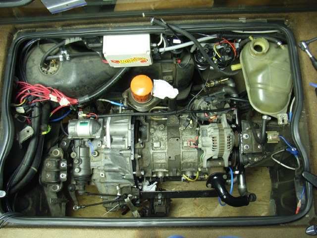
Completed so far:
12A mounted to a toyota tranny with an adapter plate, enginemounts, driveshafts, driveshaft-bearing on block, header, cooling tubes, gearshift levers, hydraulic clutch, wiring loom, and so on..
Also done:
rats nest removal and OMP mod.
Still to do:
small fidely stuff...
Completed so far:
12A mounted to a toyota tranny with an adapter plate, enginemounts, driveshafts, driveshaft-bearing on block, header, cooling tubes, gearshift levers, hydraulic clutch, wiring loom, and so on..
Also done:
rats nest removal and OMP mod.
Still to do:
small fidely stuff...
Thread Starter
Bart
Joined: Dec 2004
Posts: 78
Likes: 0
From: the Netherlands
Driveshaft bearing is made as discussed before.
It is mounted to a piece of metal which is bolted to the front enginemount and with one bolt in the front iron. Yes, i've drilled one hole in the front iron.\
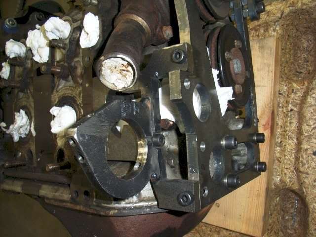
It is mounted to a piece of metal which is bolted to the front enginemount and with one bolt in the front iron. Yes, i've drilled one hole in the front iron.\
Thread Starter
Bart
Joined: Dec 2004
Posts: 78
Likes: 0
From: the Netherlands
Some more pics
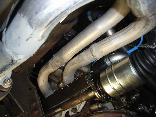
Righthand side driveshaft. And some stainless coolingpipes above driveshaft.
Header.
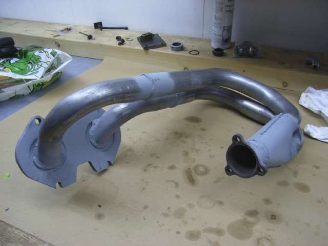
To get the header mounted i had to remove the two upper struts. I have cut out the lower holes so i can slide the header on the struts. The header is fixed by two normal bolts at the top. At the bottom there is just enough space to turn the nuts (driveshaft is very near by)
Righthand side driveshaft. And some stainless coolingpipes above driveshaft.
Header.
To get the header mounted i had to remove the two upper struts. I have cut out the lower holes so i can slide the header on the struts. The header is fixed by two normal bolts at the top. At the bottom there is just enough space to turn the nuts (driveshaft is very near by)
Rotary Enthusiast
Joined: Jan 2003
Posts: 1,349
Likes: 2
From: planet earth
Jongen je bet knettergek om dat te proberen !!, maar wel gaaf eenmaal als je het klaar hebt moet je een turbo proberen ,dat lijkt me super
Ziet er wel goed uit hoor , ik zou ook nooi denken dat het jouw zou lukken ,maar zo tezien gaat het je lukken ...en goed ook
Ziet er wel goed uit hoor , ik zou ook nooi denken dat het jouw zou lukken ,maar zo tezien gaat het je lukken ...en goed ook
Thread Starter
Bart
Joined: Dec 2004
Posts: 78
Likes: 0
From: the Netherlands
And here is the evidence!
You CAN fit an exhaust when having transverse drive shafts!
Actualy, this header is very easy to fit. I don't have to take extra parts on/off to fit it!
The car is driveable now
You CAN fit an exhaust when having transverse drive shafts!
Actualy, this header is very easy to fit. I don't have to take extra parts on/off to fit it!
The car is driveable now
Thread Starter
Bart
Joined: Dec 2004
Posts: 78
Likes: 0
From: the Netherlands
Question,
On the distributor, Which is Leading and which is Trailing?
EDIT: found the answer, facing the front is the leading, facing the alternator is trailing.
On the distributor, Which is Leading and which is Trailing?
EDIT: found the answer, facing the front is the leading, facing the alternator is trailing.
Last edited by bart_heemskerk; Mar 22, 2007 at 01:30 AM.
Thread Starter
Bart
Joined: Dec 2004
Posts: 78
Likes: 0
From: the Netherlands
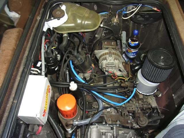
The bottle contains 2-stroke oil for the omp. It is an ordinairy softdrink bottle.
Driving it bringsback memories of the good old FB. I am so happy the sound of the rotary is back! The rotary engine is a bit heavier than the engine it replaced. About 10 kg. But the rotary engine is mounted a bit lower so the center of gravity is much lower. The body rolls quite a bit less. But the car is in need of new suspension. It should corner much better than it does now.
The gearchange is not very smooth. The toyota gearbox i used was an old worn item i got for free. I replaced all the synchromise rings. Maybe new rings has to wear in before i got smooth gearchange? Also i don't know what to do with the oil level in the gearbox. the box is a tiny bit tilted backwards. At the front of the gearbox is the filler hole. When the box is in the right position, the oil level should be 1mm below the filler hole. Which is equal to 2.6 litre.
I have put in 2.6 litre oil and because the box is tilted the level is appr. 10mm below the fillerhole. Should i put more oil in so the level is 1mm below fillerhole? I don't know. Has to find out.
There is also a lack of power when the secondairies opens. I think i blame the airfilter. i want to put in a new bigger one which sucks air from a coller place. I think it is also a good idea to clean the carb. Or maybe i did something wrong with the ratsnest removal. I thoke off all the solenoids and closed all the pipes on the manifold. I connected the ignition advancer with 2 tubes directly to the corresponding pipes on the manifold.
I am also not sure what to do with the richer-solenoid. I connected it to permanent 12volt.
So a few things to sort out. The next project will be megasquirt injection. It is already present in the car. The previous engine did run on it.
Glad you got it running!  Congratulations on a well thought out and professional looking swap.
My thought on the trans oil level: if you fill it to the 1mm point you are mentioning, will that cause it to be too deep at the input shaft? I mention this because I overfilled a Triumph transmission and it promptly started leaking from the input shaft seal. Bringing the oil to the correct level fixed that. I think you are on the right track by using the specified amount.
Poor shift quality: is it 'crunching' or just sloppy? Crunch = worn synchronizer assembly, sloppy = external shift linkage play. On my 914 Porsche, I found that .004-.005 inch slop at the transmission end of the linkage became about 1/2 inch (12.5 mm) at the shift ****.
The vacuum advance should be connected to 'ported' vacuum, there should be no vacuum at idle. As soon as you open the throttle, there should be vacuum. If there is vacuum all the time at the advance unit, it means you don't get enough total advance, thus making it sluggish. On my 12A I use a Dellorto which has no ported vacuum provision, so I bumped the ignition advance at idle approx 2 degrees with no vacuum. It's a little 'flat' off of idle this way, which helps keep the tires from spinning, and at approx 2500-3000 RPM you can feel the power pick up as the mechanical advance comes in.
I think the 'richer solenoid' you are referring to is the 'idle cut' solenoid right where the fuel tubes enter the carb, if so that should be connected to an ignition switched 12V source.
Congratulations on a well thought out and professional looking swap.My thought on the trans oil level: if you fill it to the 1mm point you are mentioning, will that cause it to be too deep at the input shaft? I mention this because I overfilled a Triumph transmission and it promptly started leaking from the input shaft seal. Bringing the oil to the correct level fixed that. I think you are on the right track by using the specified amount.
Poor shift quality: is it 'crunching' or just sloppy? Crunch = worn synchronizer assembly, sloppy = external shift linkage play. On my 914 Porsche, I found that .004-.005 inch slop at the transmission end of the linkage became about 1/2 inch (12.5 mm) at the shift ****.
The vacuum advance should be connected to 'ported' vacuum, there should be no vacuum at idle. As soon as you open the throttle, there should be vacuum. If there is vacuum all the time at the advance unit, it means you don't get enough total advance, thus making it sluggish. On my 12A I use a Dellorto which has no ported vacuum provision, so I bumped the ignition advance at idle approx 2 degrees with no vacuum. It's a little 'flat' off of idle this way, which helps keep the tires from spinning, and at approx 2500-3000 RPM you can feel the power pick up as the mechanical advance comes in.
I think the 'richer solenoid' you are referring to is the 'idle cut' solenoid right where the fuel tubes enter the carb, if so that should be connected to an ignition switched 12V source.
Thread Starter
Bart
Joined: Dec 2004
Posts: 78
Likes: 0
From: the Netherlands
I have to use some "force" to get it in gear. It is not crunchy but a bit sloppy. The slopyness i can live with, but the amount of force i have to use to get it in gear is not right. I have put more oil in upto the fillerhole (1/2 litre extra) but that doesn't make a difference. I will drain some oil so the amount is halfway between the specified amount and the fillerhole level. I think i gonna blame the brandnew synchronise rings. They have to wear in because the surface was very rough??? I'm just guessing.
My carb doesn't have a solenoid on the fuel lines side. The solenoid i mention is in the books as a richer solenoid and is located at the opposed side to the fuellines. According to one source it is blokking a fuel passage when the car is coasting. To prevent backfire or so. This source says that there is always 12v on the solenoid except during surtain conditions while coasting.
An other source is telling that the solenoid is blocking the fuel passage when there is 12v on the solenoid. And now i'm confused.
Excessive force to get the transmission in gear but no crunch sounds to me like a leverage problem. Are the shifter 'throws' (**** travel) very short? If so, that should be easy to correct: shorten the lever from the center of the shift pivot to the cable or rod mount point. This gives you an easier movement but a longer 'throw'.
I'm not looking at a carb right now so I can't visualize the solenoid.
I'm not looking at a carb right now so I can't visualize the solenoid.