
Just another 13B MG Midget swap.

Thread Starter
Joined: Dec 2010
Posts: 645
Likes: 196
From: Stafford, Ks.
Just another 13B MG Midget swap.
If you're looking for a show car build then this is not the droid you're looking for.
I'm building this to work and drive reliably, especially after the amount of frustration I've endured with this car already.
I was hoping to be further along before sharing this on here, but things are slowing down as I run out of funds and a few people wanted to see the build. It's going to come as a big lump until I get caught up.
This is the reason I haven't been able to get more done on my 79 RX7.
 lowered by Kevin Frank, on Flickr
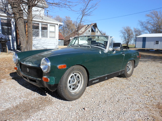
1975 MG Midget - 1500cc; 4 speed. 1640lbs. with the cast iron engine and trans, no bumpers. Those rubber bumpers are almost 150lbs by themselves.
For those of you that don't know what kind of an idiot I am, I will give a brief explanation. I bought the above green hair removal tool to get around with until I could get my 79 SA back up. It seemed to only need a few things and I could either do a swap on it later, or fix it and make a little bit of money by selling it. Instead I found one of the only cars less reliable and a bigger PITA than an old rotary car.
I tried to take the well meaning advice and keep it mostly original and just get it running, As I said, I'm an idiot.
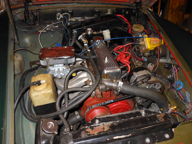
Every time I fixed one thing something else was broken or screwed up. Most of the things had been hidden away by the previous owners when they sold it or broke in the process of fixing something else. After about a year of fighting with it non-stop, and putting far too much money in it, (2 engines, 2 transmissions, carb, manifold, ignition, switches, wiring fixes, radiator, lights, etc etc. ad nauseum). I have had enough with the weak kneed, poorly designed and built, crappy 55hp engine and glass transmission (and worse wiring). Time for something better.
I have put quite a bit of work into suspension/interior/exterior so not all the money dumped into it will be wasted.
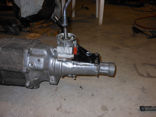
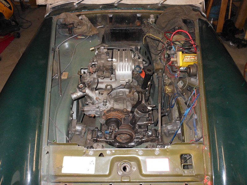
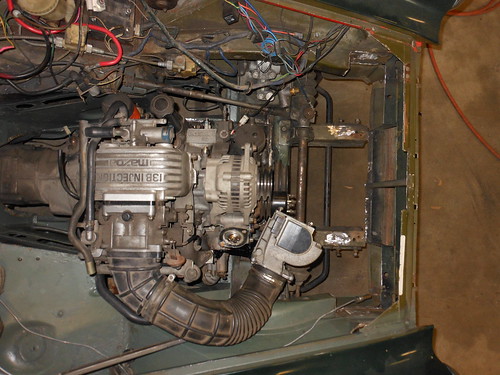
I will be cleaning up the '87 S4 NA 13B and 5 speed that I have and transplant the whole shebang into it. Hopefully I'll be able to retain the fuel injection, but we'll see as I go along. In addition all the wiring will be stripped out of it and either tossed in the trash, or burned in a black Sabbath bonfire to help it on it's way to hell. I will be using the GSL-SE front cover and pan to utilize the front engine mounts. The trickiest part (other than wiring) looks to be building a header, as there isn't a lot of room.
before picture, pretty, but a PITA.
 engine2 by Kevin Frank, on Flickr
**********
Trial fitting. I'll try to document what I ended up doing as thoroughly as I can, in case anyone else ever wants to give this swap a go. I haven't been able to find any build threads on this swap that were very complete. Lots of questions on how others did it, but they didn't share.
Things are even tighter than I thought. I needed some room up front as the front of the rotary is more squared off and wider than the 1500.
1. original front cross member:
 1. original crossmember by Kevin Frank, on Flickr
2. sliced, hammered down, and re-welded:
 2. sliced and welded by Kevin Frank, on Flickr
3. Trimmed and completed front cross member:
 3. completed crossmember by Kevin Frank, on Flickr
Gained 2.25 inches of room up front so I can set the engine down between the frame rails. It looks like I'm going to have to do some clearancing on the rails to get it far enough down and trim the heater box area at the back of the engine as well. (late add: I ended up needing to notch it a bit more for the mounting crossmember bolts)
***********
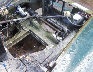
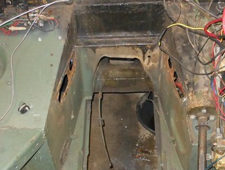
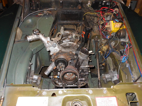
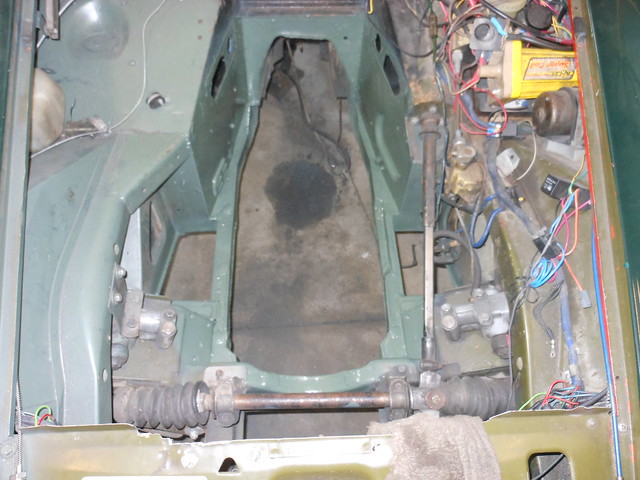
and more trial fitting, it has become apparent that the engine will not go in there without removing the shelf for the heater box and the ducting underneath it (The back of the engine block hits the ducting). I went ahead and took the battery tray out as well. This provides a lot of room to the rear. You could put a straight six in there with this part out. In fact one person did put a Jaguar DOHC six in one. It should also make taking the engine and transmission in and out a WHOLE lot easier.
original heater/battery tray:
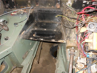 heater box and battery tray - original by Kevin Frank, on Flickr
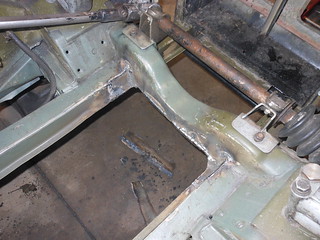
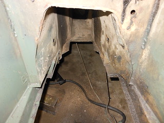
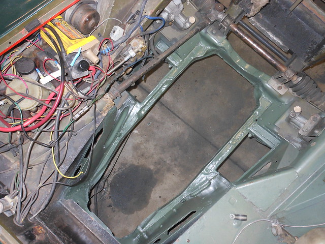
heater/battery tray removed:
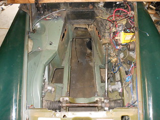 heater box and battery tray - removed by Kevin Frank, on Flickr
Once I have the engine where it needs to be I'll look at rebuilding a spot for the heater. I can do without A/C if I have to, but a heater is important, even if it's only to defog the windshield. The battery will be relocated elsewhere.
Getting that shelf out wasn't easy. I had to drill out a bunch of spot welds, make cuts with the plasma cutter, and do the fine cutting with a cut-off wheel so that I didn't damage something I needed.
So there's your answer to why I haven't gotten anything done on the SA Josh.
I'm building this to work and drive reliably, especially after the amount of frustration I've endured with this car already.
I was hoping to be further along before sharing this on here, but things are slowing down as I run out of funds and a few people wanted to see the build. It's going to come as a big lump until I get caught up.
This is the reason I haven't been able to get more done on my 79 RX7.
lowered by Kevin Frank, on Flickr1975 MG Midget - 1500cc; 4 speed. 1640lbs. with the cast iron engine and trans, no bumpers. Those rubber bumpers are almost 150lbs by themselves.
For those of you that don't know what kind of an idiot I am, I will give a brief explanation. I bought the above green hair removal tool to get around with until I could get my 79 SA back up. It seemed to only need a few things and I could either do a swap on it later, or fix it and make a little bit of money by selling it. Instead I found one of the only cars less reliable and a bigger PITA than an old rotary car.
I tried to take the well meaning advice and keep it mostly original and just get it running, As I said, I'm an idiot.
Every time I fixed one thing something else was broken or screwed up. Most of the things had been hidden away by the previous owners when they sold it or broke in the process of fixing something else. After about a year of fighting with it non-stop, and putting far too much money in it, (2 engines, 2 transmissions, carb, manifold, ignition, switches, wiring fixes, radiator, lights, etc etc. ad nauseum). I have had enough with the weak kneed, poorly designed and built, crappy 55hp engine and glass transmission (and worse wiring). Time for something better.
I have put quite a bit of work into suspension/interior/exterior so not all the money dumped into it will be wasted.
I will be cleaning up the '87 S4 NA 13B and 5 speed that I have and transplant the whole shebang into it. Hopefully I'll be able to retain the fuel injection, but we'll see as I go along. In addition all the wiring will be stripped out of it and either tossed in the trash, or burned in a black Sabbath bonfire to help it on it's way to hell. I will be using the GSL-SE front cover and pan to utilize the front engine mounts. The trickiest part (other than wiring) looks to be building a header, as there isn't a lot of room.
before picture, pretty, but a PITA.
engine2 by Kevin Frank, on Flickr**********
Trial fitting. I'll try to document what I ended up doing as thoroughly as I can, in case anyone else ever wants to give this swap a go. I haven't been able to find any build threads on this swap that were very complete. Lots of questions on how others did it, but they didn't share.
Things are even tighter than I thought. I needed some room up front as the front of the rotary is more squared off and wider than the 1500.
1. original front cross member:
1. original crossmember by Kevin Frank, on Flickr2. sliced, hammered down, and re-welded:
2. sliced and welded by Kevin Frank, on Flickr3. Trimmed and completed front cross member:
3. completed crossmember by Kevin Frank, on FlickrGained 2.25 inches of room up front so I can set the engine down between the frame rails. It looks like I'm going to have to do some clearancing on the rails to get it far enough down and trim the heater box area at the back of the engine as well. (late add: I ended up needing to notch it a bit more for the mounting crossmember bolts)
***********
and more trial fitting, it has become apparent that the engine will not go in there without removing the shelf for the heater box and the ducting underneath it (The back of the engine block hits the ducting). I went ahead and took the battery tray out as well. This provides a lot of room to the rear. You could put a straight six in there with this part out. In fact one person did put a Jaguar DOHC six in one. It should also make taking the engine and transmission in and out a WHOLE lot easier.
original heater/battery tray:
heater box and battery tray - original by Kevin Frank, on Flickrheater/battery tray removed:
heater box and battery tray - removed by Kevin Frank, on FlickrOnce I have the engine where it needs to be I'll look at rebuilding a spot for the heater. I can do without A/C if I have to, but a heater is important, even if it's only to defog the windshield. The battery will be relocated elsewhere.
Getting that shelf out wasn't easy. I had to drill out a bunch of spot welds, make cuts with the plasma cutter, and do the fine cutting with a cut-off wheel so that I didn't damage something I needed.
So there's your answer to why I haven't gotten anything done on the SA Josh.
Thread Starter
Joined: Dec 2010
Posts: 645
Likes: 196
From: Stafford, Ks.
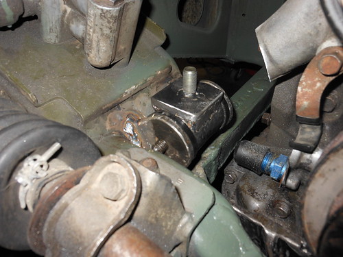
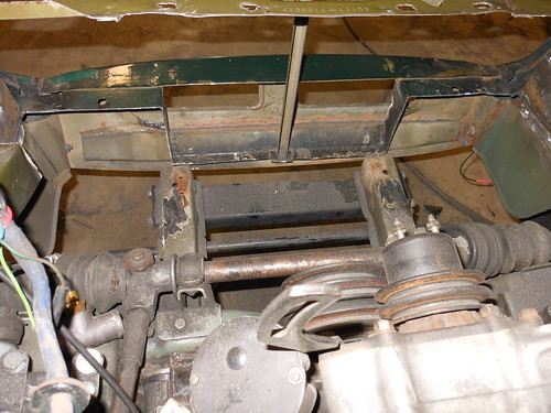
Another necessary modification. The permanent transmission crossmember is too high to slide the transmission into the tunnel. Technically all it really needed was to be notched so the transmission would clear. However a non-removable crossmember makes it a royal PITA if you need to drop the transmission. With the permanent crossmember you have to pull the engine and transmission in one unit to get it out of there. I went ahead and removed the center section of the crossmember and will fabricate some plates for the ends and bolt the modified section back in so that I don't compromise structural integrity.
original:
 trans crossmember - original by Kevin Frank, on Flickr
removed:
 trans crossmember - removed by Kevin Frank, on Flickr
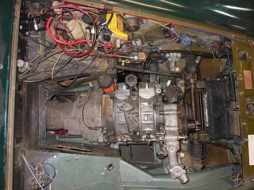
Now to try fitting it back in there. It doesn't appear that the transmission tunnel is going to require much modification to fit the NA transmission. I would imagine that the turbo transmission would be a different story as the NA trans barely fits.
... and engine/trans in place about where it has to sit. I still need to notch the lower rails a little bit to allow the engine to sit a little lower, not as much as I was afraid that I would though. About 1/2 an inch on the passenger side rail should do it.
 engine placement 1 by Kevin Frank, on Flickr
 engine placement 2 by Kevin Frank, on Flickr
 engine placement 3 by Kevin Frank, on Flickr
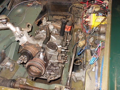
The reason I say that it has to sit here is that it lines my exhaust ports up with the small opening for the exhaust to work it's way under the car. The engine is offset to the right (passenger side) by about an inch to line up with the differential input for a straight line shot with the driveshaft.
 engine placement 4 by Kevin Frank, on Flickr
Needless to say the coolant filler neck is going to need to be modified and shortened.
I will need to cut and box the upper part of the passenger foot well to allow me to use the stock lower intake manifold. Just not enough room without doing it that way. Shouldn't be a problem as nobody has their feet or legs in that spot anyway. It's just wasted space, and space is at a premium with this swap.
The shifter definitely has to be moved forward about 8.5 inches, or more.
Good news is that the end of the transmission tail shaft is only about 3.5 - 4 inches further back than the original 1500 transmission. That shouldn't cause too many problems, I hope.
Here's my solution to a really short shifter. The first picture I had to steal off the internetz as I forgot to take a "before" picture. The FB box in the rear is very similar to the FC box that I have. The shifter box actually sits behind the tail shaft. This is a no go in my application.

So I moved the box forward 9 inches to put it in the stock MG shifter location.
 short shifter 2 by Kevin Frank, on Flickr
 short shifter 1 by Kevin Frank, on Flickr
I've seen prettier renditions of this, but this is how I did it.
The mount was cut off right next to the box and I used the side cover plate to attach a mount using the original rear bolts, one side bolt, and the locator pins. The shaft for the shifter was cut 9 inches and the roll pin hole re-drilled. (I had a machine shop do this for me as I always get the hole off center when I try to drill a round rod). The shaft is not hardened toward the rear so drilling it wasn't a problem. I also had to do a little "massaging" with a grinder on the tail shaft housing. This was necessary to get the box to sit all the way forward against the opening that the shifter shaft exits the case.
It works, but it seems a little stiff right now. Could be that the shaft is binding a little bit which should work it ways out as it gets used or it may be that the RTV I used between the box and the case is pushed up against the shaft.
It does go in and out of all the gears just fine, so I'll give it a try as is.
Right now I'm working on notching the lower frame rails to give me enough room to drop the engine a little lower in the frame.
After about five days of work I finally have the frame modifications finished to make the engine fit in there the way I want it to. It took a while as the mods were more extensive than I thought they would be at first.
You can see the original frame in the original crossmember picture above. (as usual I forgot to take a before picture)
modified:
 Frame mods 1 by Kevin Frank, on Flickr
 frame mods 2 by Kevin Frank, on Flickr
The rotary is a lot wider at the bottom and made it necessary to widen the rails to set it down low. All the other threads I've seen on this set the engine above the frame rails, with attendant problems of the oil pan rails occasionally hitting. Not to mention what it does to the center of gravity.
I welded in two 1/2 thick plates to the outside of each rail between the body tub and the suspension points. Excessive, but it covered the existing flange on the bottom of the rail perfectly. I then trimmed one inch from the inside of each rail and welded 1/8th inch plate to close off the inside. I had to notch the driver's side rail another inch or so for the oil cooler line and the oil bypass sticking out the side of the bottom middle iron. This ended up being the entire width of the rail except for the outer layer. The front crossmember had to be further trimmed to give me enough room to push the engine a little further forward. After taking part of it off I closed it in with more 1/8th inch plate. I then welded in 8 studs and crush tubes along the sides and front for a skid plate/ frame stiffener. It will bolt underneath to tie the entire front suspension together. It will be considerably stronger and stiffer than the original.
Most people don't go this far for the swap, but I'm kind of **** about chassis stiffness and a low center of gravity.
original:
trans crossmember - original by Kevin Frank, on Flickrremoved:
trans crossmember - removed by Kevin Frank, on FlickrNow to try fitting it back in there. It doesn't appear that the transmission tunnel is going to require much modification to fit the NA transmission. I would imagine that the turbo transmission would be a different story as the NA trans barely fits.
... and engine/trans in place about where it has to sit. I still need to notch the lower rails a little bit to allow the engine to sit a little lower, not as much as I was afraid that I would though. About 1/2 an inch on the passenger side rail should do it.
engine placement 1 by Kevin Frank, on Flickrengine placement 2 by Kevin Frank, on Flickrengine placement 3 by Kevin Frank, on FlickrThe reason I say that it has to sit here is that it lines my exhaust ports up with the small opening for the exhaust to work it's way under the car. The engine is offset to the right (passenger side) by about an inch to line up with the differential input for a straight line shot with the driveshaft.
engine placement 4 by Kevin Frank, on FlickrNeedless to say the coolant filler neck is going to need to be modified and shortened.
I will need to cut and box the upper part of the passenger foot well to allow me to use the stock lower intake manifold. Just not enough room without doing it that way. Shouldn't be a problem as nobody has their feet or legs in that spot anyway. It's just wasted space, and space is at a premium with this swap.
The shifter definitely has to be moved forward about 8.5 inches, or more.
Good news is that the end of the transmission tail shaft is only about 3.5 - 4 inches further back than the original 1500 transmission. That shouldn't cause too many problems, I hope.
Here's my solution to a really short shifter. The first picture I had to steal off the internetz as I forgot to take a "before" picture. The FB box in the rear is very similar to the FC box that I have. The shifter box actually sits behind the tail shaft. This is a no go in my application.
So I moved the box forward 9 inches to put it in the stock MG shifter location.
short shifter 2 by Kevin Frank, on Flickrshort shifter 1 by Kevin Frank, on FlickrI've seen prettier renditions of this, but this is how I did it.
The mount was cut off right next to the box and I used the side cover plate to attach a mount using the original rear bolts, one side bolt, and the locator pins. The shaft for the shifter was cut 9 inches and the roll pin hole re-drilled. (I had a machine shop do this for me as I always get the hole off center when I try to drill a round rod). The shaft is not hardened toward the rear so drilling it wasn't a problem. I also had to do a little "massaging" with a grinder on the tail shaft housing. This was necessary to get the box to sit all the way forward against the opening that the shifter shaft exits the case.
It works, but it seems a little stiff right now. Could be that the shaft is binding a little bit which should work it ways out as it gets used or it may be that the RTV I used between the box and the case is pushed up against the shaft.
It does go in and out of all the gears just fine, so I'll give it a try as is.
Right now I'm working on notching the lower frame rails to give me enough room to drop the engine a little lower in the frame.
After about five days of work I finally have the frame modifications finished to make the engine fit in there the way I want it to. It took a while as the mods were more extensive than I thought they would be at first.
You can see the original frame in the original crossmember picture above. (as usual I forgot to take a before picture)
modified:
Frame mods 1 by Kevin Frank, on Flickr frame mods 2 by Kevin Frank, on FlickrThe rotary is a lot wider at the bottom and made it necessary to widen the rails to set it down low. All the other threads I've seen on this set the engine above the frame rails, with attendant problems of the oil pan rails occasionally hitting. Not to mention what it does to the center of gravity.
I welded in two 1/2 thick plates to the outside of each rail between the body tub and the suspension points. Excessive, but it covered the existing flange on the bottom of the rail perfectly. I then trimmed one inch from the inside of each rail and welded 1/8th inch plate to close off the inside. I had to notch the driver's side rail another inch or so for the oil cooler line and the oil bypass sticking out the side of the bottom middle iron. This ended up being the entire width of the rail except for the outer layer. The front crossmember had to be further trimmed to give me enough room to push the engine a little further forward. After taking part of it off I closed it in with more 1/8th inch plate. I then welded in 8 studs and crush tubes along the sides and front for a skid plate/ frame stiffener. It will bolt underneath to tie the entire front suspension together. It will be considerably stronger and stiffer than the original.
Most people don't go this far for the swap, but I'm kind of **** about chassis stiffness and a low center of gravity.
Thread Starter
Joined: Dec 2010
Posts: 645
Likes: 196
From: Stafford, Ks.
The fruits of my weekend.
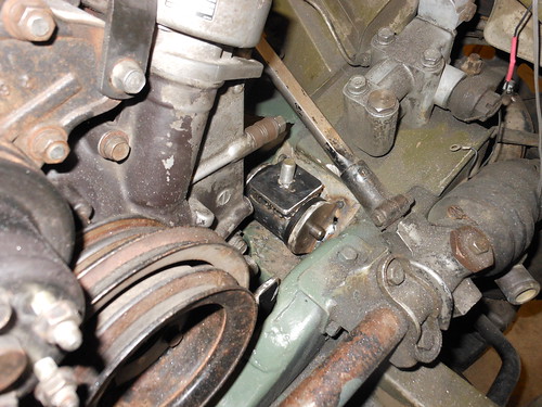
After much trial fitting and head scratching, by Jove! I think I've got it. Engine mounts that is. There wasn't enough room to use the FB or FC stock pads so I improvised with polyurethane captured mounts originally intended for use in rear suspension lower swing arms.
 engine mounts 3 by Kevin Frank, on Flickr
 engine mounts 2 by Kevin Frank, on Flickr
I will extend the front mounting plate over to each and bolt it to the top of each polyurethane mount. There's not a lot of give in this setup so engine placement is going to have to be pretty exact as far as engine angle vs. pinion angle before I weld it up. I used the bolt on approach because if I had simply welded the front plate to the mounts interference from the tabs would have made it nearly impossible to pull the engine without removing the front plate from the engine.
Engine support bar done and the engine is mounted. Lots of fiddling to get bracing in there without interference. As you can see, not a lot of room to work with. This was as low and right as I dared to go. I plan to modify the oil pan/pickup to make the sump shallower and longer. I have full access to the bottom of the pan, but it does hang pretty low with the engine this far down.
 engine crossbar 2 by Kevin Frank, on Flickr
 engine crossbar 1 by Kevin Frank, on Flickr
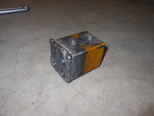
Working on transmission mount.
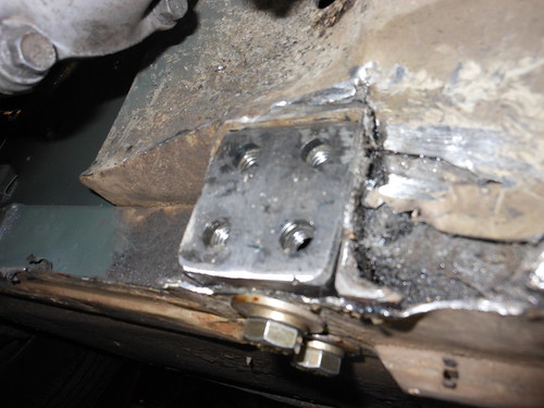
I cut out the original fixed transmission crossmember as it makes getting the engine in and out a royal pain. The problem with cutting it out is that there is nothing to bolt a replacement to. The crossmember is only boxed light sheet metal and is insufficient for bolting a heavier gauge center section to. My solution was to use 2 3/8ths outside square tubing, which slid into the stubs nice and snug. Finding that size tubing is a bit of a bother, but it works perfectly. I then used 1/2" bolts to fasten it within the frame rails. Capped off the ends with some 3/8ths plate and welded nuts inside for both the facing plate and the frame fasteners.
 trans cross member attachment point 2 by Kevin Frank, on Flickr
 trans cross member attachment point 1 by Kevin Frank, on Flickr
There will be a 2" wide (1/4" plate) strip bolted underneath, as part of the center section, with the rest of the center section bolted both below and to the sides. I planned it like this so that I wouldn't be hanging the mount from something that the bolts were in shear.
more pics when I get that done.
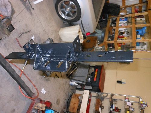
One transmission crossmember; done.
 new transmission crossmember by Kevin Frank, on Flickr
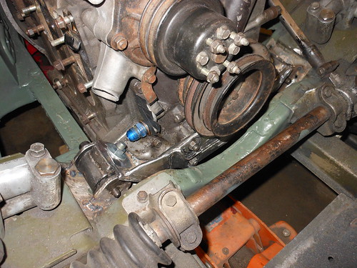
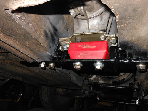
... and pictures of the finished transmission crossmember installed.
 trans crossmember - new - installed by Kevin Frank, on Flickr
I couldn't get the bottom rear side bolts in, there just isn't enough room to get a wrench in the limited space to tighten them. It should be fine with three 7/16ths bolts per side though. Quite often things don't quite work out the way I intended.
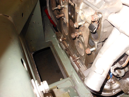
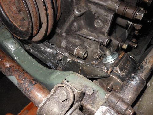
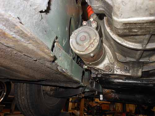
While under the car I took a shot of the frame modification I did for the starter. The starter had me worried, but it fit fine. The only problem was having enough room to get it out without having to pull the engine to do it. I considered that to be what you would call a "bad" thing. So I laid the frame rail back a bit and plan to bend and weld in a piece of 1/8th inch plate to reinforce that spot while leaving me enough room to service the starter when it needs it.
 starter frame relief by Kevin Frank, on Flickr
It fits!!!! :snoopy happy dance:
 13B final position by Kevin Frank, on Flickr
The hood closes with the EFI manifold on the engine. Yaaay!
I have about 1/2" of clearance at the closest point from the top front edge of the manifold to the underside of the hood. Even the filler neck for the coolant fits with plenty of clearance. This is rather astonishing to me. I figured and measured and planned it out to get the engine low enough for it to go in there. I'm actually about two inches lower than I have seen anyone else set the engine in one of these. That two inches was a LOT of work to get though. When you're juggling as many variables as there are in locating an engine in a space this small I've come to expect things not to quite work out right. I's a happy camper right now.
I did have to trim a little more than I expected from the passenger foot well though. I don't think that it will be a problem with where it's at, but if anyone complains I'll just punch it and they'll be so busy hanging on they will forget all about it.
After much trial fitting and head scratching, by Jove! I think I've got it. Engine mounts that is. There wasn't enough room to use the FB or FC stock pads so I improvised with polyurethane captured mounts originally intended for use in rear suspension lower swing arms.
engine mounts 3 by Kevin Frank, on Flickrengine mounts 2 by Kevin Frank, on FlickrI will extend the front mounting plate over to each and bolt it to the top of each polyurethane mount. There's not a lot of give in this setup so engine placement is going to have to be pretty exact as far as engine angle vs. pinion angle before I weld it up. I used the bolt on approach because if I had simply welded the front plate to the mounts interference from the tabs would have made it nearly impossible to pull the engine without removing the front plate from the engine.
Engine support bar done and the engine is mounted. Lots of fiddling to get bracing in there without interference. As you can see, not a lot of room to work with. This was as low and right as I dared to go. I plan to modify the oil pan/pickup to make the sump shallower and longer. I have full access to the bottom of the pan, but it does hang pretty low with the engine this far down.
engine crossbar 2 by Kevin Frank, on Flickrengine crossbar 1 by Kevin Frank, on FlickrWorking on transmission mount.
I cut out the original fixed transmission crossmember as it makes getting the engine in and out a royal pain. The problem with cutting it out is that there is nothing to bolt a replacement to. The crossmember is only boxed light sheet metal and is insufficient for bolting a heavier gauge center section to. My solution was to use 2 3/8ths outside square tubing, which slid into the stubs nice and snug. Finding that size tubing is a bit of a bother, but it works perfectly. I then used 1/2" bolts to fasten it within the frame rails. Capped off the ends with some 3/8ths plate and welded nuts inside for both the facing plate and the frame fasteners.
trans cross member attachment point 2 by Kevin Frank, on Flickrtrans cross member attachment point 1 by Kevin Frank, on FlickrThere will be a 2" wide (1/4" plate) strip bolted underneath, as part of the center section, with the rest of the center section bolted both below and to the sides. I planned it like this so that I wouldn't be hanging the mount from something that the bolts were in shear.
more pics when I get that done.
One transmission crossmember; done.
new transmission crossmember by Kevin Frank, on Flickr... and pictures of the finished transmission crossmember installed.
trans crossmember - new - installed by Kevin Frank, on FlickrI couldn't get the bottom rear side bolts in, there just isn't enough room to get a wrench in the limited space to tighten them. It should be fine with three 7/16ths bolts per side though. Quite often things don't quite work out the way I intended.
While under the car I took a shot of the frame modification I did for the starter. The starter had me worried, but it fit fine. The only problem was having enough room to get it out without having to pull the engine to do it. I considered that to be what you would call a "bad" thing. So I laid the frame rail back a bit and plan to bend and weld in a piece of 1/8th inch plate to reinforce that spot while leaving me enough room to service the starter when it needs it.
starter frame relief by Kevin Frank, on FlickrIt fits!!!! :snoopy happy dance:
13B final position by Kevin Frank, on FlickrThe hood closes with the EFI manifold on the engine. Yaaay!
I have about 1/2" of clearance at the closest point from the top front edge of the manifold to the underside of the hood. Even the filler neck for the coolant fits with plenty of clearance. This is rather astonishing to me. I figured and measured and planned it out to get the engine low enough for it to go in there. I'm actually about two inches lower than I have seen anyone else set the engine in one of these. That two inches was a LOT of work to get though. When you're juggling as many variables as there are in locating an engine in a space this small I've come to expect things not to quite work out right. I's a happy camper right now.
I did have to trim a little more than I expected from the passenger foot well though. I don't think that it will be a problem with where it's at, but if anyone complains I'll just punch it and they'll be so busy hanging on they will forget all about it.
Thread Starter
Joined: Dec 2010
Posts: 645
Likes: 196
From: Stafford, Ks.
So I spent an entire day doing this. Just one little piece of tube, that's all. Right!
 13B header 1 by
 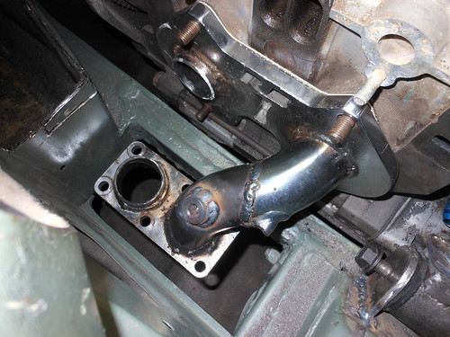 13B header 2 by Kevin Frank, on Flickr
well besides the tube, I did get the O2 sensor bung welded in on that day, so that's two things I guess.
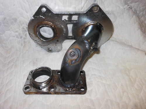
I am modifying the Racing Beat 6 port header, that I already had, to fit in the midget. It will have to be a two piece design if I am to have any hope of ever getting it in and out of the car. This is the upper portion mating to a road race outlet flange. It will be mated to a lower section using the same type of flange and making an immediate 90 straight back. Needless to say there was lots of fiddling to get it just right so that everything would go where it needs to. Now that I have a better idea of what I will need, I ordered some more flanges, bends, and straight tube from Racing Beat to finish part of the exhaust system.
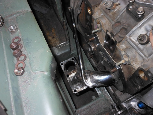
S4 specific Six port actuator tube installed. Has to be at just the right angle and spacing to make it possible to still slide the header out of there.
 13B header six port actuator tube by
 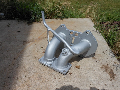 upper exhaust manifold (finished) by Kevin Frank, on Flickr
installed:
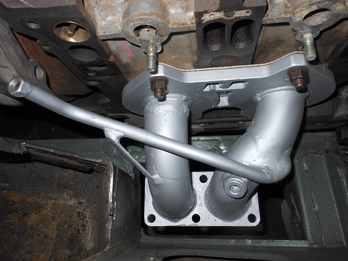 upper exhaust manifold (installed) by Kevin Frank, on Flickr
So, a few days to catch up on.
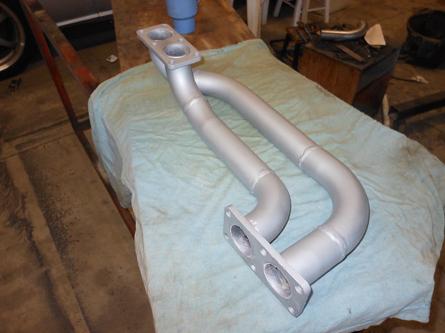
Finished the mid pipe section and got paint on it. I will probably need to make up some heat shields for the pipes. They have to run pretty close to the floor pan as there is very little ground clearance on these cars and nowhere to tuck the pipe up and out of the way. I still have about 1/2" of clearance, but didn't dare tuck it up any higher due to the rotary's high exhaust temperatures.
 mid pipe 1 by Kevin Frank, on Flickr
The end of this will connect to an X pipe section that passes underneath the transmission. It will bolt to the exhaust on either side of the tunnel opening. This will give me a section that I can drop out to remove the transmission, without having to take out the entire exhaust system each time. The downside to this approach is that there are more gasketed joints (and possible leak points) in the system. Once out of the X pipe section, I plan to 90 the dual pipes toward the rear of the car (putting in another flange just before it turns up to go over the axle) and all the way over the axle before I run it into a 3" collector at the back of the axle tunnel. At that point it will go to a 3" Racing Beat pre-silencer, make a 90 into a 3" RB muffler, then make another 90 out the back on the passenger side. The reason for this is more so space considerations than for the long primary. Space is so tight over the axle that the 2" pipe is going to be a tight squeeze, anything bigger would be sure to hit on suspension compression. That's the plan anyway.
 mid pipe 2 by Kevin Frank, on Flickr
and a shot of where it connects to the upper section of the header/manifold.
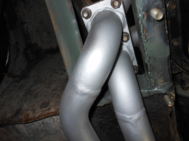 mid pipe 3 by Kevin Frank, on Flickr
Probably not going to get a lot else done on the exhaust for a while. Out of money, ... again.
13B header 1 by 13B header 2 by Kevin Frank, on Flickrwell besides the tube, I did get the O2 sensor bung welded in on that day, so that's two things I guess.
I am modifying the Racing Beat 6 port header, that I already had, to fit in the midget. It will have to be a two piece design if I am to have any hope of ever getting it in and out of the car. This is the upper portion mating to a road race outlet flange. It will be mated to a lower section using the same type of flange and making an immediate 90 straight back. Needless to say there was lots of fiddling to get it just right so that everything would go where it needs to. Now that I have a better idea of what I will need, I ordered some more flanges, bends, and straight tube from Racing Beat to finish part of the exhaust system.
S4 specific Six port actuator tube installed. Has to be at just the right angle and spacing to make it possible to still slide the header out of there.
13B header six port actuator tube by upper exhaust manifold (finished) by Kevin Frank, on Flickrinstalled:
upper exhaust manifold (installed) by Kevin Frank, on FlickrSo, a few days to catch up on.
Finished the mid pipe section and got paint on it. I will probably need to make up some heat shields for the pipes. They have to run pretty close to the floor pan as there is very little ground clearance on these cars and nowhere to tuck the pipe up and out of the way. I still have about 1/2" of clearance, but didn't dare tuck it up any higher due to the rotary's high exhaust temperatures.
mid pipe 1 by Kevin Frank, on FlickrThe end of this will connect to an X pipe section that passes underneath the transmission. It will bolt to the exhaust on either side of the tunnel opening. This will give me a section that I can drop out to remove the transmission, without having to take out the entire exhaust system each time. The downside to this approach is that there are more gasketed joints (and possible leak points) in the system. Once out of the X pipe section, I plan to 90 the dual pipes toward the rear of the car (putting in another flange just before it turns up to go over the axle) and all the way over the axle before I run it into a 3" collector at the back of the axle tunnel. At that point it will go to a 3" Racing Beat pre-silencer, make a 90 into a 3" RB muffler, then make another 90 out the back on the passenger side. The reason for this is more so space considerations than for the long primary. Space is so tight over the axle that the 2" pipe is going to be a tight squeeze, anything bigger would be sure to hit on suspension compression. That's the plan anyway.
mid pipe 2 by Kevin Frank, on Flickrand a shot of where it connects to the upper section of the header/manifold.
mid pipe 3 by Kevin Frank, on FlickrProbably not going to get a lot else done on the exhaust for a while. Out of money, ... again.
Thread Starter
Joined: Dec 2010
Posts: 645
Likes: 196
From: Stafford, Ks.
While waiting for more funds I'll work on other stuffs. Time to address the other big bug-a-boo with this swap. Cooling.
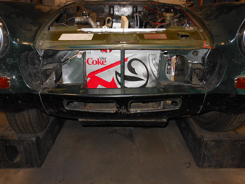
Since the rotary requires far more cooling than the original piston engine, and frontal area is so limited, I had to plan out some rather strange stuff. The FC radiator is a single pass unit with 374 square inches of frontal area. The oil cooler carries about 30% of the engine cooling and is about 91.5 square inches of frontal area. The original MG radiator has only 140 square inches of frontal area and no oil cooler standard. Obviously we have a problem Houston. The tiny opening was going to need some rethinking to get a lot bigger radiator in there, not to mention what to do about an oil cooler.
Here's a picture of the original opening after I had made some cuts to open it up a little. The Diet Coke box was supposed to only be background so you could see the opening better. Didn't work so well, but you get what you pay for.
 radiator opening 1 by Kevin Frank, on Flickr
I'm going to open it up to the full width of the car. Removing the front stubs of the upper frame rails so I can fit the side tanks all the way up against the sides and maximize my radiator size with a 14" x 28" double pass radiator. I'm still down a little on frontal area from the FC radiator at only about 336 square inches, but I hope the extra efficiency of the double pass unit will make up the difference. Unfortunately it is going to have to be custom made so it's going to be expensive.
The oil cooler I plan to use is an 11"x11" square stacked plate cooler that I will set underneath the radiator and between the frame rails. It is actually about 30 square inches larger in surface are than the original. However because I plan to mount it flat, (not much choice as there is just no room anywhere else), it will have less than great air flow. I plan to run a shallow scoop under the car to gather air for the oil cooler and run the fan shroud over the cooler along with the fan so that it draws air through both.
A picture of the radiator opening, partially opened.
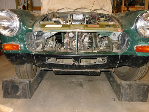 radiator opening 2 by Kevin Frank, on Flickr
front radiator opening fully trimmed with the frame rails trimmed back to allow access for an over size radiator.
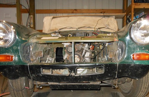 radiator opening by Kevin Frank, on Flickr
... and the back side.
 radiator opening (back) by Kevin Frank, on Flickr
This is the maximum opening that I could manage without altering the external bodywork.
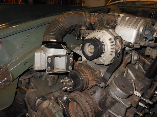
... and to continue the saga figuring out my air intake (Have to do that to make sure I don't have interference problems with the radiator). I made a somewhat complicated bracket and mounted my AFM up at the front of the engine. I wanted to use the stock 13B intake piping and the radiator would be in the way to mount it in the same place as the RX7. I plan to run the intake across the front of the engine (up high and behind the radiator shroud) and plumb in a cold air intake and filter box on the driver's side. I'm trying to figure out a way to tuck the filter box high in the wheel well, directly behind the headlight, as this is the only reasonably clear unused space up front. Still puzzling over that one.
 AFM bracket by Kevin Frank, on Flickr
 AFM placement 1 by Kevin Frank, on Flickr
 AFM placement 2 by Kevin Frank, on Flickr
 AFM placement 3 by Kevin Frank, on Flickr
There was a little interference from the hood prop tab, but whacked off the tab with the cut off wheel and now fits fine.
In order to get accurate measurements for the intake system I need to get a few other things situated. I had to make a new battery box and mounts from scratch to relocate it. It was originally mounted up by the windshield cowl, but that area is no longer there..
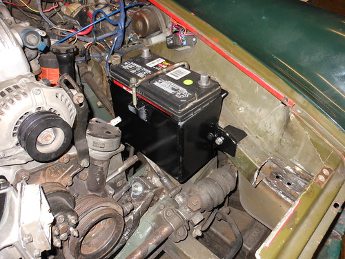 battery box by Kevin Frank, on Flickr
Now on to mounting my coils.
Since the rotary requires far more cooling than the original piston engine, and frontal area is so limited, I had to plan out some rather strange stuff. The FC radiator is a single pass unit with 374 square inches of frontal area. The oil cooler carries about 30% of the engine cooling and is about 91.5 square inches of frontal area. The original MG radiator has only 140 square inches of frontal area and no oil cooler standard. Obviously we have a problem Houston. The tiny opening was going to need some rethinking to get a lot bigger radiator in there, not to mention what to do about an oil cooler.
Here's a picture of the original opening after I had made some cuts to open it up a little. The Diet Coke box was supposed to only be background so you could see the opening better. Didn't work so well, but you get what you pay for.
radiator opening 1 by Kevin Frank, on FlickrI'm going to open it up to the full width of the car. Removing the front stubs of the upper frame rails so I can fit the side tanks all the way up against the sides and maximize my radiator size with a 14" x 28" double pass radiator. I'm still down a little on frontal area from the FC radiator at only about 336 square inches, but I hope the extra efficiency of the double pass unit will make up the difference. Unfortunately it is going to have to be custom made so it's going to be expensive.
The oil cooler I plan to use is an 11"x11" square stacked plate cooler that I will set underneath the radiator and between the frame rails. It is actually about 30 square inches larger in surface are than the original. However because I plan to mount it flat, (not much choice as there is just no room anywhere else), it will have less than great air flow. I plan to run a shallow scoop under the car to gather air for the oil cooler and run the fan shroud over the cooler along with the fan so that it draws air through both.
A picture of the radiator opening, partially opened.
radiator opening 2 by Kevin Frank, on Flickrfront radiator opening fully trimmed with the frame rails trimmed back to allow access for an over size radiator.
radiator opening by Kevin Frank, on Flickr... and the back side.
radiator opening (back) by Kevin Frank, on FlickrThis is the maximum opening that I could manage without altering the external bodywork.
... and to continue the saga figuring out my air intake (Have to do that to make sure I don't have interference problems with the radiator). I made a somewhat complicated bracket and mounted my AFM up at the front of the engine. I wanted to use the stock 13B intake piping and the radiator would be in the way to mount it in the same place as the RX7. I plan to run the intake across the front of the engine (up high and behind the radiator shroud) and plumb in a cold air intake and filter box on the driver's side. I'm trying to figure out a way to tuck the filter box high in the wheel well, directly behind the headlight, as this is the only reasonably clear unused space up front. Still puzzling over that one.
AFM bracket by Kevin Frank, on FlickrAFM placement 1 by Kevin Frank, on FlickrAFM placement 2 by Kevin Frank, on FlickrAFM placement 3 by Kevin Frank, on FlickrThere was a little interference from the hood prop tab, but whacked off the tab with the cut off wheel and now fits fine.
In order to get accurate measurements for the intake system I need to get a few other things situated. I had to make a new battery box and mounts from scratch to relocate it. It was originally mounted up by the windshield cowl, but that area is no longer there..
battery box by Kevin Frank, on FlickrNow on to mounting my coils.
Thread Starter
Joined: Dec 2010
Posts: 645
Likes: 196
From: Stafford, Ks.
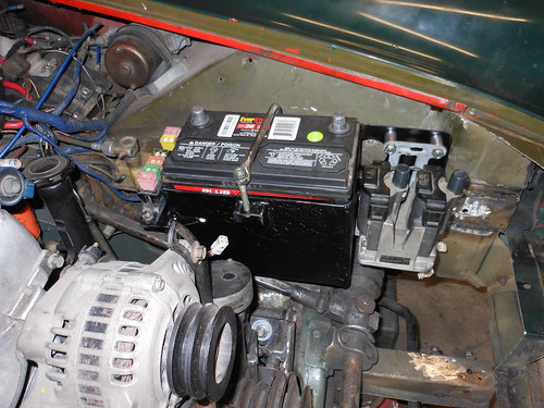
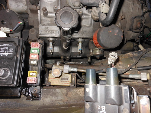
Trailing coil and main FC fuse panel mounted.
 trailing coil by Kevin Frank, on Flickr
I screwed up on the paint. I was going to do some touch up on the box and mounts. Bought the wrong paint and it's now lifting. I'll need to sandblast it all off and start over on the paint when I get to it.
trailing coil by Kevin Frank, on FlickrI screwed up on the paint. I was going to do some touch up on the box and mounts. Bought the wrong paint and it's now lifting. I'll need to sandblast it all off and start over on the paint when I get to it.
Thread Starter
Joined: Dec 2010
Posts: 645
Likes: 196
From: Stafford, Ks.
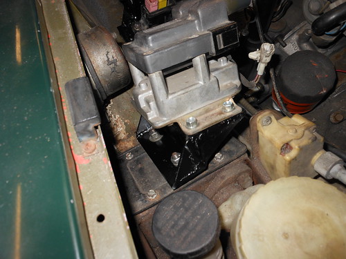
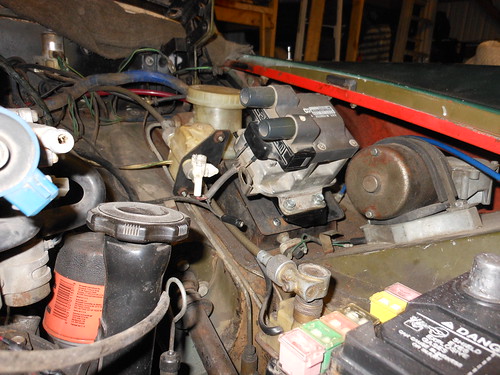
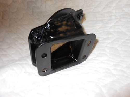
... and leading coil is mounted.
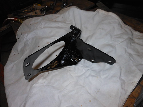
built a bracket to bolt where the original coil went ...
 leading coil bracket by Kevin Frank, on Flickr
mounted the coil ...
 leading coil mounted by Kevin Frank, on Flickr
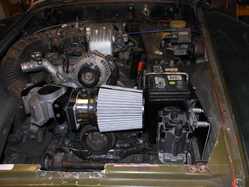
and a picture of the whole ensemble.
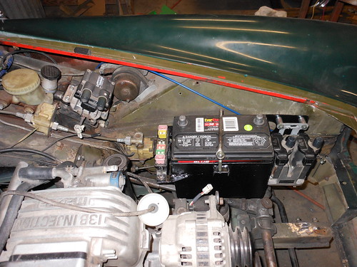 coils and battery by Kevin Frank, on Flickr
built a bracket to bolt where the original coil went ...
leading coil bracket by Kevin Frank, on Flickrmounted the coil ...
leading coil mounted by Kevin Frank, on Flickrand a picture of the whole ensemble.
coils and battery by Kevin Frank, on Flickr
Trending Topics
Thread Starter
Joined: Dec 2010
Posts: 645
Likes: 196
From: Stafford, Ks.
a picture of the spark plug access, since I was asked about it. There's room, maybe not gobs of it, but better than an RX8.
 spark plug access by Kevin Frank, on Flickr
spark plug access by Kevin Frank, on Flickr
Wow, I think I might like your header better than mine. I'm sure it will make install/removal easier than mine.
Wow, you really chopped out a lot of sheet metal. It should make your life easier than mine has been.
So EFI, then? I installed an S4 NA into the red '84 GSL but in the end it turns out I like the hogged out Nikki I installed in the brown GSL-SE a lot better. So I decided on a similar hogged out setup in my MG along with a nice long primary exhaust.
Have you seen my rotarded MG thread? It's around here somewhere.
I will say this about your setup. I like all the little black painted steel brackets everywhere.
Thread Starter
Joined: Dec 2010
Posts: 645
Likes: 196
From: Stafford, Ks.
Wow, I think I might like your header better than mine. I'm sure it will make install/removal easier than mine.
Wow, you really chopped out a lot of sheet metal. It should make your life easier than mine has been.
So EFI, then? I installed an S4 NA into the red '84 GSL but in the end it turns out I like the hogged out Nikki I installed in the brown GSL-SE a lot better. So I decided on a similar hogged out setup in my MG along with a nice long primary exhaust.
Have you seen my rotarded MG thread? It's around here somewhere.
I will say this about your setup. I like all the little black painted steel brackets everywhere.
Wow, you really chopped out a lot of sheet metal. It should make your life easier than mine has been.
So EFI, then? I installed an S4 NA into the red '84 GSL but in the end it turns out I like the hogged out Nikki I installed in the brown GSL-SE a lot better. So I decided on a similar hogged out setup in my MG along with a nice long primary exhaust.
Have you seen my rotarded MG thread? It's around here somewhere.
I will say this about your setup. I like all the little black painted steel brackets everywhere.
I had to remove a lot of sheetmetal to open up the space for the stock lower intake manifold and to maximize cooling. The original MG radiator and opening was pathetic. I was having cooling problems with the 1500 so I'm going to do everything within my power to eliminate that particular problem with the 13B.
A lot of my planning and figuring time went into keeping the EFI. I had to set the engine lower than they did in yours to make the upper manifold fit under the hood. It does, but just barely. I'll be running a header primary pretty much over the back axle. I'm doing this more so out of space considerations than for any torque benefits. If I get those it will be great too of course. With the pipes running under the floorpan as they do, there is just no room for a large diameter pipe, unless I went with oval pipe, or kept the 2" diameter twin pipe, there was no way to get sufficient exhaust flow out the back. Unfortunately I couldn't find anyone that had heavy gauge oval pipe like a rotary requires, so keeping the twin pipe all the way under the car is what I decided to do. I am planning to run an X pipe under the transmission tunnel to help with scavenging and reduce some of the exhaust pulse spikes. I'm hoping it helps quiet things down a touch more as I would like to keep my eardrums intact. A rotary with an exhaust system this short is likely to be a bit louder than I want.
The little steel brackets are the poor man's way of securing stuff correctly without breaking the bank.
I'm trying to keep the costs down on this build as much as I can, but there are going to be plenty of things that are going to get spendy regardless of what I think. 
I just hope to finally have a Midget that actually runs without being broke every other time it leaves the shop and entertaining to boot.

Thread Starter
Joined: Dec 2010
Posts: 645
Likes: 196
From: Stafford, Ks.
Thanks, a long way to go yet. The weight distribution on these cars is already biased toward the rear of the car. With the lighter engine this will only make this more pronounced. I would like to keep it as near 50/50 as possible so I am trying to keep as much weight forward as possible. Which is why I did so much work to push the engine as far forward as I reasonably could.
Thread Starter
Joined: Dec 2010
Posts: 645
Likes: 196
From: Stafford, Ks.
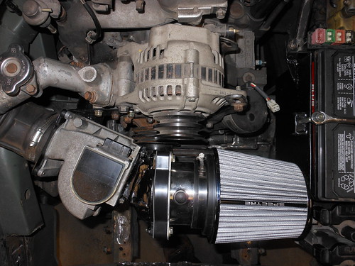
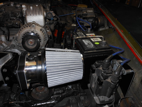
I got the intake side pretty much done while I'm waiting for my Racing Beat muffler to get here. There was no way to route the intake tract, and no room for the filter, where I was thinking to put it. This was the best I could come up with for now. I may try to build a canister surround and do a cold air pick up for it later. I need to see where everything else [i.e. radiator and shroud/oil cooler(s), etc.] will fit first.
I had to build an adapter to go from the AFM to the standard flange for a 4" ID filter that is 6 inches in diameter and about 6.5 inches in length.
 air filter bracket 2 by Kevin Frank, on Flickr
... and pictures of the filter installed.
 air filter 1 by Kevin Frank, on Flickr
 air filter 2 by Kevin Frank, on Flickr
The flanges are a very tight fit. They just barely clear the water pump pulley. Packaging is very tight in one of these cars.
The muffler is supposed to be here Tuesday. I need to get the placement done on that before I can make any further plans about the rest of the exhaust. It's also going to impact the size and placement of my decision on a fuel tank. Still very much up in the air about what to do about that for now.
I had to build an adapter to go from the AFM to the standard flange for a 4" ID filter that is 6 inches in diameter and about 6.5 inches in length.
air filter bracket 2 by Kevin Frank, on Flickr... and pictures of the filter installed.
air filter 1 by Kevin Frank, on Flickrair filter 2 by Kevin Frank, on FlickrThe flanges are a very tight fit. They just barely clear the water pump pulley. Packaging is very tight in one of these cars.
The muffler is supposed to be here Tuesday. I need to get the placement done on that before I can make any further plans about the rest of the exhaust. It's also going to impact the size and placement of my decision on a fuel tank. Still very much up in the air about what to do about that for now.
Thread Starter
Joined: Dec 2010
Posts: 645
Likes: 196
From: Stafford, Ks.
Looking around to see what else I can accomplish while waiting on parts.
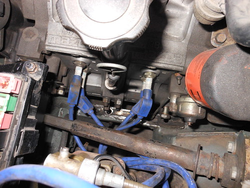
I thought it would be appropriate to post these pictures for anyone planning out a similar swap. Fitted my existing spark plug wires to check for fit. I believe these were stock size, but I couldn't swear to it as they came (almost new) on the engine when I bought it. I have plenty of extra for looms so I think that any wires made for the FC RX7 should work.
 spark plug wires 1 by Kevin Frank, on Flickr
 spark plug wires 2 by Kevin Frank, on Flickr
I thought it would be appropriate to post these pictures for anyone planning out a similar swap. Fitted my existing spark plug wires to check for fit. I believe these were stock size, but I couldn't swear to it as they came (almost new) on the engine when I bought it. I have plenty of extra for looms so I think that any wires made for the FC RX7 should work.
spark plug wires 1 by Kevin Frank, on Flickrspark plug wires 2 by Kevin Frank, on Flickr

Thread Starter
Joined: Dec 2010
Posts: 645
Likes: 196
From: Stafford, Ks.
Thread Starter
Joined: Dec 2010
Posts: 645
Likes: 196
From: Stafford, Ks.
While I've been waiting for my muffler to get here I have been piddling with a few things. Did some more trimming for the radiator and figured out which one I'm going to try. The VW Scirocco radiator would have fit well in the front opening, but it's a little smaller than I would like. It probably would have been fine, but I get really nervous about over heating a rotary. I looked it over again and checked out what a few others have done. I believe I can fit an off the shelf 15.5 x 31 radiator in there. This will put me just over 400 square inches and is meant to cool an LS V8, so it should do the trick handily (provided I can make it fit of course). It will require a few modifications to the radiator and a lot more modification of the front radiator area, but should be quite a bit cheaper than a custom built radiator.
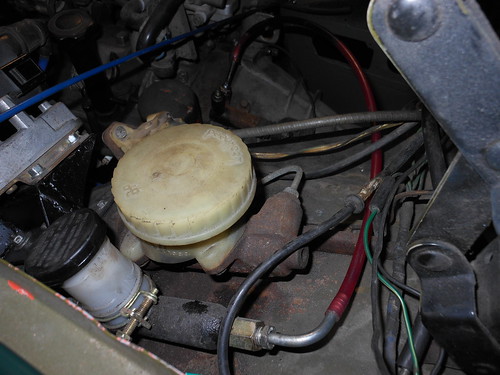
The other thing I did I would have sworn would not work. I modified the clutch slave line attachment using pieces from both the MG and an old slave cylinder I had from a 12A. I cut off most of the hose portion of the 12A line and drilled it out with a 1/4" drill bit. I then removed the slave cylinder fitting from the MG plastic line, straightened it out, and slipped it into the drilled 12A fitting. I then welded the MG line to the 12A fitting because I was concerned that it may leak otherwise. I shortened the plastic clutch line and heated up the new fitting with a Propane torch. I then inserted the barbed end of the steel MG line fitting back into the plastic line. It needed some cleanup inside the line, but when I hooked it to the original MG master cylinder (filled and purged of course), it worked. It seems to be fully disengaging the clutch and no leaks so far. We'll have to see if it works as well as it appears once it's running though.
a picture of the MG clutch master cylinder hooked to the Mazda clutch slave cylinder.
 clutch master by Kevin Frank, on Flickr
and a picture of the Mazda clutch slave with the modified fitting.
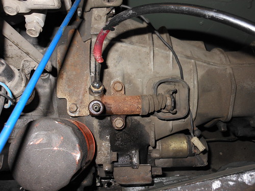 clutch slave by Kevin Frank, on Flickr
It's definitely not pretty, but I was not expecting this to work. I thought it was worth a try while I was waiting for parts is all.
The other thing I did I would have sworn would not work. I modified the clutch slave line attachment using pieces from both the MG and an old slave cylinder I had from a 12A. I cut off most of the hose portion of the 12A line and drilled it out with a 1/4" drill bit. I then removed the slave cylinder fitting from the MG plastic line, straightened it out, and slipped it into the drilled 12A fitting. I then welded the MG line to the 12A fitting because I was concerned that it may leak otherwise. I shortened the plastic clutch line and heated up the new fitting with a Propane torch. I then inserted the barbed end of the steel MG line fitting back into the plastic line. It needed some cleanup inside the line, but when I hooked it to the original MG master cylinder (filled and purged of course), it worked. It seems to be fully disengaging the clutch and no leaks so far. We'll have to see if it works as well as it appears once it's running though.
a picture of the MG clutch master cylinder hooked to the Mazda clutch slave cylinder.
clutch master by Kevin Frank, on Flickrand a picture of the Mazda clutch slave with the modified fitting.
clutch slave by Kevin Frank, on FlickrIt's definitely not pretty, but I was not expecting this to work. I thought it was worth a try while I was waiting for parts is all.
Did you see how I did my master & slave? They're from an FC. I did it based on what RX-Midget said to do. Then I redid the lever position to make the pedal travel a little longer. It went from being too short and stiff to being longer and just about right. I'd have preferred even more travel, but it turned out well enough. About an easy 6 or a 5.5 on my scale.
Pics of the finished product are in my thread.
Pics of the finished product are in my thread.
Thread Starter
Joined: Dec 2010
Posts: 645
Likes: 196
From: Stafford, Ks.
I saw how you did it Jeff. I was messing around and thought what the heck, let's try it and see what happens. I actually have the same pedal travel as the stock MG and pedal effort is about the same as the stock first Gen. Still no leaks and it was quite easy to do. We'll have to see if it works right when I get it going. If not, I'll start digging through my piles of stuff to find my FC parts to do it the way you have it.
I did receive this from UPS today.
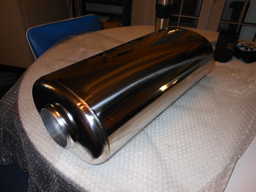 muffler by Kevin Frank, on Flickr
Now I just have to make it fit in a non-existent space.
I did receive this from UPS today.
muffler by Kevin Frank, on FlickrNow I just have to make it fit in a non-existent space.
Thread Starter
Joined: Dec 2010
Posts: 645
Likes: 196
From: Stafford, Ks.
I'm kind of committed at this point.
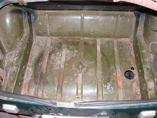 trunk area - before by Kevin Frank, on Flickr
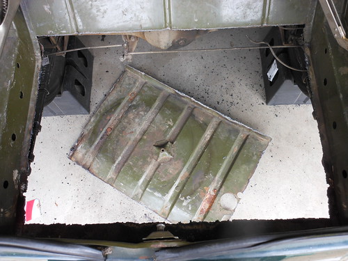 trunk - cut out 2 by Kevin Frank, on Flickr
 trunk - cut out 1 by Kevin Frank, on Flickr
I was cringing a bit when I started making the cuts, but it had to be done to get a decent sized muffler and fuel tank in there.
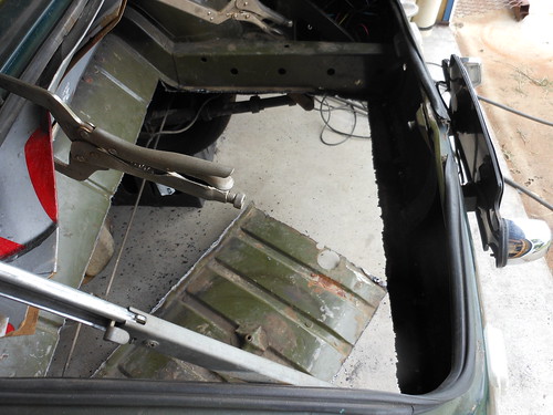
... and the position where the muffler is going to fit.
 muffler position by Kevin Frank, on Flickr
I'm going to lose about 6.5 inches of trunk space due to raising the floor that far. Shouldn't be any worse than when there is a spare tire in there though. It will allow me to fit the muffler, with plenty of air space around it, and to fit a standard 20 gallon fuel cell (24x20x10) if that's what I end up going with. The bottom edge of the muffler and the fuel cell will project below the car by about 2 inches, but I don't think that should be a problem. It's not a 4x4 and departure angle shouldn't be too big of a worry.
trunk area - before by Kevin Frank, on Flickrtrunk - cut out 2 by Kevin Frank, on Flickrtrunk - cut out 1 by Kevin Frank, on FlickrI was cringing a bit when I started making the cuts, but it had to be done to get a decent sized muffler and fuel tank in there.
... and the position where the muffler is going to fit.
muffler position by Kevin Frank, on FlickrI'm going to lose about 6.5 inches of trunk space due to raising the floor that far. Shouldn't be any worse than when there is a spare tire in there though. It will allow me to fit the muffler, with plenty of air space around it, and to fit a standard 20 gallon fuel cell (24x20x10) if that's what I end up going with. The bottom edge of the muffler and the fuel cell will project below the car by about 2 inches, but I don't think that should be a problem. It's not a 4x4 and departure angle shouldn't be too big of a worry.
Thread Starter
Joined: Dec 2010
Posts: 645
Likes: 196
From: Stafford, Ks.
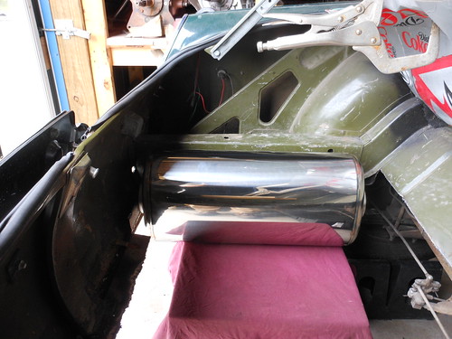
Finalized what I'm going to do about a fuel tank. After removing the floor I was able to reassess the situation before I got too carried away. I was able to fit a stock 87 FC tank in there by the skin on my teeth. This will greatly simplify the fuel system and give me about an extra 10 gallons of fuel so I don't have to be constantly on the hunt for gas stations.
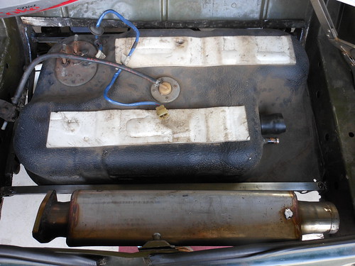 fuel tank 4 (bolted in) by Kevin Frank, on Flickr
Unfortunately the Racing Beat muffler just will not work behind the tank. It is just a hair too wide and would leave me with insufficient air gap between the tank and muffler. I will have to use one of the Spin Tech mufflers that I had. I didn't really want to use one of these as they are a bit loud. I guess that means I'll have to get really creative on the pre-silencer. It's looking more and more like I'm going to need to use thinner wall oval tubing to make this all work.
fuel tank 4 (bolted in) by Kevin Frank, on FlickrUnfortunately the Racing Beat muffler just will not work behind the tank. It is just a hair too wide and would leave me with insufficient air gap between the tank and muffler. I will have to use one of the Spin Tech mufflers that I had. I didn't really want to use one of these as they are a bit loud. I guess that means I'll have to get really creative on the pre-silencer. It's looking more and more like I'm going to need to use thinner wall oval tubing to make this all work.
I figured you wouldn't be able to use the RB muffler.
I have dual 4" presilencers under my floorboards and magnapack behind my stock tank. Doesn't leave a lot of ground clearance but I will have enough muffling and a useable trunk.
I have dual 4" presilencers under my floorboards and magnapack behind my stock tank. Doesn't leave a lot of ground clearance but I will have enough muffling and a useable trunk.
Thread Starter
Joined: Dec 2010
Posts: 645
Likes: 196
From: Stafford, Ks.
As long as I can shoehorn a spare in the trunk I'm all good. It's not as if there was room for much of anything in there anyway.
Thread Starter
Joined: Dec 2010
Posts: 645
Likes: 196
From: Stafford, Ks.
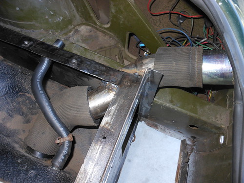
This is what I've been fighting with for the past few days.
 Fuel pass through 1 by Kevin Frank, on Flickr
I had to weld a few different angles together to make a pass through in my fuel tank enclosure for the stock fuel filler. The vent pass through only required a straight piece, so that one was easy. The fuel filler involved a bunch of different angles, so it was a bit more of a pain to do. I'll get paint on the enclosure (some of it will be impossible to get paint on once it is in) and get it welded in position, pictures of that will be forthcoming.
Fuel pass through 1 by Kevin Frank, on FlickrI had to weld a few different angles together to make a pass through in my fuel tank enclosure for the stock fuel filler. The vent pass through only required a straight piece, so that one was easy. The fuel filler involved a bunch of different angles, so it was a bit more of a pain to do. I'll get paint on the enclosure (some of it will be impossible to get paint on once it is in) and get it welded in position, pictures of that will be forthcoming.