
Rotary MX-5 Nordschleife Build Thread

Crapengineering in UK sells custom made tubular subframes  In case you want something lighter and better suited for the 13B.
They are made for the KL V6, but should fit yours better than the stock one. But i guess you are to far along to change that now.
In case you want something lighter and better suited for the 13B.They are made for the KL V6, but should fit yours better than the stock one. But i guess you are to far along to change that now.
Thread Starter
Junior Member

Joined: Jan 2018
Posts: 47
Likes: 12
From: Germany
Kenku, this kind of research is great! All facts considered, I will see what I can do with the space that we have available. Thank you for your continuous support!
This is true, the modified subframe is pretty heavy. I think back in the day when I started there was also noone fabricating tubular subframes in europe. Thanks for the hint, I have been in contact with Ali from Crapengineering already. This surely is something I want to fit for the weight benefits later down the line.
I have another question regarding a full bridge. I was under the impression that full bridges with notched housings work with 2-piece seals, since there are rebuild videos of "RX7 Specialties" and "FullBOOST" that did just that. However there are some old threads on here where people argued that when this is done, the triangle piece will cause problems. The seals I bought are regular Atkins 2-piece seals, I have read that appearently they are engineered slightly differently to allow for a bigger bridge. Not sure how big of a bridge I can build on the triangle-piece side.
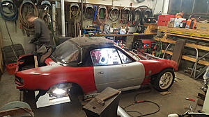
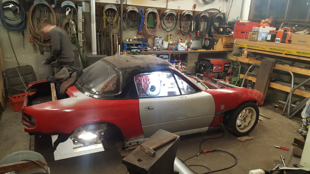
Here is the car in its current condition:
I have another question regarding a full bridge. I was under the impression that full bridges with notched housings work with 2-piece seals, since there are rebuild videos of "RX7 Specialties" and "FullBOOST" that did just that. However there are some old threads on here where people argued that when this is done, the triangle piece will cause problems. The seals I bought are regular Atkins 2-piece seals, I have read that appearently they are engineered slightly differently to allow for a bigger bridge. Not sure how big of a bridge I can build on the triangle-piece side.
Here is the car in its current condition:
Full Member
Joined: Feb 2013
Posts: 116
Likes: 0
From: France
Hi man !
I am the french man, with the green 13b PP miata
Good to see people all around the world taking on the same project !
It will be long and difficult and painful, but it will be all worth it in the end. The miata is a great car to begin with, once you've added a few mods.
But when you put a rotary in it, it becomes a ******* laugh machine !!
One thing you should think about RIGHT NOW is cooling. The NA miata hasn't much of bumper surface for many coolers. So you gotta be creative.
On the track, i could't do 3 laps without having the oil at 140�C because i didn't design it the right way from the beginning (mine is a PP mind you, with 250whp so more heat than a sideport engine).
First, i put the FC oil cooler in front of the radiator, in the bumper mouth : it blocked the airflow completely : oil and water overheated badly. One thing i noticed though, in N/A form, my engine had its water at 120�C a few times, and the water seals hold perfectly. Without a turbo, it is much much more forgiving.
Then i tried a big square 30 row oil cooler behind the radiator : water temp was steady but oil reaches 120�C after a few bursts on the road. And i didn't even took it to the track with this setup.
Remember that the rotary puts 30% of its heat in the oil, so oil cooling is as important as water.
Last thing i am going to try, is trim down my radiator so i can put my oil cooler next to it, in order to have fresh air to both coolers (google : honda civic radiator on a miata). I just hope the smaller radiator will be able to evacuate all the calories. Ducting is the key here. You have to block ALL the path the air can take around your cooler, because it will. By the way, just don't try to run without the belly ban. It acts as a duct for the radiator. Even wih yours at an angle.
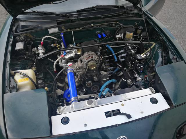
Here is my engine bay as it stands, could give you a few ideas.
If you need any information, fell free to shoot me a PM.
Good luck man.
I am the french man, with the green 13b PP miata
Good to see people all around the world taking on the same project !
It will be long and difficult and painful, but it will be all worth it in the end. The miata is a great car to begin with, once you've added a few mods.
But when you put a rotary in it, it becomes a ******* laugh machine !!
One thing you should think about RIGHT NOW is cooling. The NA miata hasn't much of bumper surface for many coolers. So you gotta be creative.
On the track, i could't do 3 laps without having the oil at 140�C because i didn't design it the right way from the beginning (mine is a PP mind you, with 250whp so more heat than a sideport engine).
First, i put the FC oil cooler in front of the radiator, in the bumper mouth : it blocked the airflow completely : oil and water overheated badly. One thing i noticed though, in N/A form, my engine had its water at 120�C a few times, and the water seals hold perfectly. Without a turbo, it is much much more forgiving.
Then i tried a big square 30 row oil cooler behind the radiator : water temp was steady but oil reaches 120�C after a few bursts on the road. And i didn't even took it to the track with this setup.

Remember that the rotary puts 30% of its heat in the oil, so oil cooling is as important as water.
Last thing i am going to try, is trim down my radiator so i can put my oil cooler next to it, in order to have fresh air to both coolers (google : honda civic radiator on a miata). I just hope the smaller radiator will be able to evacuate all the calories. Ducting is the key here. You have to block ALL the path the air can take around your cooler, because it will. By the way, just don't try to run without the belly ban. It acts as a duct for the radiator. Even wih yours at an angle.
Here is my engine bay as it stands, could give you a few ideas.

If you need any information, fell free to shoot me a PM.
Good luck man.


Joined: Oct 2001
Posts: 6,279
Likes: 728
From: Florence, Alabama
one of my 13B-rew motors is running in a miata... around 400/500 rwhp.
we faced, of course, the same problem. the answer is to put the radiator in the trunk.
more rear weight too. bonus
we faced, of course, the same problem. the answer is to put the radiator in the trunk.
more rear weight too. bonus
Full Member
Joined: Feb 2013
Posts: 116
Likes: 0
From: France
Anything that can help increase the delta P around the rads basically.
Hood vents come in last for me. You can do so much by just ducting the stock setup. It is a real fishnet in stock form.
If you look at cutting holes in the hood though, have a look at singular motorsports miata hood vents.
Hood vents come in last for me. You can do so much by just ducting the stock setup. It is a real fishnet in stock form.
If you look at cutting holes in the hood though, have a look at singular motorsports miata hood vents.

Joined: Mar 2001
Posts: 31,857
Likes: 3,243
From: https://www2.mazda.com/en/100th/
we had cooling problems on a stock engine miata on the track. we did do the singular Motorsports hood vents, and if they did anything it was marginal.
we were contemplating using a bigger radiator and mounting it like an FD, but then car got hit, and totaled, which fixed the problem
we were contemplating using a bigger radiator and mounting it like an FD, but then car got hit, and totaled, which fixed the problem
Thread Starter
Junior Member
Joined: Jan 2018
Posts: 47
Likes: 12
From: Germany
This topic has evolved into great and valueable discussion!
@whizzybang @Howard Coleman CPR Thanks for sharing your experience!
I'm surprised that you had cooling issues despite your setup which looks pretty solid, big aluminium radiator, big oil cooler and all.
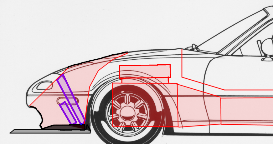
Here's my idea, I will try and build a dedicated isolated cooling passage that vents through the hood like so. Luckily there is tons of space available with the engine being so small.
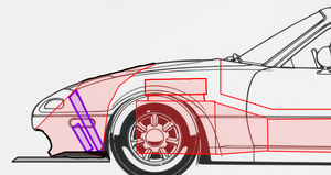
The bumper could be cut away downwards to make room for more air volume to pass through the tunnel.
As for the engine intake I plan to use those turn-signal-intakes below the headlights.
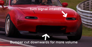
Hopefully this will help enough. What do you guys think?
Anyway, not many news here. I am currently busy keeping my current car running in order to regularily hit the track this season. It's a simple car and most maintenance doesnt take much time, but the ******* stock engine, man. I'm rebuilding it the second time this year because it keeps eating excessive amounts of oil. Anyway, I built a tube bender to fabricate a cage so there is some progress.
There is something I need help with; so I want to clearance the tips of my rotors for high rpm, but I have yet to find some details on the procedure. I've read that 0.003 inches should be adequate. But I'm wondering if the tip should bemachined down at an angle so that the change in surface is like a slope instead of a 'step'.
Here's a shitty picture of what I mean.
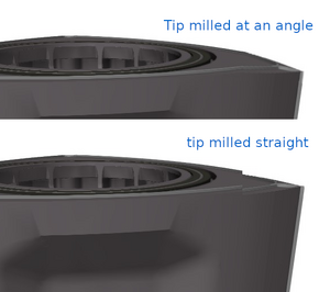
The irons are being ground flat at the moment. Results look amazing.
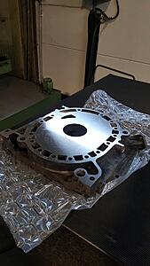
Afterwards the coolant ring grooves will be machined into them, followed by gas nitriding.
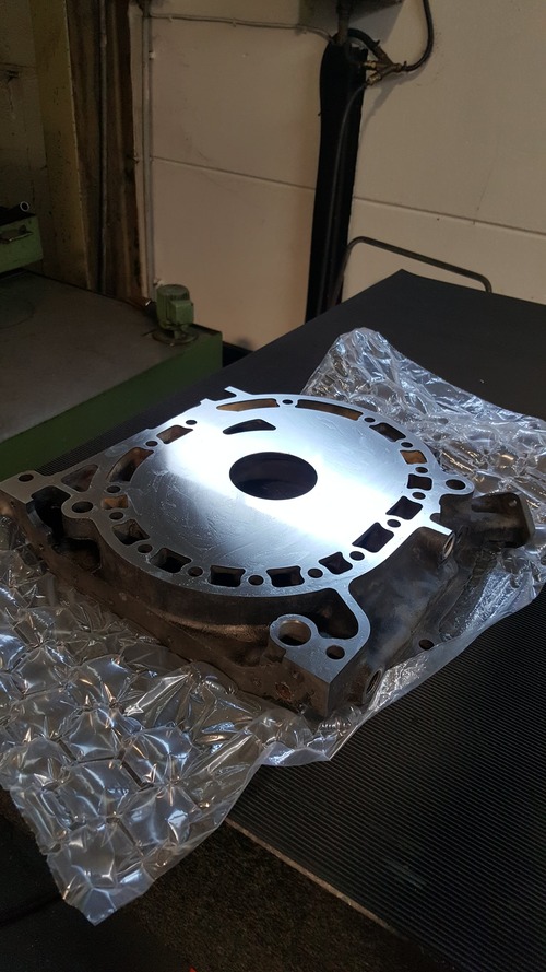
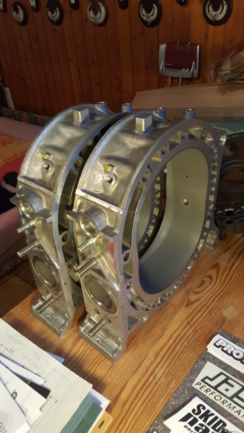
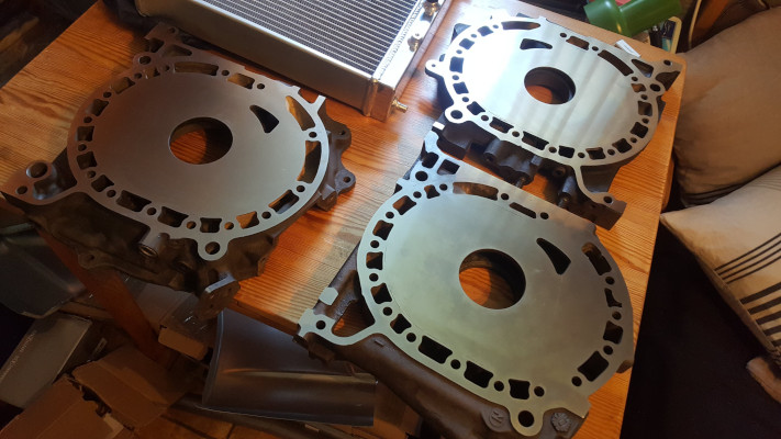
New housings have arrived as well. Big $$$

Another interesting thing I found out. So I bought two Kia Sportage front differentials because they are said to have a compatible ring & pinion but with shorter gear ratios. Just what I need! It turns out that out of the two I opened, they had different ratios: 4.44 and 4.77. Really cool!
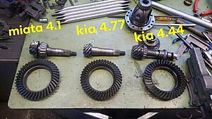
That's it for now. Albeit slowly, things are moving. Peace!
@whizzybang @Howard Coleman CPR Thanks for sharing your experience!
I'm surprised that you had cooling issues despite your setup which looks pretty solid, big aluminium radiator, big oil cooler and all.
Here's my idea, I will try and build a dedicated isolated cooling passage that vents through the hood like so. Luckily there is tons of space available with the engine being so small.
The bumper could be cut away downwards to make room for more air volume to pass through the tunnel.
As for the engine intake I plan to use those turn-signal-intakes below the headlights.

Hopefully this will help enough. What do you guys think?
Anyway, not many news here. I am currently busy keeping my current car running in order to regularily hit the track this season. It's a simple car and most maintenance doesnt take much time, but the ******* stock engine, man. I'm rebuilding it the second time this year because it keeps eating excessive amounts of oil. Anyway, I built a tube bender to fabricate a cage so there is some progress.
There is something I need help with; so I want to clearance the tips of my rotors for high rpm, but I have yet to find some details on the procedure. I've read that 0.003 inches should be adequate. But I'm wondering if the tip should bemachined down at an angle so that the change in surface is like a slope instead of a 'step'.
Here's a shitty picture of what I mean.

The irons are being ground flat at the moment. Results look amazing.
Afterwards the coolant ring grooves will be machined into them, followed by gas nitriding.
New housings have arrived as well. Big $$$
Another interesting thing I found out. So I bought two Kia Sportage front differentials because they are said to have a compatible ring & pinion but with shorter gear ratios. Just what I need! It turns out that out of the two I opened, they had different ratios: 4.44 and 4.77. Really cool!

That's it for now. Albeit slowly, things are moving. Peace!
Joined: Mar 2001
Posts: 31,857
Likes: 3,243
From: https://www2.mazda.com/en/100th/
for the milling, 0.003" is so small it almost doesn't matter
and B turn signal intake is too small, unless you can really duct it well https://www.linkedin.com/pulse/air-d...cle-card_title
and B turn signal intake is too small, unless you can really duct it well https://www.linkedin.com/pulse/air-d...cle-card_title
spoon!
Joined: Sep 2002
Posts: 1,208
Likes: 50
From: Dousman, WI
How I personally did tip milling is with a cup grinder on a milling machine arbor. I put the rotor centered on a rotary table and shimmed one side of the rotary table up a couple thou from parallel to the mill table, then rotated the rotary table around taking very light grinds. I don't remember the exact reference I was using but my basic strategy was very carefully move the mill bed up fractions of a thou at a time up until the area being ground was "a bit" shy of the oil rings. So, the angled cut style. I copied the setup I saw in the Jim Downing written book that's floating around somewhere basically - I agree that either way would probably work, but that way seemed "better" to me.
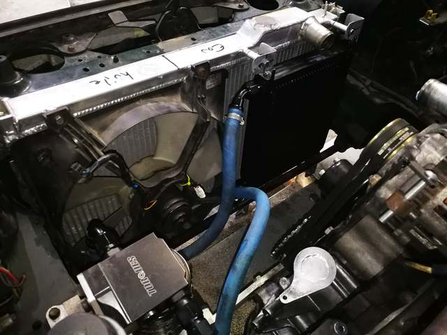
edit: Oh yeah, looking at the setup you have with the coolers... something to watch for with stacking the coolers is that they're not robbing air from each other. With the oil cooler simply in front of the radiator like that, if the oil cooler doesn't have its own duct feeding it, air will just go around it... and if it is, it'll rob air from the radiator. I'm going to call the ducting feeding the radiator as a plenum because when the car is moving it's basically a reservoir of pressurized air... the factory competition manual for the 1st gen RX-7 suggests the oil cooler horizontally on the floor of the plenum instead of stacked in front of the radiator like you have pictured is worth something like 20 degrees of oil temperature, especially if the exit from the oil cooler is going to the low pressure area created by the front splitter. Later factory race cars put the oil coolers on the sides of the plenum vertically, with the air exiting out into the wheel wells. With both the oil cooler and radiator on the back of the plenum, ideal would be something like a V-mount setup done with intercoolers... where the coolers have a parallel shot at air rather than series.
edit: Oh yeah, looking at the setup you have with the coolers... something to watch for with stacking the coolers is that they're not robbing air from each other. With the oil cooler simply in front of the radiator like that, if the oil cooler doesn't have its own duct feeding it, air will just go around it... and if it is, it'll rob air from the radiator. I'm going to call the ducting feeding the radiator as a plenum because when the car is moving it's basically a reservoir of pressurized air... the factory competition manual for the 1st gen RX-7 suggests the oil cooler horizontally on the floor of the plenum instead of stacked in front of the radiator like you have pictured is worth something like 20 degrees of oil temperature, especially if the exit from the oil cooler is going to the low pressure area created by the front splitter. Later factory race cars put the oil coolers on the sides of the plenum vertically, with the air exiting out into the wheel wells. With both the oil cooler and radiator on the back of the plenum, ideal would be something like a V-mount setup done with intercoolers... where the coolers have a parallel shot at air rather than series.
Last edited by Kenku; May 18, 2019 at 09:25 AM.
Joined: Mar 2001
Posts: 31,857
Likes: 3,243
From: https://www2.mazda.com/en/100th/
i used a GSL-SE cooler and it bolts to the radiator support right behind the round tube that goes between the frame rails. i choose this primarily because the FC cooler ended up really low, and i wanted the cooler not to be removed by the first off track....
i made a simple duct that just goes from the undertray to the cooler, out of a cereal box, and it just works great. at some point a real duct is an option, although my Triumph used a cardboard radiator duct from the factory. next project is to make the roll cage from wood....
anyways, temps are rock solid, works way better than it should considering the effort and testing
Joined: Mar 2001
Posts: 31,857
Likes: 3,243
From: https://www2.mazda.com/en/100th/
part 2, with the stupid miata, we ran the giant Koyo radiator, put an oil cooler up front, ran the hood vents and switched to E85, and we could keep it to 105c...
the FC is Lock Lobster on here, due to class rules, we were on the same tires, he got 160hp/2900lbs and we were 136hp/2360lbs.
note 2, if you start this
about when the cars are leaving the paddock, it happens to synch right up to the other video
the FC is Lock Lobster on here, due to class rules, we were on the same tires, he got 160hp/2900lbs and we were 136hp/2360lbs.
note 2, if you start this
spoon!
Joined: Sep 2002
Posts: 1,208
Likes: 50
From: Dousman, WI
I'm thinking about trying an Afco 80420 oil cooler on the next race car - 25.6"x10"x2" double pass cooler should be reasonable sized, and easier than finding a used 1st or 2nd gen oil cooler in good condition these days.
Thread Starter
Junior Member
Joined: Jan 2018
Posts: 47
Likes: 12
From: Germany
Thanks for the hints about the cooling setup. I understand now that the way I intended isnt going to work very well. I'll think of an alternative solution.
@Kenku as always great help from you, thanks. I think I will do the cut angled as well. I have a mill but not a rotary table. However I have a lathe and might try to do it this way.
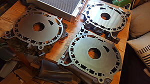
Some small updates here, the irons are now fully ground flat. Next step is to CNC the coolant seal grooves into them.
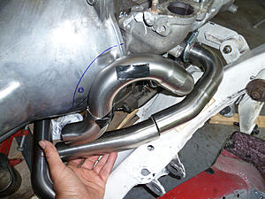
Work on the header has continued, thanks to the help of a very good friend of mine who happens to be somewhat of an exhaust expert. So far we came up with this solution pictured below. It requires some more chassis cutting but we can't figure out a better way with the space we have. The primaries lengths should be about equal and they connect at about 480mm. Slightly above recommended length for a bridge port, but we expect this to keep peak power down since we aren't going to rev above 8500rpm (due to regular steel seals)
@Kenku as always great help from you, thanks. I think I will do the cut angled as well. I have a mill but not a rotary table. However I have a lathe and might try to do it this way.
Some small updates here, the irons are now fully ground flat. Next step is to CNC the coolant seal grooves into them.
Work on the header has continued, thanks to the help of a very good friend of mine who happens to be somewhat of an exhaust expert. So far we came up with this solution pictured below. It requires some more chassis cutting but we can't figure out a better way with the space we have. The primaries lengths should be about equal and they connect at about 480mm. Slightly above recommended length for a bridge port, but we expect this to keep peak power down since we aren't going to rev above 8500rpm (due to regular steel seals)

Thread Starter
Junior Member
Joined: Jan 2018
Posts: 47
Likes: 12
From: Germany
Looks good!
I would not machine the water grooves in those plates, but machine the grooves in the rotor housings instead.
On used rotor housings the flat mating surface can be a little bit pitted / corroded, and by machining water grooves in there you create a nice new surface for the o-rings to seal against.
It also allows the iron's to be ground or lapped again if required.
Full Member
Joined: Feb 2013
Posts: 116
Likes: 0
From: France
This is how I did my exhaust. Could give you some ideas.
<a href="https://www.casimages.com/i/1507140601128772013443263.jpg.html" target="_blank" title="Mon image"><img src="https://nsm08.casimages.com/img/2015/07/14//1507140601128772013443263.jpg" border="0" alt="Mon image" /></a>
<a href="https://www.casimages.com/i/1507140601048772013443262.jpg.html" target="_blank" title="Mon image"><img src="https://nsm08.casimages.com/img/2015/07/14//1507140601048772013443262.jpg" border="0" alt="Mon image" /></a>
<a href="https://www.casimages.com/i/1507140600558772013443261.jpg.html" target="_blank" title="Mon image"><img src="https://nsm08.casimages.com/img/2015/07/14//1507140600558772013443261.jpg" border="0" alt="Mon image" /></a>
Joined: Feb 2017
Posts: 511
Likes: 54
From: San Leandro California
I think cutting the water seal groves in the housings is far better than the plates. Easier to do too. Water seal groves on the irons are usually where the seal fails because of the iron cracking. I think thats the reason why mazda went back to the groove in the housing on the rx8.
Thread Starter
Junior Member
Joined: Jan 2018
Posts: 47
Likes: 12
From: Germany
Hmm yes I thought about machining the grooves into the housing before. Your points are very valid. But I think it will be harder to perfectly align the housing into the cnc machine. On the irons its easy because they have flat surfaces all around. I will see what we can do
@whizzybang thanks for sharing those exhaust pics. I see you have alot more clearance thanks to the tubular subframe.
@whizzybang thanks for sharing those exhaust pics. I see you have alot more clearance thanks to the tubular subframe.
Joined: Mar 2001
Posts: 31,857
Likes: 3,243
From: https://www2.mazda.com/en/100th/
Supplies are probably getting low.
The dealer with the best price I found online (Werner Mazda in NH) said they were unavailable. As soon as a couple weeks ago the "add to cart" button for the housings was active. Their website has a 10% off code that I hoped would work.
The next best one I bookmarked (*** Mazda in FL) said they will come from Japan in about 8-12 weeks. I jumped on that.
I might be mistaken but I'm not sure the GSL-SE or an equivalent 13B before 1986 was sold in Europe unless they got the 3rd gen Cosmo. Not saying they won't be able to order the housings, but they're going to be harder to find.
Last edited by j_tso; Jun 1, 2019 at 02:28 PM.