
Megasquirt Setting up MS3x to control 6ports, VDI, and FPR solenoids

Thread Starter
Joined: Jul 2002
Posts: 3,219
Likes: 8
From: Washington State
Setting up MS3x to control 6ports, VDI, and FPR solenoids
I've got 3 solenoids I'd like to control with the MS3x:
1) FPR solenoid (using an OEM solenoid from the emissions rack)
2) 6 port solenoid (aftermarket 12v 1.25amp solenoid)
2) VDI port solenoid (aftermarket 12v 1.25amp solenoid)
I'm wondering how to set up and configure the outputs, both in terms of wiring and software config.
Will the MS3 be able to trigger these solenoids directly, or will a diode + relay be required?
Are these outputs providing 12v or ground activation?
Which outputs are ideal for these - the MS site only says "use spare outputs on the daughterboard." (How to MegaSquirt your FC RX-7)
The 6ports and VDI are based on RPM and manifold pressure (engine load) - would those be configured as VVT? (Megasquirt-3 MS3 Variable valve timing (VVT / VANOS))
Thanks in advance!
~Geoff
Joined: Feb 2001
Posts: 29,798
Likes: 128
From: London, Ontario, Canada
All of those solenoids can be switched just using spare injector outputs. One side of the solenoid to 12V switched, the other side to the injector output. You don't need a diode as those outputs are clamped. The injector outputs switch to ground.
The aux port and VDI solenoids have both a load and RPM activation but aren't PWM'd in any way by the stock ECU, they are just on-off. So in Generic IO, you'd just set them up with two parameters as the activation criteria. Load (MAP) value and RPM.
What's the FPR solenoid switching?
The aux port and VDI solenoids have both a load and RPM activation but aren't PWM'd in any way by the stock ECU, they are just on-off. So in Generic IO, you'd just set them up with two parameters as the activation criteria. Load (MAP) value and RPM.
What's the FPR solenoid switching?
Thread Starter
Joined: Jul 2002
Posts: 3,219
Likes: 8
From: Washington State
Awesome, thanks Aaron!
FPR solenoid switches during cranking to help reduce vapor lock:
Source: http://www.diyautotune.com/tech_arti...zda_fc_rx7.htm
FPR solenoid switches during cranking to help reduce vapor lock:
Other Things the (stock) ECU Controls
...
Fuel pressure regulator: One of the relay control circuits on the daughter board can be used to activate the fuel pressure solenoid while cranking, which can help reduce vapor lock.
...
Fuel pressure regulator: One of the relay control circuits on the daughter board can be used to activate the fuel pressure solenoid while cranking, which can help reduce vapor lock.
Joined: Feb 2001
Posts: 29,798
Likes: 128
From: London, Ontario, Canada
I've never found that necessary. A high pressure fuel system like EFI basically eliminates the problem of vapor lock anyway. The priming pulse opens the injectors enough so any bubbles around the pintel are gone.
I guess if you want to implement it, it won't hurt. Just seems unnecessary.
Mazda implemented a lot of hacks with the stock ECU to solve specific issues instead of programming around them. Understandable considering the limited nature of the L-Jetronic but we've moved on. For example, we don't require 3 different valves to increase the idle speed of the engine.
The FPR solenoid was in a way a carry over from the earlier carbureted cars which had a hot start motor which would tug on a cable to nudge the throttle open a little on hot starts.
Thread Starter
Joined: Jul 2002
Posts: 3,219
Likes: 8
From: Washington State
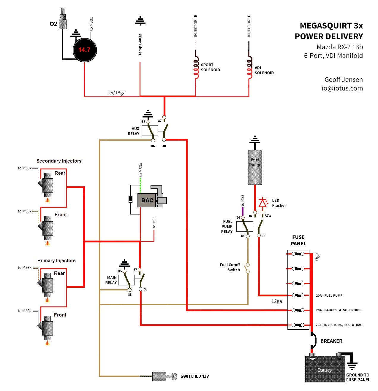
Wiring diagram
A dude on MegaSquirt Facebook group confirmed you can use the injectors to directly ground the solenoids. After reading more into it - You're absolutely right, FPR solenoid not required. All modern computers compensate for this with post-start variables. Thanks for pointing that out!
So here's the diagram I've drawn up for my power grid. I'm not using an eFan (yet) but have run the wires for down-the-road, so this diagram does not include that.
Aaron - I noticed you were using the Main Relay circuit power as a switched signal to provide +12v on pin 86 of the relays. After thinking about this for a bit, I started getting worried about voltage drop across the circuit with the addition of all that extra wire (especially up to the e-fan relay) on the circuit that powers the injectors, ecu, and sensors.
As such, I've made some changes to your power grid by using the switched 12v from the stock ECU harness to trigger all of the primary relays, as well as added an additional fuse and relay to split the load of the circuit and fuse the components on a more granular level.
Feedback and is welcome:
Trending Topics
Joined: Feb 2001
Posts: 29,798
Likes: 128
From: London, Ontario, Canada
Aaron - I noticed you were using the Main Relay circuit power as a switched signal to provide +12v on pin 86 of the relays. After thinking about this for a bit, I started getting worried about voltage drop across the circuit with the addition of all that extra wire (especially up to the e-fan relay) on the circuit that powers the injectors, ecu, and sensors.
The primary reason I tie it all off of the main relay is because that means only one connection from the car goes to the ECU wiring: switched 12V. And by removing the main relay, just like removing the stock EGI fuse/relay, the entire system is disabled. I like to have the main relay go to a terminal strip which then connects to all 12V switched feeds for the system. Make sure to use a good 40A relay though you shouldn't be drawing anywhere near that current.
As such, I've made some changes to your power grid by using the switched 12v from the stock ECU harness to trigger all of the primary relays, as well as added an additional fuse and relay to split the load of the circuit and fuse the components on a more granular level.
Thread Starter
Joined: Jul 2002
Posts: 3,219
Likes: 8
From: Washington State
I'm not talking about just the voltage drop or load from the relays, but from the length of wire run TO the relays, which is just as important to factor in. Over the length of the circuit you describe, which i would estimate to be between 20-25ft depending on where you mount the relays, it would probably be between 1.6v (16ga circuit) to 3.2volts (18ga circuit). That would mean the circuit voltage at the end of the line would be 10.4v to 8.8v, down from 12v, just from wire alone!
This may not be enough voltage drop to effect the function of all the systems they're powering, but regardless i would prefer to have switched 12v coming from one source (the car's switched 12v) and have the relays specifically control the power grid to the items they're controlling. seems a more straightforward system.
Less voltage drop is always better, especially when it comes to the system's core components!
EDIT: I looked at your diagrams again, and realized I was assuming you were mounting the efan relay up front by the fan (not sure why i thought that). If you mount all the relays together, you're literally only looking at a foot or less of extra wire, which would be .127v drop assuming 18ga wire
Joined: Feb 2001
Posts: 29,798
Likes: 128
From: London, Ontario, Canada
You're over thinking it. The voltage drop is not nearly as high as you assume because the resistance of the wire is damn near 0 ohm (obviously not exactly zero, but close enough). That's why we build wire out of copper rather than say, string. It is not the wire you need to worry about but the quality of your connections that will cause any voltage drop.
You can wire things however you feel is best for your application. Keep in mind that the car's wiring is probably the limiting factor, being 25+ years old.
I mount the e-fan relay(s) always up at the front of the car and run 12 gauge feeds to them to power the fans. Those relays are clicking on and off constantly which would be very annoying to have in the cabin. OEMs mount them in the same location for the same reason and use much thinner wire typically (cost and weight savings).
If you're curious as to how I set things up, see my Cosmo video where I install an MS3-Pro from scratch:
How To Megasquirt Your 2nd Gen RX-7: Installation Video and Resources
Thread Starter
Joined: Jul 2002
Posts: 3,219
Likes: 8
From: Washington State
Not sure i would agree. Voltage drop over wire is a major factor to consider. After many hours of discussion with Mark at MAD Electric, he got me thinking a lot more about this.
Especially if you're running the fan relay up front sharing the same circuit as the fuel injectors, you're robbing the fuel injectors of several volts.
There is a bunch of information to read up on in his tech articles:
MadElectrical.com - Electrical Tech
Especially if you're running the fan relay up front sharing the same circuit as the fuel injectors, you're robbing the fuel injectors of several volts.
There is a bunch of information to read up on in his tech articles:
MadElectrical.com - Electrical Tech
Joined: Feb 2001
Posts: 29,798
Likes: 128
From: London, Ontario, Canada
That's the beauty of physics. While you may disagree, Ohms law remains constant and physics doesn't lie.
If you think there is a large voltage drop across a 12 gauge wire when running a reasonably sized e-fan (say, NOT a Taurus fan which draws stupid high currents) then you can simply measure it. Connect up fan to 12V battery via a 15 foot length of 12 gauge wire. Place + meter probe at + battery terminal, place - probe at fan terminal. Record voltage. It will be very, very low. That's the voltage drop.
Use the proper wire gauge for the load and the length of wire isn't a concern. Length is one of those factors you considering when choosing a wire gauge.
Thread Starter
Joined: Jul 2002
Posts: 3,219
Likes: 8
From: Washington State
What i'm disagreeing with is your wiring methodology, not Ohm's law, fwiw.
I wasn't just pulling imaginary numbers out of nowhere, I was using voltage drop calculations, which are in fact based on physics.
http://www.calculator.net/voltage-drop-calculator.html
I wasn't just pulling imaginary numbers out of nowhere, I was using voltage drop calculations, which are in fact based on physics.
http://www.calculator.net/voltage-drop-calculator.html
Junior Member
Joined: Feb 2012
Posts: 30
Likes: 0
From: Bakersfield Ca
Using your calculator, I still end up with 0.32 volt drop when configured for a standard electric fan setup. 10 amps at 10 feet of 12 gauge wire. Aarons right. You are over thinking it. That kind of voltage drop is nothing to think of.
Thread Starter
Joined: Jul 2002
Posts: 3,219
Likes: 8
From: Washington State
Taking voltage drop into consideration is not over thinking it, but essential when planning a circuit.
To properly engineer a circuit, each wire, each device, each connector must be considered especially when voltage dependent sensors are in the circuit.
At first I was saying the same, but when I talked with Mark at MAD electric he clued me in on how to plan circuits in this fashion.
See the link above for in depth details on circuits.

Thread
Thread Starter
Forum
Replies
Last Post
trickster
2nd Generation Specific (1986-1992)
25
Jul 1, 2023 04:40 PM
turbo-minivan
General Rotary Tech Support
69
Feb 4, 2016 12:29 AM