
Megasquirt Scratched my PCB, now no sync!

Scratched my PCB, now no sync!
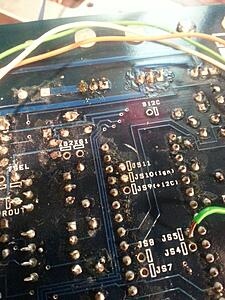
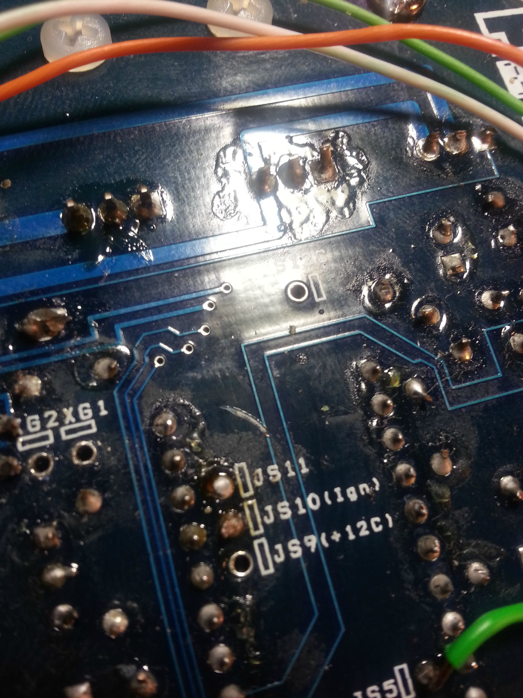
Hi guys. I finished soldering my input/outputs on my zeal car and my MS board was finally 100% done. I was using my trusty snips to trim the jumper leads, slipped, and scratched my board. I tried connecting to my PC and it refuses to sync. Firmware loader also doesnt see the MS.
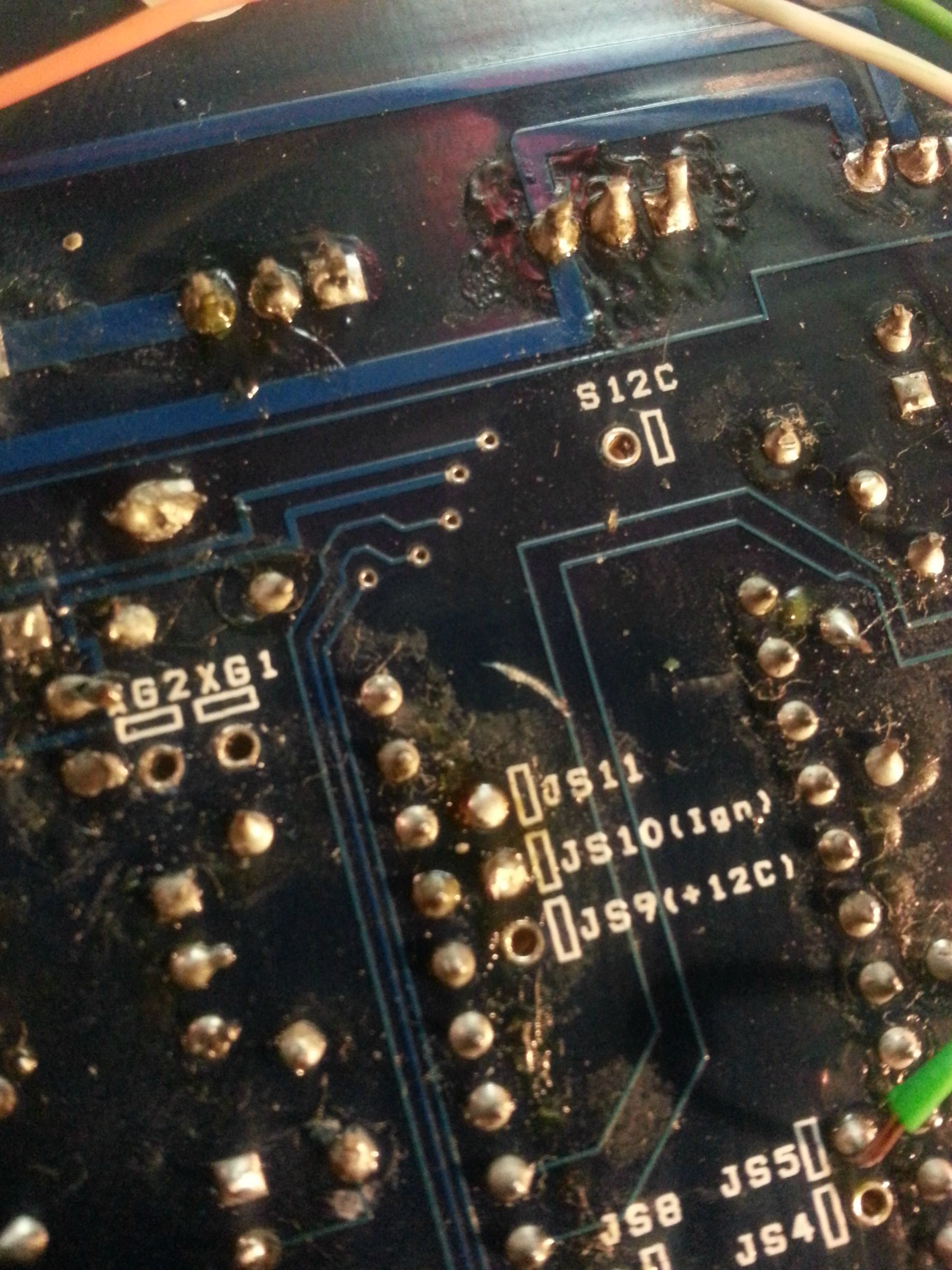
The only things I've done since I was last able to sync was remove the MS2 processor card, solder jumpers to JS0, JS1, and JS11. NOW, I jumpered JS1 instead of JS2 to the Zeal inputs and tried to boot the MS before I realized I was supposed JS2. Pretty sure this wont cause any issues, but I don't know for sure. I also jumpered the Zeal outputs to SPR2-4.
Does the PCB look like the culprit? Is it salvageable? I was so close to being done!
Thanks,
Alex
The only things I've done since I was last able to sync was remove the MS2 processor card, solder jumpers to JS0, JS1, and JS11. NOW, I jumpered JS1 instead of JS2 to the Zeal inputs and tried to boot the MS before I realized I was supposed JS2. Pretty sure this wont cause any issues, but I don't know for sure. I also jumpered the Zeal outputs to SPR2-4.
Does the PCB look like the culprit? Is it salvageable? I was so close to being done!

Thanks,
Alex

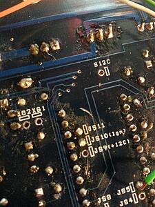
scrape off the resin to expose the copper trace lead and carefully solder a jumper wire to it. if you don't understand then just have an electronics shop do the bypass.
if it's easier for you, you can also find both ends of the trace and solder your jumper wire to them instead.
if it's easier for you, you can also find both ends of the trace and solder your jumper wire to them instead.
Got it!
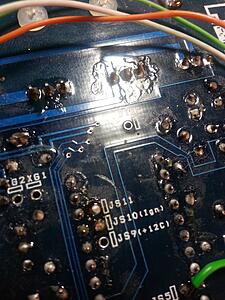
I used a razor blade and scraped the lacquer off and dropped a dob of solder on the two points of the trace. I checked continuity between the CPU pin and where the trace led. I got nothing initially and only 1.2 ohm after. Plugged everything up and its sync'd like old times.
Thanks!
I used a razor blade and scraped the lacquer off and dropped a dob of solder on the two points of the trace. I checked continuity between the CPU pin and where the trace led. I got nothing initially and only 1.2 ohm after. Plugged everything up and its sync'd like old times.
Thanks!

Thread
Thread Starter
Forum
Replies
Last Post
[For Sale] Scratch & Dent, Used, and Open-Box Sale!
SakeBomb Garage
Vendor Classifieds
5
Aug 9, 2018 05:54 PM

