
Megasquirt Resistors


Rotary Enthusiast
Joined: Oct 2001
Posts: 1,022
Likes: 4
From: Ontario, Canada
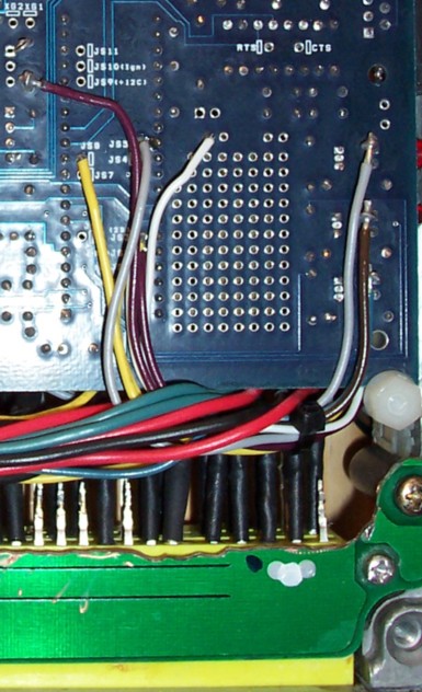
I ran my set flat against the board along the front edge, below the led's. The legs were bent to attach to the 5v side of the led resistors, and then the opposite side of the led's. I've attached a board pic of a similar install, taken from http://megasquirt.sourceforge.net/ex...tup-gmdis.html. I'm not keen on the mounting arrangement shown, as the resistor standing up as shown will be more susceptible to damage and vibration, but it certainly shows the connections clearly enough.
Trending Topics
RX-7 Alumni
Joined: Oct 2002
Posts: 1,140
Likes: 1
From: Spacecenter Houston
Originally Posted by muythaibxr
on a v3 board it'll be slightly different. I will have to take a pic as it appears that I don't have any.
If you look close at the pic, you can see I made a little loop on the bottom side of the board and soldered the wire into it.
Did you mount yours in the stock computer box? Also thankyou for the pic and the help. One last question was the adapter you made for the harness to make it plug n play hard to make. I already have the plug from an ecu ad wires. Is there anything I should know before I do it?
RX-7 Alumni
Joined: Oct 2002
Posts: 1,140
Likes: 1
From: Spacecenter Houston
Originally Posted by lowkee33
Did you mount yours in the stock computer box? Also thankyou for the pic and the help. One last question was the adapter you made for the harness to make it plug n play hard to make. I already have the plug from an ecu ad wires. Is there anything I should know before I do it?
It was alot of work, but I suppose if I started building more it would be easier--but still alot of work.
I'd recommend running all the CAS wires in shielded pairs. I'm in the process right now of re-doing those 4 wires with shielded.

Thread
Thread Starter
Forum
Replies
Last Post