
Megasquirt New MS3Pro NA build


Thread Starter
Senior Member
Joined: Sep 2013
Posts: 301
Likes: 34
From: asheville
New MS3Pro NA build
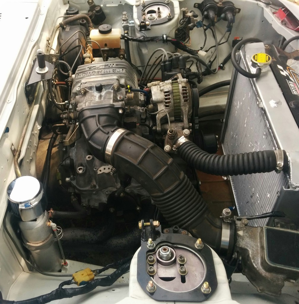
I am a newbie when it comes to Megasquirt I thought I would do a build thread on my project. It is a race car so it will be normally aspirated which is ironic for a team made up almost entirely of turbo engineers� My car is a FB with a 13B, the block is a S3 with a big street port and header, it has S4 rotors just because they were the best rotors I had available when I was building the engine. Up until now I have been running the engine with a S4 intake that had the secondary injector bosses plugged, and running with the 2 injector GSL-SE ECU. As part of the MS install I will be switching to a S5 intake and 4 yellow RX8 injectors. I also plan to activate the VDI valve with an electric solenoid, but if it doesn't work or if I don't see any significant advantage I will just wire it open.
My setup
MS3 Pro
13B large street port with S5 intake and electronically activated VDI
4 RX8 injectors 450cc I believe
All GM sensors including TPS and 1 bar MAP sensor
2 LC2 wideband controllers so I can potentially tune each rotor or set up an alarm if either rotor starts running lean
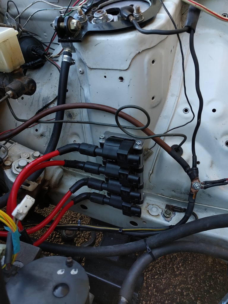
LS2 coils
Standard S4 CAS
Pretty much everything else is stripped down to the bare minimum I am really trying to make sure all the wiring is clean and robust, for endurance racing you want everything to be dead reliable.
If anyone has a good street ported NA 13B base tune I would be interested, seems like everyone else is running a turbo.

My setup
MS3 Pro
13B large street port with S5 intake and electronically activated VDI
4 RX8 injectors 450cc I believe
All GM sensors including TPS and 1 bar MAP sensor
2 LC2 wideband controllers so I can potentially tune each rotor or set up an alarm if either rotor starts running lean
LS2 coils
Standard S4 CAS


Pretty much everything else is stripped down to the bare minimum I am really trying to make sure all the wiring is clean and robust, for endurance racing you want everything to be dead reliable.
If anyone has a good street ported NA 13B base tune I would be interested, seems like everyone else is running a turbo.
Thread Starter
Senior Member
Joined: Sep 2013
Posts: 301
Likes: 34
From: asheville
I do have one question about rev limits. The max I can set the rev limiter is 9000 RPM which should be adequate for me in this endurance racing application, but what about guys with peripheral ported engines? Maybe it is because I have the stroke set to rotary, but 9K wouldn't even be in the midrange of a modern superbike so how do they do it?
MegaSquirt Mod
Joined: Sep 2004
Posts: 4,721
Likes: 1
From: Maryland
I do have one question about rev limits. The max I can set the rev limiter is 9000 RPM which should be adequate for me in this endurance racing application, but what about guys with peripheral ported engines? Maybe it is because I have the stroke set to rotary, but 9K wouldn't even be in the midrange of a modern superbike so how do they do it?
Thread Starter
Senior Member
Joined: Sep 2013
Posts: 301
Likes: 34
From: asheville
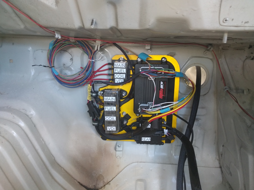
I am making good progress, I just need to finish wiring in the coils, weld some fittings on my fuel rail, and plumb the fuel lines. My original idea was to order all the connectors unassembled so I could run the wires all the way to the connector without any splices. The problem is that every one of the different connectors seems to have some kind of intricate detail on how to assemble them which makes it a pain. The only one that completely defeated me was the LS coil connectors which I was having a nightmare trying to assemble them, in the end I punted and ordered a new set of assembled connectors with pigtails. If I do it over again I will order everything with pigtails, I can solder just fine and have plenty of adhesive lined shrink tubing.
I am happy that I splurged on ordering a printer that can make heat shrink tube labels, it is really nice to have everything labeled.
I have the ECU talking to my computer and have started the basic programming. I have 2 potentially useful .msq files, one from a friend who runs a MS3 Pro on an SCCA first gen with an RX8 motor, and the one from Aaron Cake. The RX8 file has a lot of problems for me since he tweaked a bunch of the inputs and outputs to work with the RX8 wiring harness, Aarons file works pretty well for me since mine is a very pure Megasquirt install even using all GM sensors. The only difference is that I am using the LS coils, and my car is normally aspirated. One option is to copy the NA tables for fuel and spark from the RX8 file, the other option would be to rescale Aarons tables to work with the NA engine. Is there an easy way to remove the boosted parts of the fuel and spark tables and rescale them to work with my NA motor?
I am happy that I splurged on ordering a printer that can make heat shrink tube labels, it is really nice to have everything labeled.


I have the ECU talking to my computer and have started the basic programming. I have 2 potentially useful .msq files, one from a friend who runs a MS3 Pro on an SCCA first gen with an RX8 motor, and the one from Aaron Cake. The RX8 file has a lot of problems for me since he tweaked a bunch of the inputs and outputs to work with the RX8 wiring harness, Aarons file works pretty well for me since mine is a very pure Megasquirt install even using all GM sensors. The only difference is that I am using the LS coils, and my car is normally aspirated. One option is to copy the NA tables for fuel and spark from the RX8 file, the other option would be to rescale Aarons tables to work with the NA engine. Is there an easy way to remove the boosted parts of the fuel and spark tables and rescale them to work with my NA motor?
For an NA engine, I would play with whatever VE map you have to get the car to hold a stable idle and use VE analyzer to autotune the rest of the map on the street. Make sure the target AFRs are correct and you're wideband calibration is correct and just drive it like you would. Autotune works pretty fast and you can get a pretty good fuel map in less than an hour. I don't use autotune for tuning in boost, but for an NA car, there's very little risk. If you notice whole areas of the map are lean or rich, make broad adjustments and keep driving it. VE Analyzer is awesome!
Thread Starter
Senior Member
Joined: Sep 2013
Posts: 301
Likes: 34
From: asheville
I do plan to use the autotune to get my tune initially dialed in. even though this is a race car the shop I work out of is in a gated complex and I can make laps around some of the buildings in a nice oval, I even have is saved as a track in RaceChrono so I can get lap times and if I am up or down on my best lap. I also have a shop lined up a few miles from where I work on the car that has a dyno for final tuning, one of my team members bought a Mustang dyno so in the future I will be able to have pretty much unlimited tuning time but it will be at least 6 months before he has all of the infrastructure in place to make the dyno functional.
The question that I had was how is the best way to take all the boosted bins out of a table and rescale it for normally aspirated operation? Pretty much everything you can find for a rotary is for a boosted one, I would love to run a turbo since we actually build the EFR turbos here at our plant in Asheville and I was involved in some of the early development, but I don't see that happening any time soon.
The question that I had was how is the best way to take all the boosted bins out of a table and rescale it for normally aspirated operation? Pretty much everything you can find for a rotary is for a boosted one, I would love to run a turbo since we actually build the EFR turbos here at our plant in Asheville and I was involved in some of the early development, but I don't see that happening any time soon.
See attached. You change the values on the y-axis to end at 100 and evenly spaced values and it extrapolates new values based on JUST the values under what you previously had. For example, if you had a max of 300 kpa on your map and changed it to 100, it would stretch JUST the 0-100 portion of the old map over the entire 16x16 map.
Trending Topics
Thread Starter
Senior Member
Joined: Sep 2013
Posts: 301
Likes: 34
From: asheville
I was able to rescale my maps to work with my NA application. I have spent so many years working with various engineering software that can do amazing things but requires a lot of input to get results it is sometimes confusing when something is so simple, I feel like there should be more steps involved…
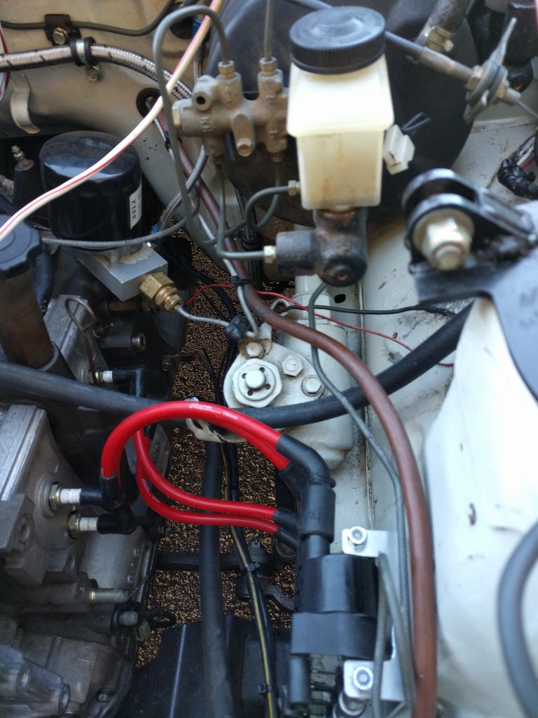
I have the car running now. Thursday night was bad, I couldn't get the injectors to fire in test mode and then when I turned on the fuel pump my welded up S5 fuel rail leaked like a sieve… Then I discovered that to test the injectors I have to unplug the fuel pump but enable it in software to activate the fuel pump relay which powers the injectors. After that I was able to test the injectors and coils, everything fires in the correct sequence so yay. I rigged up a fuel rail by cutting the mounting feet off a S4 rail that I had and mounted it with some clamps, I just did what I should have done a long time ago and ordered some bare extrusion and fittings to make my own fuel rail from scratch.
It’s amazing how far things can be off and these engines will still run, my first startup it ran, although badly, with the hose to the MAP sensor disconnected. I hooked up the hose and it started and ran, as Aaron always says his base map is really rich, I had to take a ton of fuel out right away but now I can start tuning.
I do have 2 issues now
My tach doesn't work, I had this issue before on another car where voltage from the ECU tach out signal was not high enough for the Autogauge tach. We never were able to get the tach working from the tach out wire, we had to rig up a diode bridge on the power wires to the EDIS. In my case I believe that the signal going to my LS coils is still only 5 volts so I don't know what will make it work in this case. I am not too worried since Holley is giving me one of their digital dashes which will use CAN but I may not have it before the race I have coming up in 3 weeks.
The other stranger issue is that the engine doesn't shut off when I turn the switch off, I have to turn the switch off, back on and then off a second time to get the engine to shut off. It is a race car so the system is as simple as possible with just a simple toggle switch to apply power to the main relay and a starter button.
I had a similar issue where the ECU switch wouldn't kill the engine. My issue was resolved by using the switch to kill all 12V to the engine and ECU. Coils, fan, injectors, BC solenoid, idle valve, everything. I believe when the ECU can still be backpowered by the 12V accessories if they remain powered.
Joined: Feb 2001
Posts: 29,798
Likes: 128
From: London, Ontario, Canada
I do have 2 issues now
My tach doesn't work, I had this issue before on another car where voltage from the ECU tach out signal was not high enough for the Autogauge tach. We never were able to get the tach working from the tach out wire, we had to rig up a diode bridge on the power wires to the EDIS. In my case I believe that the signal going to my LS coils is still only 5 volts so I don't know what will make it work in this case. I am not too worried since Holley is giving me one of their digital dashes which will use CAN but I may not have it before the race I have coming up in 3 weeks.
My tach doesn't work, I had this issue before on another car where voltage from the ECU tach out signal was not high enough for the Autogauge tach. We never were able to get the tach working from the tach out wire, we had to rig up a diode bridge on the power wires to the EDIS. In my case I believe that the signal going to my LS coils is still only 5 volts so I don't know what will make it work in this case. I am not too worried since Holley is giving me one of their digital dashes which will use CAN but I may not have it before the race I have coming up in 3 weeks.
The other stranger issue is that the engine doesn't shut off when I turn the switch off, I have to turn the switch off, back on and then off a second time to get the engine to shut off. It is a race car so the system is as simple as possible with just a simple toggle switch to apply power to the main relay and a starter button.
Or your switch is bad.


Nice build!
On the topic of Tach output, are you saying the MS3Pro Tach Output wire doesn't drive the FC tach? I'm running a similar setup (ms3pro and LS2 coils) and I want to make sure I wire the Tach correctly.
On the topic of Tach output, are you saying the MS3Pro Tach Output wire doesn't drive the FC tach? I'm running a similar setup (ms3pro and LS2 coils) and I want to make sure I wire the Tach correctly.
Thread Starter
Senior Member
Joined: Sep 2013
Posts: 301
Likes: 34
From: asheville
I have 4 relays in the system which get their power from an 8 gauge wire connected to the off side of the master cutoff switch which splits into 4 12 gauge wires to each relay. Even worse than the fact that it would sometimes not stop running when I turned off the switch is the fact that the engine didn't stop when you turned off the master power cutoff which is an instant tech fail. The main relay powers the ECU and 2 wideband controllers and is the trigger signal for the coil relay, it is triggered by the on/off switch, the fuel relay powers the injectors and BAC and is triggered by the fuel pump wire from the ECU, the coil relay provides power to my 4 LS coils and is triggered by the main relay, the VDI relay provides power to the electric solenoid to activate the variable intake it is triggered by one of the auxiliary outputs from the ECU. Whichever relay was causing a problem it doesn't matter now, I put an 80amp continuous duty relay in the 8 gauge wire so when I flip the switch it guarantees that all power is killed to everything going to the ECU.
The tach output was way easier, I just had it disabled. I am not using a stock tach, it is just an old Autogauge 5 inch tach, once I turned the tach output on it worked fine.
That brings up the far more subtle and more interesting programming problem that I had. When I started this build I decided to get wideband O� sensors for both rotors, I want to eventually tune each individual rotor, but I figured that even from the start it would be interesting to log both rotors. Once I got the car running but the idle was a little rough, and watching the AFR gauges the rear rotor was reading lean and erratic, the logs showed that once it was running at higher power and RPM the difference between the front and rear rotor was less, but still there and it always came back once I was back at idle. I did the obvious first and switched both primary and secondary injectors front to rear, made no difference. My next step was to check if I had a bad plug or something with the ignition, I put the ECU in test mode and it fired the front rotor leading and trailing plugs just fine but when I tried to fire the rear leading plug it fired the front leading again. That was really strange but once I looked in the settings I saw that it was set to wasted spark instead of coil on plug, I changed that and all plugs fire as they should and it runs much better. The rear rotor was always running with retarded timing but as the power went up it got better because the split was less.
Joined: Feb 2001
Posts: 29,798
Likes: 128
From: London, Ontario, Canada
That brings up the far more subtle and more interesting programming problem that I had. When I started this build I decided to get wideband O� sensors for both rotors, I want to eventually tune each individual rotor, but I figured that even from the start it would be interesting to log both rotors. Once I got the car running but the idle was a little rough, and watching the AFR gauges the rear rotor was reading lean and erratic, the logs showed that once it was running at higher power and RPM the difference between the front and rear rotor was less, but still there and it always came back once I was back at idle. I did the obvious first and switched both primary and secondary injectors front to rear, made no difference. My next step was to check if I had a bad plug or something with the ignition, I put the ECU in test mode and it fired the front rotor leading and trailing plugs just fine but when I tried to fire the rear leading plug it fired the front leading again. That was really strange but once I looked in the settings I saw that it was set to wasted spark instead of coil on plug, I changed that and all plugs fire as they should and it runs much better. The rear rotor was always running with retarded timing but as the power went up it got better because the split was less.
Thread Starter
Senior Member
Joined: Sep 2013
Posts: 301
Likes: 34
From: asheville
I had a couple of maps to play with, I ended up using yours after I worked out how to rescale the tables to take out the boosted areas. The first time I loaded your map I set the ignition correctly and enabled the tach output, but when I went back to the baseline I missed those changes. Car runs great now, and should only run better as I get more data for my tuning.
Thread Starter
Senior Member
Joined: Sep 2013
Posts: 301
Likes: 34
From: asheville
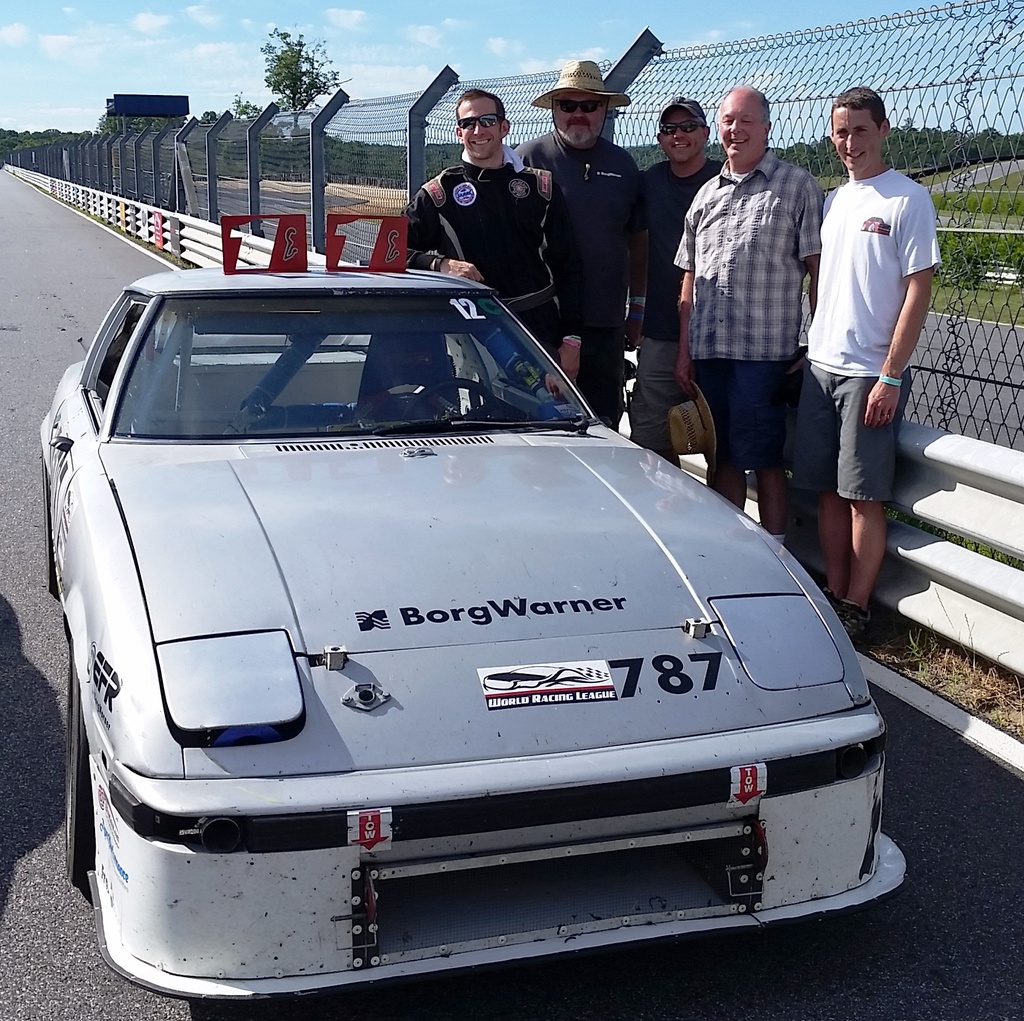
So far I am pretty happy with the results on this car, last Wednesday we took the car to the dyno and made way more power than almost anybody estimated, then we raced over the weekend. We won both days, set fast lap of the weekend, and a new track record for these kind of cars. Not too bad for one of these old cars, it doesn't help that almost nobody is doing development on normally aspirated rotaries anymore but I learned a few tricks that I was able to use.


Junior Member
Joined: Jan 2013
Posts: 40
Likes: 0
From: Montreal
Thoroughly enjoyed this thread as I have a similar setup (S5 motor with RX8 yellow in primary and secondary) which I am currently wrapping up a Megasquirt build on. This is in an FB which was previously running a stock S5 NA swap with oem FC ecu and harness.
Wondering if you would be interested in sharing maps?
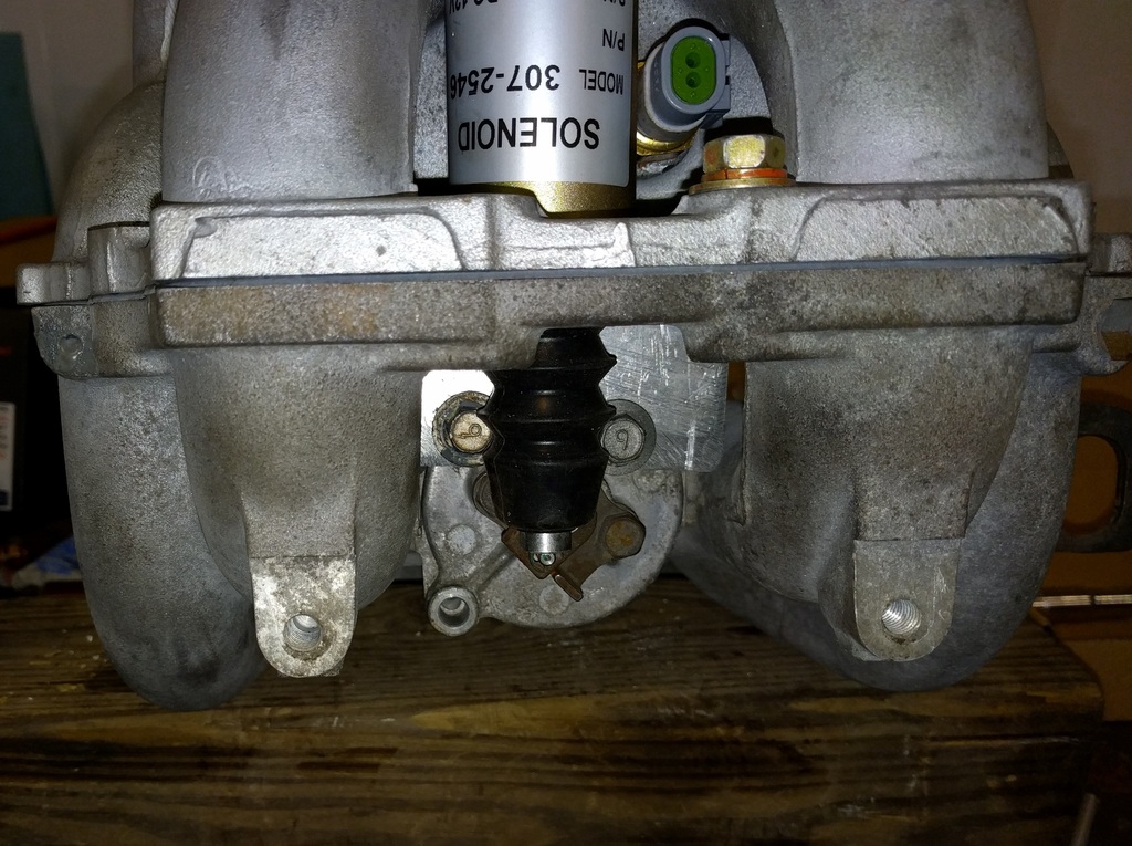
Also wondering if you are successful running the aux ports and vdi with the solenoid model pictured above? I'm still running the air pump but I like the simplicity of this setup. Although those solenoids looks pricey!
Wondering if you would be interested in sharing maps?
Also wondering if you are successful running the aux ports and vdi with the solenoid model pictured above? I'm still running the air pump but I like the simplicity of this setup. Although those solenoids looks pricey!

Thread Starter
Senior Member
Joined: Sep 2013
Posts: 301
Likes: 34
From: asheville
On a very conservative Mustang dyno we made just over 200hp at the wheels, on a Dynojet it would have been more. I am friends with one of the top E prod engine builders who happens to live in the same city as I do, so I know how quite a bit about how those run.
Thread Starter
Senior Member
Joined: Sep 2013
Posts: 301
Likes: 34
From: asheville
It makes no difference in my car. At the VIR 24hr we got a crack in our header and the heat caused all kind of problems, including getting the aluminum bracket I made for my solenoid hot enough that it broke. When I built it I put a long stud sticking out right under the lever for just this situation so I tie wrapped it open and we couldn't tell any difference. Since then we have raced with it wired open and still set fast lap of the race, with the close ratio Miata gears in the transmission it never gets low enough to be beneficial.

Thread
Thread Starter
Forum
Replies
Last Post
Boriquaguerrero
1st Generation Specific (1979-1985)
5
Mar 26, 2016 12:49 PM
wallyrx7
1st Generation Specific (1979-1985)
14
Mar 19, 2016 11:49 AM