
Megasquirt mega squirt out puts.


mega squirt out puts.
New to the mega squirt I was thinking of picking up a ms2 with the zeal board and harness.
My question is can I set a out put to a electronic gauge that I do t have a sensor for? What I was thinking was using GM sensors then be able to use the output on the ms2 to run a old electronic HKS gauge. Is this possible the hks gauges are metric readings.
My question is can I set a out put to a electronic gauge that I do t have a sensor for? What I was thinking was using GM sensors then be able to use the output on the ms2 to run a old electronic HKS gauge. Is this possible the hks gauges are metric readings.
Joined: Feb 2001
Posts: 29,798
Likes: 128
From: London, Ontario, Canada
Driving gauges with an MS2 isn't going to happen in any easy way because the MS2 lacks generic PWM outputs.
If you want to drive gauges, and have a lot of I/O, then MS3 with MS3x is the best option.
If you want to drive gauges, and have a lot of I/O, then MS3 with MS3x is the best option.
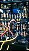
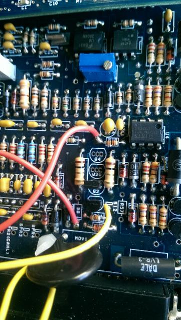
Since I have a thread going already I'll post this here. Got my ms2 v3.0 board. Has the zeal card installed already. I was going to use the BAC valve. The write up says to remove R19 Q4 Q20 R39 and D8. My board came pre assembled without the extra shielded wire for the CAS.
How ever my board still has R39 and R19 in place. Should I remove those two resistors or keep them in place? The idle in is soldered to the lead on R19. D8 is removed and idle out is connected to the banded side of d8 spot.
How ever my board still has R39 and R19 in place. Should I remove those two resistors or keep them in place? The idle in is soldered to the lead on R19. D8 is removed and idle out is connected to the banded side of d8 spot.
Joined: Feb 2001
Posts: 29,798
Likes: 128
From: London, Ontario, Canada
According to the schematic, with Q4 and Q20 removed, R39 is just hanging in the wind and doesn't make a difference.
Looking at the Zeal instructions ( Assembling the Zeal Engineering Daughterboard for MegaSquirt ) your board appears to be connected correctly. Leaving R19 in won't make a difference because the Zeal is connected to the "input" side of the resistor. The output side is just hanging there unconnected.
Sucks about the shielded wire. I'm emailing DIY Auto Tune shortly so I'll as them if the harness could include it.
Okay cool I was not sure if it would make a difference. Next pulling wires through my harness to group them my db37 pin out does not match what I have. None of the diagrams I have found look like my wire harness. My grounds are in position 8-14 and pin 17 for the sensor grounds.
What I was reading in the diagrams from the msextra manual is that 15-19 are the grounds and 7 should be the black and white stripe sensor ground. Should I change it in the db37 according to the diagram in the ms2V3.0 hardware guide from ms extra? All other sensor locations correlate with that diagram.
Trending Topics
Did some more searching and it appears it does not matter as long as the sensors are all grounded to one single wire back to the megasquirt. Depending on when the harness was made will dictate the ground positions. The different wire diagrams I've been seeing all have been updated and the grounds were the only thing changed. At least that's how I see it according to this article.
www.diyautotune.com/tech_articles/grounds.html
www.diyautotune.com/tech_articles/grounds.html
Joined: Feb 2001
Posts: 29,798
Likes: 128
From: London, Ontario, Canada
Correct. Depending on where you got your harness, they may have placed the sensor ground on a different pin. Just as long as all the sensors are grounded to one wire, and all the other grounds run to the engine block. I like to consolidate all those grounds at the grounding block on the fuse panel and then bring out two nice 12 gauge ground wires from that to the block.
I did not purchase a fuse pannel with a separate ground block. Should I get a seperate ground block or just use a existing stud. I was planning on running it in my factory FB ecm bracket.
Joined: Feb 2001
Posts: 29,798
Likes: 128
From: London, Ontario, Canada
Have you read the documentation? All Megasquirt install docs recommend grounding directly to the engine or the battery. Never the car body. Since you don't have a ground block, run all your grounds out to the engine and ground at the same place. Factory ground is a good place though a bit inaccessible.
If you ground to the body you will get noise on the CAS and voltage offsets on sensors.
If you ground to the body you will get noise on the CAS and voltage offsets on sensors.
I was thinking of a separate ground block insulated from the car body to run the multiple wires to then run some 12gauge wires to the the engine bay. But at that rate might as well just run all the grounds to the engine I guess.
Joined: Feb 2001
Posts: 29,798
Likes: 128
From: London, Ontario, Canada
It's preference. I like to put a ground block at the fuse panel because it's convenient and there are other things requiring ground at the ECU (wideband, for example). But that must be isolated from chassis then wired directly to the battery or engine. Preferably engine.
Okay looks like I should pick up a new fuse block the one I had only has one positive input so I would need to run the ecu power on a seperate block anyway so a fuse block with a ground will be on my shopping list.
Joined: Feb 2001
Posts: 29,798
Likes: 128
From: London, Ontario, Canada
My Megasquirt writeup would help a lot with many of these questions even though it's geared towards installing in a 2nd gen.
How To Megasquirt Your 2nd Gen RX-7
How To Megasquirt Your 2nd Gen RX-7
're read everything over a few times and realised where I was getting overly confused. Jumping between your diagrams and DIY information on the zeal board left me fairly confused but I think I got it now. Using aux output 3 for my efan relay. Pin 25 and 27 for the added vr conditioner stock ms locations for the NE side of the CAS and then I still need to run a jumper to get my 12v tach signal off the board.
After I realised all that everything is making 10x more sense.
After I realised all that everything is making 10x more sense.

Thread
Thread Starter
Forum
Replies
Last Post
Megasquirt timing map and EGt ?? what do you guys think
immanuel__7
Megasquirt Forum
3
Aug 22, 2015 09:34 PM
79+80_rx-7
1st Generation Specific (1979-1985)
30
Oct 18, 2002 02:44 PM