Megasquirt Forum Area is for discussing Megasquirt EMS

Megasquirt launch wiring

Thread Tools
 
Search this Thread
 
Old May 12, 2011 | 01:03 PM
  #1  
gabs88gxl's Avatar
Thread Starter
Retard
Tenured Member 05 Years
iTrader: (3)
 
Joined: Apr 2007
Posts: 461
Likes: 0
From: Denver
launch wiring

Im looking around on how to wire the launch control in to my 2.2. I seen that you us jp1 pin 4. how do i run this do i run pin 4 to a swtich an a ground to the other side of the switch. or do i have to run in to the board. Using a input jp1 pin 4 and a output some where in the board. please let me know thank you
Reply
Old May 12, 2011 | 03:39 PM
  #2  
papiogxl's Avatar
What's the point??
Tenured Member: 20 Years
iTrader: (6)
 
Joined: Oct 2005
Posts: 995
Likes: 0
From: Omaha, NE


This circuit is what you would build.
Reply
Old May 16, 2011 | 01:15 AM
  #3  
gabs88gxl's Avatar
Thread Starter
Retard
Tenured Member 05 Years
iTrader: (3)
 
Joined: Apr 2007
Posts: 461
Likes: 0
From: Denver
so do i just take the wire from jp1/4 to the switch n take the resistor an the diode to the tps 5verf
Reply
Old May 17, 2011 | 01:43 AM
  #4  
FC3Sdrift's Avatar
Displacement Replacement
Tenured Member 15 Years
iTrader: (5)
 
Joined: Apr 2007
Posts: 1,502
Likes: 0
From: St. Thomas
can you use the 5v from the proto area?
what about the zeal daught would the inputs work on that for launch control???
i've spend over 4 hours tonight readin about this
Reply
Old May 17, 2011 | 03:34 PM
  #5  
gabs88gxl's Avatar
Thread Starter
Retard
Tenured Member 05 Years
iTrader: (3)
 
Joined: Apr 2007
Posts: 461
Likes: 0
From: Denver
Originally Posted by FC3Sdrift
can you use the 5v from the proto area?
what about the zeal daught would the inputs work on that for launch control???
i've spend over 4 hours tonight readin about this
thanks a good question cause that will use less wire ill talk to ken or someone at diy maybe they can help us out
Reply
Old May 17, 2011 | 04:37 PM
  #6  
FC3Sdrift's Avatar
Displacement Replacement
Tenured Member 15 Years
iTrader: (5)
 
Joined: Apr 2007
Posts: 1,502
Likes: 0
From: St. Thomas
yeah i' like to figure it all out, I have the diodes and resistor, i just dont want to go and start messing with stuff and fry something
Reply
Old May 18, 2011 | 12:30 AM
  #7  
gabs88gxl's Avatar
Thread Starter
Retard
Tenured Member 05 Years
iTrader: (3)
 
Joined: Apr 2007
Posts: 461
Likes: 0
From: Denver
Originally Posted by FC3Sdrift
yeah i' like to figure it all out, I have the diodes and resistor, i just dont want to go and start messing with stuff and fry something
thank you atleast im not the only one with that fear
Reply
Old May 18, 2011 | 05:38 PM
  #8  
SPIRITED_DRIVER07's Avatar
Never Enough Turns
Tenured Member 05 Years
 
Joined: Feb 2007
Posts: 107
Likes: 0
From: IL
I also have been wondering the same thing
Reply
Old May 18, 2011 | 06:08 PM
  #9  
FC3Sdrift's Avatar
Displacement Replacement
Tenured Member 15 Years
iTrader: (5)
 
Joined: Apr 2007
Posts: 1,502
Likes: 0
From: St. Thomas
Originally Posted by SPIRITED_DRIVER07
I also have been wondering the same thing
HaHaHa i was like "sweet someone new replied maybe they know" guess not
Reply
Old May 18, 2011 | 06:19 PM
  #10  
gabs88gxl's Avatar
Thread Starter
Retard
Tenured Member 05 Years
iTrader: (3)
 
Joined: Apr 2007
Posts: 461
Likes: 0
From: Denver
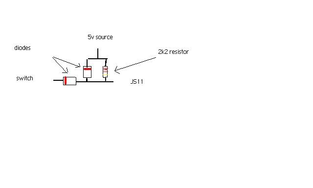
well i got it i talked to matt at diy today an we kind went over it. Pretty much just get two diodes the 1n4001 an one 2.2k resistor. run it like the diagram but run it to jp1 pin 4 an if you are using the zeal board you can jump off the 5volt or jp1pin 8 put that bad boy in an boom it worked lol. ill make a little write up to help out
Reply
Old May 18, 2011 | 08:50 PM
  #11  
FC3Sdrift's Avatar
Displacement Replacement
Tenured Member 15 Years
iTrader: (5)
 
Joined: Apr 2007
Posts: 1,502
Likes: 0
From: St. Thomas
if i can use the 5v off the zeal board i take it i can use the 5v from the proto area??? to keep it cleaner
Im using the 3.0 board
i'll just build it and see how it works
Reply
Old May 19, 2011 | 02:48 AM
  #12  
gabs88gxl's Avatar
Thread Starter
Retard
Tenured Member 05 Years
iTrader: (3)
 
Joined: Apr 2007
Posts: 461
Likes: 0
From: Denver
yeah im pretty sure as long as its a 5volt it will work just make sure u use the resistor an the diodes. cause even with mine ran to the 5volt on my zeal i push the push button an launch lights up on the bottom of megatune.
Reply
Old May 19, 2011 | 08:10 AM
  #13  
papiogxl's Avatar
What's the point??
Tenured Member: 20 Years
iTrader: (6)
 
Joined: Oct 2005
Posts: 995
Likes: 0
From: Omaha, NE
5v is 5v as far as the ms is concerned, especially for this circuit. The ms just needs to see the voltage drop from 5 volts to (essentially) zero.
Reply
Old Jun 25, 2011 | 06:51 PM
  #14  
.::evil inside::.'s Avatar
Senior Member
Tenured Member: 20 Years
 
Joined: Jun 2004
Posts: 263
Likes: 2
From: Australia
Did you end up putting a little writeup together? I haven't touched my ms for a while and my brain isn't computing how to build the said circuit. Pictures would help me greatly even pics instead of writeup would be awesome.
Reply
Old Jul 6, 2011 | 04:36 PM
  #15  
FC3Sdrift's Avatar
Displacement Replacement
Tenured Member 15 Years
iTrader: (5)
 
Joined: Apr 2007
Posts: 1,502
Likes: 0
From: St. Thomas
i finally got around to making the launch circuit
heres a little video i made trying it out at 4k

http://www.youtube.com/watch?v=EyNxuNdraAY
Reply
Old Jul 7, 2011 | 08:51 AM
  #16  
.::evil inside::.'s Avatar
Senior Member
Tenured Member: 20 Years
 
Joined: Jun 2004
Posts: 263
Likes: 2
From: Australia
nice work mate.

Any pics?
Reply
Old Jul 7, 2011 | 10:42 AM
  #17  
FC3Sdrift's Avatar
Displacement Replacement
Tenured Member 15 Years
iTrader: (5)
 
Joined: Apr 2007
Posts: 1,502
Likes: 0
From: St. Thomas
this is how i set mine uop in my proto area, its basically what the diagram shows to do


Reply
Old Jul 8, 2011 | 04:55 AM
  #18  
.::evil inside::.'s Avatar
Senior Member
Tenured Member: 20 Years
 
Joined: Jun 2004
Posts: 263
Likes: 2
From: Australia
Thanks for that mate, so the switch is connected to ground?
Reply
Old Jul 8, 2011 | 09:35 AM
  #19  
FC3Sdrift's Avatar
Displacement Replacement
Tenured Member 15 Years
iTrader: (5)
 
Joined: Apr 2007
Posts: 1,502
Likes: 0
From: St. Thomas
yeah, just grounds out the circuit

i forgot to say i just used the spare pin aaron cake uses for his E fan circuit, goes to pin 25 on the db37
Reply
Old Jul 9, 2011 | 01:20 PM
  #20  
.::evil inside::.'s Avatar
Senior Member
Tenured Member: 20 Years
 
Joined: Jun 2004
Posts: 263
Likes: 2
From: Australia
Geez, can't believe I even needed to ask those questions. My brain really is out of gear, thanks for putting up with my momentary stupidity.

would you be able to post a screen capture of your launch/flat shift settings?
Reply
Related Topics
Thread
Thread Starter
Forum
Replies
Last Post
toplessFC3Sman
2nd Generation Specific (1986-1992)
6
Mar 20, 2018 01:54 PM
DocHoliday89
3rd Generation Specific (1993-2002)
5
Oct 12, 2015 07:42 PM
FC3S_nataku
2nd Generation Specific (1986-1992)
4
Sep 15, 2015 12:36 PM
cosmo7
West RX-7 Forum
2
Sep 14, 2015 09:47 PM


All times are GMT -5. The time now is 07:37 AM.