
Megasquirt Got it started, problem with RPM signal and probably something else


Thread Starter
Joined: Mar 2007
Posts: 1,029
Likes: 0
From: Appleton, WI
Got it started, problem with RPM signal and probably something else
Hello,
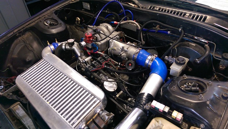
13B-turbo, s4 engine with s5 rotating assembly
LS1 coilpacks
MS2V3.57 with zeal
1000/1600cc injectors
90mm throttlebody and OEM tps from VH45DE
Car will start after some cranking, I'm able to keep it running with the throttle for a minute or two and then it dies.
I noticed that while holding the RPMs steady, I'm getting some spikes of 0 RPM.
I believe I set the potentiometers on the board to the minimum setting per the megamanual during the install but I can't be positive.
Can anyone suggest some troubleshooting steps to fix my rpm signal and get it to idle?
.msl:
http://www.filedropper.com/2015-05-23154605
.msq:
http://www.filedropper.com/2015-05-26184907
Thanks!
-Nathan
Thread Starter
Joined: Mar 2007
Posts: 1,029
Likes: 0
From: Appleton, WI
Everything checks out okay with the megasquirt, pretty sure this is due to noise in the CAS wiring somewhere. I have the CAS wiring split out of the shielding at the firewall bulkhead, and the coils are almost mounted on top of the CAS, so there's two likely sources.
I already gave up and ordered the trigger wheel kit from FFE.
I already gave up and ordered the trigger wheel kit from FFE.
Joined: Feb 2001
Posts: 29,798
Likes: 128
From: London, Ontario, Canada
Your ignition wires pass directly over the CAS.
You probably know this, but the CAS has two VR sensors inside. Magnets wrapped with many turns of copper wire. Which make wonderful little amplifying antennas for HV cables pulsing right above them. Bet if you scoped the VR lines you'd find big spikes in concert with the ignition firing.
Just a word of warning from tuning a few big throttle bodies: Expect about 25% more idle PWM needed to maintain a steady idle, with a richer mixture. Now that the progressive throttle is gone and all ports are being fed, wall wetting goes all to hell. Same goes for accel enrichment. About 50% more fuel needed.
Thread Starter
Joined: Mar 2007
Posts: 1,029
Likes: 0
From: Appleton, WI
Your ignition wires pass directly over the CAS.
You probably know this, but the CAS has two VR sensors inside. Magnets wrapped with many turns of copper wire. Which make wonderful little amplifying antennas for HV cables pulsing right above them. Bet if you scoped the VR lines you'd find big spikes in concert with the ignition firing.
Just a word of warning from tuning a few big throttle bodies: Expect about 25% more idle PWM needed to maintain a steady idle, with a richer mixture. Now that the progressive throttle is gone and all ports are being fed, wall wetting goes all to hell. Same goes for accel enrichment. About 50% more fuel needed.
You probably know this, but the CAS has two VR sensors inside. Magnets wrapped with many turns of copper wire. Which make wonderful little amplifying antennas for HV cables pulsing right above them. Bet if you scoped the VR lines you'd find big spikes in concert with the ignition firing.
Just a word of warning from tuning a few big throttle bodies: Expect about 25% more idle PWM needed to maintain a steady idle, with a richer mixture. Now that the progressive throttle is gone and all ports are being fed, wall wetting goes all to hell. Same goes for accel enrichment. About 50% more fuel needed.
Actually don't have an IAC of any sort at the minute...sounds like I'm in for more surprises. This car is a track toy, so drivability and idle quality aren't a huge priority.
Thanks for the help.
Thread Starter
Joined: Mar 2007
Posts: 1,029
Likes: 0
From: Appleton, WI
Well, I unbolted the coils and just set them on the inner fender above the brake MC. Car fired right up and happily idled with a little throttle input at 1200rpm until it died out again 20 seconds later. Zero on the lost count gauge...time to start tuning! Thanks guys.
Funny thing is, I just moved the coils OFF the the side of the strut tower to make room for the new charge piping.
Funny thing is, I just moved the coils OFF the the side of the strut tower to make room for the new charge piping.
Joined: Feb 2001
Posts: 29,798
Likes: 128
From: London, Ontario, Canada
The CAS is very sensitive to noise.
Glad you got it going!
That throttle body is perfectly suited to constant moderate-full throttle operation. Nice thing about a different throttle body is the new full range TPS an the fact the shaft O-rings don't leak like hell.
Glad you got it going!
That throttle body is perfectly suited to constant moderate-full throttle operation. Nice thing about a different throttle body is the new full range TPS an the fact the shaft O-rings don't leak like hell.
Trending Topics
Thread Starter
Joined: Mar 2007
Posts: 1,029
Likes: 0
From: Appleton, WI
Okay, a little more insight into the "something else" that is giving me problems...
I was having problems getting the coolant temp sensor to read correctly. I tried recalibrating it several times with different numbers I found online, to no avail, before pulling it and testing the resistance of the sensor to build my own curve. The numbers I measured fit the curve provided by DIYautotune perfectly, meaning the calibration is not the problem.
Meanwhile, the TPS reads perfectly and sweeps cleanly with the engine off, but bounces 1-3% with the engine on. This is enough to kick in TPSdot AE and doesn't allow me to properly set up AE.
With the DB37 plugged into the megasquirt, my multimeter shows continuity between chassis ground and the ground pins on the TPS and CLT. With the DB37 unplugged, the multimeter doesn't beep, but it does show a reading...I believe it was around 1860 ohms.
So...it appears my sensor ground is bleeding over into chassis ground somewhere, or my sensor ground is contaminated with chassis ground through some component. I'm going to print out the grounds section of the manual and pour over the harness with a multimeter...any guesses on likely places I should look first?
Last edited by The Shaolin; Jun 5, 2015 at 09:47 AM.
Joined: Feb 2001
Posts: 29,798
Likes: 128
From: London, Ontario, Canada
By not reading correctly, what do you mean?
Jittering?
Or offset up or down a number of degrees?
I'm mentally picturing this but they way I see it, the sensor ground with the connector unplugged should not have any reading to chassis ground (or a massively high one in the order of 100s of megaohms) unless you have tied them together somewhere. Now they are tied together on the MS board.
Try unplugging all the sensors and measure again.
Thread Starter
Joined: Mar 2007
Posts: 1,029
Likes: 0
From: Appleton, WI
The other end of this wire terminates on the strut tower and has the coil ground on it...is this a problem? The battery is in the backseat and is grounded to frame only.
By not reading correctly, what do you mean?
Jittering?
Or offset up or down a number of degrees?
I'm mentally picturing this but they way I see it, the sensor ground with the connector unplugged should not have any reading to chassis ground (or a massively high one in the order of 100s of megaohms) unless you have tied them together somewhere. Now they are tied together on the MS board.
Try unplugging all the sensors and measure again.
Jittering?
Or offset up or down a number of degrees?
I'm mentally picturing this but they way I see it, the sensor ground with the connector unplugged should not have any reading to chassis ground (or a massively high one in the order of 100s of megaohms) unless you have tied them together somewhere. Now they are tied together on the MS board.
Try unplugging all the sensors and measure again.
According to my pinout, it appears DB37 pins 7-9 were tied together inside the harness and run to sensor ground, and pins 15-19 are grounded on the engine. Is this correct?
Thread Starter
Joined: Mar 2007
Posts: 1,029
Likes: 0
From: Appleton, WI
I just went through every ground on the car and cleaned them all up and greased them. None of them were really bad but some were definitely less than ideal.
I started the car and warmed it up until my dash coolant gauge read 130�F.
The Megasquirt CLT bounced between 67 and 68 and then rose to 71, but no higher.
TPS signal is still bouncy, but might be a little better now, I dunno.
I'm gonna make sure I don't have the chassis ground and signal ground wires flipped in my bulkhead connector, but then I'm out of ideas.
Joined: Feb 2001
Posts: 29,798
Likes: 128
From: London, Ontario, Canada
In all the DIYAutoTune harnesses I've seen, the grounds each lead to their own pin. Then tie together on the board itself. I just went back on a few of my pictures to verify this. That's not to say your harness isn't different so you should pop the DB37 case and check.
Some jitter on the TPS is normal but it should only be 1 or two counts.
Make sure the 5V reference to your sensors is actually 5V.
Some jitter on the TPS is normal but it should only be 1 or two counts.
Make sure the 5V reference to your sensors is actually 5V.
Thread Starter
Joined: Mar 2007
Posts: 1,029
Likes: 0
From: Appleton, WI
In all the DIYAutoTune harnesses I've seen, the grounds each lead to their own pin. Then tie together on the board itself. I just went back on a few of my pictures to verify this. That's not to say your harness isn't different so you should pop the DB37 case and check.
Some jitter on the TPS is normal but it should only be 1 or two counts.
Make sure the 5V reference to your sensors is actually 5V.
Some jitter on the TPS is normal but it should only be 1 or two counts.
Make sure the 5V reference to your sensors is actually 5V.
Speaking of DB37...one of the secondary injector wires fell out of the back of the connector. I can see the pin inside where it was once crimped, but it's inside the case and I can't reach it...any hints?
I'll check the voltage at the sensors tomorrow.
Joined: Feb 2001
Posts: 29,798
Likes: 128
From: London, Ontario, Canada
Where did this harness come from? The fact an injector wiring fell out (!!!) doesn't bode well. Intermittent connections at the other pins could explain your issues.
I'm not sure how to extract those pins. Google says a paper clip can be used to push out the pin. Never done it myself.
I'm not sure how to extract those pins. Google says a paper clip can be used to push out the pin. Never done it myself.
Thread Starter
Joined: Mar 2007
Posts: 1,029
Likes: 0
From: Appleton, WI
It's an older DIYautotune harness, as far as I know. I bought it used.
Anyway, I figured out the problem. I had the chassis ground and the sensor ground pins reversed on all of the LS1 coil plugs. Flipped the wires and all of the sensors read rock solid and the idle is much improved!
Strangely enough, I'm still not seeing zero connectivity between chassis ground and sensor ground unless I have the coils unplugged...I get 8200 ohms now with the coils plugged in. No bother, I found the issue.
I also figured out the other issue. Apparently the IAC pads need jumpers before they work. Ha!
Anyway, I figured out the problem. I had the chassis ground and the sensor ground pins reversed on all of the LS1 coil plugs.
Flipped the wires and all of the sensors read rock solid and the idle is much improved! Strangely enough, I'm still not seeing zero connectivity between chassis ground and sensor ground unless I have the coils unplugged...I get 8200 ohms now with the coils plugged in. No bother, I found the issue.
I also figured out the other issue. Apparently the IAC pads need jumpers before they work. Ha!

themoreyouknow.jpg

Thread
Thread Starter
Forum
Replies
Last Post
82streetracer
Haltech Forum
11
Mar 11, 2019 05:34 PM