
Megasquirt FAQ different from Instructions w/Error's board?

Thread Starter
Happy Squirter
Joined: Feb 2004
Posts: 263
Likes: 0
From: Lyman, SC
FAQ different from Instructions w/Error's board?
I am using MS v2.2 with Error's board, and have been following the instructions provided, but I noticed some differences from the FAQ provided by Muythaibxr.
Error's Instructions say:
Dual VR Conditioning Circuit
T1 - VR Sensor #1 Input (To Base wheel - i.e. 2pin Wheel in rotary)
T5 - VR Sensor #1 GND /w Load Resistor
T3 - Conditioned Output for VR Sensor #1 [Pin 6 of U4 on MS Board]
T2 - VR Sensor #2 Input (To Reset wheel - i.e 24pin wheel in rotary)
T6 - VR Sensor #2 GND /w Load Resistor
T4 - Conditioned Output for VR Sensor #2 [Pin 11 on U1 on MS Board]
T1 and T5 should be for the 2 pin wheel
T2 and T6 should be for the 24 pin wheel
Muy's FAQ instructions say:
(these instructions are for a v2.2 board)
Basically, VR1 should be wired to the Ne+ wire on the CAS (24 tooth VR sensor positive lead). That VR sensor's ground should be grounded to the lm1815 board you use). VR2 should be wired to the G+ wire leaving the CAS (2 tooth VR sensor positive lead). It's ground should also run to the lm1815 board.
OUT1 should be wired to pin 6 of U4 on the megasquirt board. U4 is a six pin chip... also known as the opto-isolator. OUT2 should be wired through a 1k resistor to pin 11 on the CPU.
The differences:
Error is saying to put resistors on the VR GND (T5 and T6), Muy is saying put load resistor on OUT2 (T4 of Error's board).
Also Ne- and G- come in on 1 wire for the S5
If we use Glenn's instructions, we can jump T5 and T6 and use a single resistor to Plug 3H?
The diagram in the FAQ shows Ne- and G- going to the MS board. Shouldn't these go to Error's board T5 and T6 per "That VR sensor's ground should be grounded to the lm1815 board you use"?
Any insight would be appreciated.
MegaSquirt Mod
Joined: Sep 2004
Posts: 4,721
Likes: 1
From: Maryland
The resistor on out2 isn't a load resistor, it's a resistor for protecting the CPU from any high-current spikes. Those are different from the load resistor potentiometers that come with the daughtercard.
for Ne- and G-, you should be ok with the shared ground... just run it to t5 or t6, no need for a jumper.
None of the diagrams in the FAQ specify where to run the grounds for the VR sensors... but yes, if you have a daughter card, it would be best to run them to that.
for Ne- and G-, you should be ok with the shared ground... just run it to t5 or t6, no need for a jumper.
None of the diagrams in the FAQ specify where to run the grounds for the VR sensors... but yes, if you have a daughter card, it would be best to run them to that.
Thread Starter
Happy Squirter
Joined: Feb 2004
Posts: 263
Likes: 0
From: Lyman, SC
Thanks - the MS will be completed tonight.
I was referring to this diagram (looks liek the Ne- and G- are heading to the MS board):
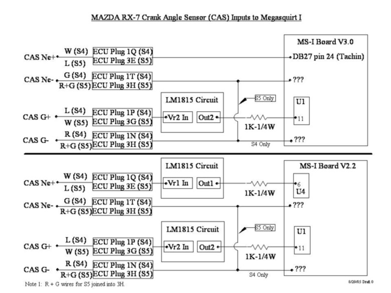
I was referring to this diagram (looks liek the Ne- and G- are heading to the MS board):
Last edited by dbgeek; Feb 12, 2006 at 05:37 PM.

Thread
Thread Starter
Forum
Replies
Last Post
edmcguirk
NE RX-7 Forum
3
May 30, 2018 06:50 PM
LongDuck
1st Generation Specific (1979-1985)
12
Oct 7, 2015 08:12 PM