
Megasquirt Can Stimulator Provide RPM Signal to VR Circuit?


Thread Starter
Full Member
Joined: Feb 2005
Posts: 235
Likes: 0
From: Ontario, Canada
Can Stimulator Provide RPM Signal to VR Circuit?
In step #55 of the instructions it says:
"If you have installed the VR input circuit jumpers in step #52, the stim is not currently designed to put out the sort of signal (AC) the VR circuit expects. However, by adjusting the pots at R52 and R56 ....... it should be working"
Here are my specs:
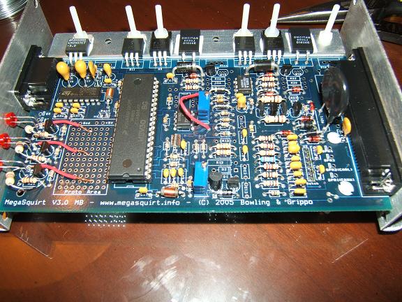
PCB: Version 3.0
Processor: MS II
RPM Input Circuit: Variable Reluctor (VR)
When I hook up the stimulator, all of the other inputs work (TPS, O2, IAT, CLT), but in MegaTune the RPM dial is a red color, and doesn't respond at all, even if I fiddle with R52 and R56.
"If you have installed the VR input circuit jumpers in step #52, the stim is not currently designed to put out the sort of signal (AC) the VR circuit expects. However, by adjusting the pots at R52 and R56 ....... it should be working"
Here are my specs:
PCB: Version 3.0
Processor: MS II
RPM Input Circuit: Variable Reluctor (VR)
When I hook up the stimulator, all of the other inputs work (TPS, O2, IAT, CLT), but in MegaTune the RPM dial is a red color, and doesn't respond at all, even if I fiddle with R52 and R56.
MegaSquirt Mod
Joined: Sep 2004
Posts: 4,721
Likes: 1
From: Maryland
you can't just "fiddle" with r52 and r56... you need to turn them both all the way counterclockwise.
another quick question? Why are you using the MS2? that doesn't have any support for rotary ignition at all... You'll really only be able to do fuel only, or EDIS, or something like that.
another quick question? Why are you using the MS2? that doesn't have any support for rotary ignition at all... You'll really only be able to do fuel only, or EDIS, or something like that.
Thread Starter
Full Member
Joined: Feb 2005
Posts: 235
Likes: 0
From: Ontario, Canada
Nice catch. It's for my friend's car. We're building his first and then mine. Mine is a MS I. Fiddle was his term. lol. I just copied his post from the MS forum in order to save time. We've tried going counterclockwise on R52 & R56 and still nothing. There must be something wrong with the circuit.
Last edited by sjd; Mar 8, 2006 at 11:34 PM.
MegaSquirt Mod
Joined: Sep 2004
Posts: 4,721
Likes: 1
From: Maryland
you have to go fully counterclockwise..
you also have to make sure you jumper everything right:
Jumper vrin to tachselect, and tsel to vrout or vroutinv... for the ms1 you want vroutinv... for the ms2 it doesn't matter.
you also have to make sure you jumper everything right:
Jumper vrin to tachselect, and tsel to vrout or vroutinv... for the ms1 you want vroutinv... for the ms2 it doesn't matter.
Rotary Enthusiast
Joined: Aug 2002
Posts: 850
Likes: 0
From: MO
i need an answer for this too. the manual says it wont work unless u mess with R52 and R56. i mess around with them and get nothing. they need to be full counter-clockwise when it is connected to the car it says. im trying to use the stimulator to make rpm in megatune. can this be accomplished when jumpered to use a VR sensor?
I'm in rotary heaven!
Joined: Dec 2006
Posts: 399
Likes: 0
From: jax
One good thing to do is bench test everything, even if it is installed in the car. Get your hands on a spare cas and plug it in and spin it by hand to make the sparks trigger. The stim is a usefull tool but setting up the dual vr's for me was a bit confusing because the first time I installed it i had two wires backwards triggering one of my trailing coils insted of the leading pack. Spinning the cas by hand lets you watch the plugs and see what's going on.
Just my opinion.
Just my opinion.
Trending Topics
Rotary Enthusiast
Joined: Aug 2002
Posts: 850
Likes: 0
From: MO
am i missing something?
i had to use a different transistor in Q23 but it had the same specs. ive put ms extra on it and have set all the settings like shown in the FAQ. i cannot get rpm to show up with the stim even when i have "stim for wheel" on.
where do i go next?
i had to use a different transistor in Q23 but it had the same specs. ive put ms extra on it and have set all the settings like shown in the FAQ. i cannot get rpm to show up with the stim even when i have "stim for wheel" on.
where do i go next?
MegaSquirt Mod
Joined: Sep 2004
Posts: 4,721
Likes: 1
From: Maryland
I've never had a problem getting RPM from the stim to the MS personally, even using the VR circuit.
If you use stim-for-wheel, and set it to "2," then hook up to the stim, you should get a signal...
Are you sure the stim isn't what's broken?
Do you have both of the pots turned fully counterclockwise? That has always worked for me, answering yes or no to that question... you just said you fiddled with them.
Ken
Rotary Enthusiast
Joined: Aug 2002
Posts: 850
Likes: 0
From: MO
yah i have them all the way left till they click. i did fiddle with them too cause thats what the manual says. i dunno if the stim or the circuit is broke then, is their no guides to diagnosing this? "X voltage on this part of the circuit" etc? i dont know how the vr circuit works, i THINK its suppose to take and AC wave and turn it into a square wave so MS can read it. but i dont know how the stim works etc
MegaSquirt Mod
Joined: Sep 2004
Posts: 4,721
Likes: 1
From: Maryland
The stim outputs a +12v square wave... the VR circuit should have no trouble reading this... you can verify that it's doing *something* if you have a multi-tester...
Just check voltage on the jumper from VRIN to TACHSELECT jumper... it should not be 12v or 0v, somewhere in between... even better would be to scope that same place, and make sure you're getting a good +12v square wave.
If your multitester has a duty cycle setting, it should change when turning the stim rpm pots.
Ken
MegaSquirt Mod
Joined: Sep 2004
Posts: 4,721
Likes: 1
From: Maryland
if you're using an ms1 and your VR sensor is wired correctly, then you should use vroutinv to tsel...
It has nothing to do with the vb921's... You only need vb921's if you're directly driving the coils though... if you use the stock 2nd gen or 3rd gen systems, you wont' need these.
Ken
It has nothing to do with the vb921's... You only need vb921's if you're directly driving the coils though... if you use the stock 2nd gen or 3rd gen systems, you wont' need these.
Ken

Full Member
Joined: Jul 2007
Posts: 116
Likes: 0
From: Hamilton, NZ
i am going to run cut tooth CAS with 3 vb921's wired
through LED 14 15 16 replacing the 4.7k resistor with a 200ohm for the leading
and two 330ohm - 400ohm for the trailing plugs
this way i wont have to run in inverted spark keeping the trailing split operational
through LED 14 15 16 replacing the 4.7k resistor with a 200ohm for the leading
and two 330ohm - 400ohm for the trailing plugs
this way i wont have to run in inverted spark keeping the trailing split operational


Thread
Thread Starter
Forum
Replies
Last Post
Jeff20B
1st Generation Specific (1979-1985)
73
Sep 16, 2018 07:16 PM
The1Sun
1st Generation Specific (1979-1985)
7
Sep 18, 2015 07:13 PM
The1Sun
New Member RX-7 Technical
5
Sep 15, 2015 04:45 PM
The1Sun
1st Generation Specific (1979-1985)
0
Sep 7, 2015 10:21 PM
rx8volks
Canadian Forum
0
Sep 1, 2015 11:02 PM