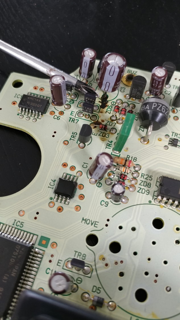
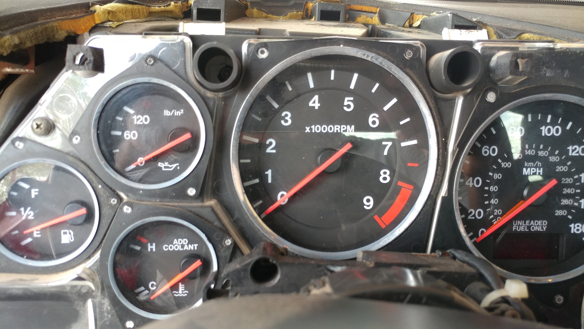
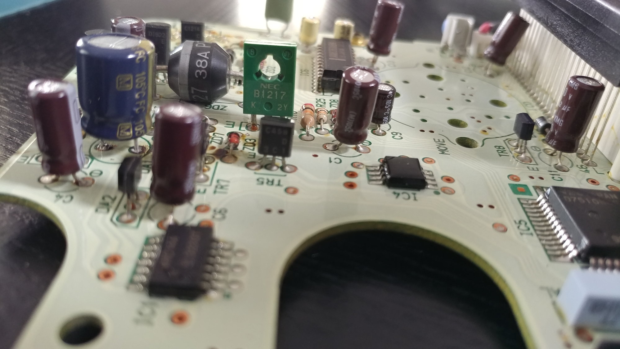
extremely simple FD tach/ odometer repair
#31
Everything in my cluster works except for the odometer, so I tried this fix today. The yellow/blue wire didn't have voltage when the key was on, but the black/yellow wire next to it did. So I used that black/yellow wire as my voltage source, and I tapped the ground into the cigarette lighter ground.
No change. Everything still works except for my odometer. I've already tried soldering in new capacitors behind the speedo. The odometer's back light lights up now, but I still just have faint 8s all the way across both lines.
No change. Everything still works except for my odometer. I've already tried soldering in new capacitors behind the speedo. The odometer's back light lights up now, but I still just have faint 8s all the way across both lines.
#32
So, have been carefully checking the published wiring diagrams and come to the following conclusions:
1) Ground that goes to the tachometer is pin 1E on the 8-pin connector at the back of the instrument panel. This is a Black wire with Blue stripe. This wire also goes through the X-18 20-pin Blue connector on the dash structure behind the instrument panel.
2) +12V power for the tachometer should come from Pin 2D on the 10-pin connector at the back of the instrument panel. This is a Black wire with Yellow stripe. This wire also goes through the X-18 20-pin Blue connector on the dash structure behind the instrument panel.
3) Signal for the tachometer should come from pin 3F on one of the 12-pin connectors at the back of the instrument panel. This is a Yellow wire with Blue stripe. Be careful because there is also a Blue wire with Yellow stripe on the other 12-pin connector, so make sure you get the colors right. The correct wire goes through a number of connectors back to pin 2B on the ECU. It also goes to the pin labeled IG- on the test connector in the engine bay.
Hopefully, that clears up the confusion about which wires should be connected to what and gives people options for jumpering to get the instruments working again.
The following users liked this post:
MilesBFree (02-23-23)
#34
Rotary Enthusiast
anyone had any oil pressure gauge issues that were the gauge and not the sender? I fixed my tach and now my oil gauge has died. I tried a second sender and it still doesn't work so I am pretty sure it is the gauge!?
#36
Super Moderator

iTrader: (1)
t-von,
Refer to these threads to help fix your odometer. Read them to its entirety. There are a lot of good info to take in.
just got done figuring out how fix fd odometer
FD Speedometer-Odometer Circuit Board - Odometer Components
Cheers,
George
Refer to these threads to help fix your odometer. Read them to its entirety. There are a lot of good info to take in.
just got done figuring out how fix fd odometer
FD Speedometer-Odometer Circuit Board - Odometer Components
Cheers,
George
The following users liked this post:
case (01-15-21)
#38
Super Moderator

iTrader: (1)
Any time. Glad to lend a hand. You may also want to use the ...fix odometer... thread for further updates to the repair.
I also recommend taking multiple angle photos of the circuit board since the speedo is removed. It may be useful on future repairs!
Cheers,
George
I also recommend taking multiple angle photos of the circuit board since the speedo is removed. It may be useful on future repairs!
Cheers,
George
#42
The tacho board normally gets its power from the speedo board. I've been testing my speedo/tacho boards recently. When I apply 12V to my speedo board it only outputs around 7V to the tacho board, so 12V appears to me to be more than the designers intended for the tacho board (though 12V may be perfectly safe as evidence from all those using 12V suggests). If I remember correctly, my tacho board functioned with even 6V power supply power when I was testing the board on my bench.
The following users liked this post:
Gen2n3 (09-02-17)
#43
Behold, reference oscilloscope data of the TAM signal at warm idle (~720rpm) from my stock FD (see photo). The pulsewidths are around 1.4ms and pulses are around 42ms apart. Looks like the ECU generates two tach pulses per output shaft revolution.
I note that the speedo board inputs the TAM signal and outputs a filtered version to the tacho board using an open collector (read "an interface powered by the tacho board",using "TR8" on the speedo board). Connecting TAM (a PCME powered signal) to the signal input of the tacho board is not what the designers intended, though it may be perfectly safe.
I note that the speedo board inputs the TAM signal and outputs a filtered version to the tacho board using an open collector (read "an interface powered by the tacho board",using "TR8" on the speedo board). Connecting TAM (a PCME powered signal) to the signal input of the tacho board is not what the designers intended, though it may be perfectly safe.
#44
I saw strange tacho and speedo needle glitches at first and eventually both gauges stopped working at all (needles did not move) and I got code 06 (No Speedometer Sensor Signal).
My speedo board's capacitor "C3" (1000uF) was leaking like others, but "IC4" (LM2903, comparators, used for sensor signal processing) was my main problem; it had partially failed such that "OUT2" had large noise when changing state. "OUT2" supplies processed speed sensor signals to the speedo board CPU (D751...,for the "4P" signal back to the PCME for code 06) and to the speedo motor driver chip (AN8363UBK) for making the speedo gauge needle move.
I note that the speedo board does not simply pass the TAM signal (instrument console connector 3F) through to the tacho board; connecting 3F directly to the tacho board signal screw is not what the designers intended, though I don't know if it's hazardous to the tacho board or PCME to do so.
Last edited by ALIENR2; 09-02-17 at 08:07 PM.
The following users liked this post:
Gen2n3 (09-02-17)
#45
I observed TAM using an oscilloscope. It looks like the PCME outputs two ~1.4ms tach pulses per output shaft revolution. The tach pulses appeared to be ~15V magnitude which seems large.
The following users liked this post:
Gen2n3 (09-02-17)
#46
Super Moderator

iTrader: (1)
AlienR2 (Jeff), Excellent troubleshooting work and nice schematic diagram!
I believe the depth of your research exceeds the scope of this particular thread, as it is meant to be a quick fix. However, I understand your caution and equally agree with it - directly wiring the tach via the mounting screws is a hazardous proposition that could easily cause more harm than good.
Since your information is detailed, may I suggest beginning a new thread to document your progress and allow others to follow in your footsteps? There is also a good amount of detailed info here: just got done figuring out how fix FD odometer that could also provide as reference material.
How did you trace out the IC4 circuit? Seriously, that was nice work!
Cheers,
George
#47
Super Moderator

iTrader: (1)
It would make sense that the +15V amplitude is used to drive the tachometer motor and its frequency determines the amount of deflection on the tach needle because the tach board also has an AN8363UBK chip (IC1 on the tach board).
#48
I saw strange tacho and speedo needle glitches at first and eventually both gauges stopped working at all (needles did not move) and I got code 06 (No Speedometer Sensor Signal).
My speedo board's capacitor "C3" (1000uF) was leaking like others, but "IC4" (LM2903, comparators, used for sensor signal processing) was my main problem; it had partially failed such that "OUT2" had large noise when changing state. "OUT2" supplies processed speed sensor signals to the speedo board CPU (D751...,for the "4P" signal back to the PCME for code 06) and to the speedo motor driver chip (AN8363UBK) for making the speedo gauge needle move.
I note that the speedo board does not simply pass the TAM signal (instrument console connector 3F) through to the tacho board; connecting 3F directly to the tacho board signal screw is not what the designers intended, though I don't know if it's hazardous to the tacho board or PCME to do so.
My speedo board's capacitor "C3" (1000uF) was leaking like others, but "IC4" (LM2903, comparators, used for sensor signal processing) was my main problem; it had partially failed such that "OUT2" had large noise when changing state. "OUT2" supplies processed speed sensor signals to the speedo board CPU (D751...,for the "4P" signal back to the PCME for code 06) and to the speedo motor driver chip (AN8363UBK) for making the speedo gauge needle move.
I note that the speedo board does not simply pass the TAM signal (instrument console connector 3F) through to the tacho board; connecting 3F directly to the tacho board signal screw is not what the designers intended, though I don't know if it's hazardous to the tacho board or PCME to do so.
that being said, I have been running my tach signal to the tach directly for a few years now, since I removed my speedo for a Speedhut gauge, I no longer have the factory speedo. I have had no issues with it.
Full disclaimer, I am LS1 swapped, so my tach signal is not a factory signal, either, it is from the LS1 pcm.
#49
AlienR2 (Jeff), Excellent troubleshooting work and nice schematic diagram!
I believe the depth of your research exceeds the scope of this particular thread, as it is meant to be a quick fix. However, I understand your caution and equally agree with it - directly wiring the tach via the mounting screws is a hazardous proposition that could easily cause more harm than good.
Since your information is detailed, may I suggest beginning a new thread to document your progress and allow others to follow in your footsteps? There is also a good amount of detailed info here: just got done figuring out how fix FD odometer that could also provide as reference material.
How did you trace out the IC4 circuit? Seriously, that was nice work!
Cheers,
George
I believe the depth of your research exceeds the scope of this particular thread, as it is meant to be a quick fix. However, I understand your caution and equally agree with it - directly wiring the tach via the mounting screws is a hazardous proposition that could easily cause more harm than good.
Since your information is detailed, may I suggest beginning a new thread to document your progress and allow others to follow in your footsteps? There is also a good amount of detailed info here: just got done figuring out how fix FD odometer that could also provide as reference material.
How did you trace out the IC4 circuit? Seriously, that was nice work!
Cheers,
George
Thanks!
I found that backlighting the circuit board was key to following the traces. A good flashlight will work; put the flashlight right on the board on one side and look at the board from the opposite side, with magnifying glass as needed. Components attached to the board are in the way (you can't always see where the traces go), so I also tested for continuity using a Digital Volt Meter as needed for confirmation.
#50
The 15V tach pulses seemed large to me because I expect automotive electronics signals to usually be less than 12V (i.e. battery voltage, which can be closer to 13V with a healthy battery, and up to 14V when the engine is running due to a healthy alternator, but 15V? Confirmation measurements from another car/oscilloscope/human desired, though the paragraph below includes a partial confirmation). Ignition signals (much higher than 12V) are a different story, of course. I note that the crankshaft position sensor plate (shown on sheet F-166 of "1994 Workshop Manual") only has one 'finger' sticking out of it for making the "G-signal", so my guess that the G-signal (one pulse per output shaft revolution) was the source of TAM (two pulses per rev) was wrong. Of course, the PCME could have been made to use the G and NE signals to make TAM with any number of pulses per rev.
While troubleshooting the speedo board I applied digital signals to the board inputs (where the ribbon cable connects) to try to test IC4 and found that 5V(0V Low and 5V High) signals resulted in very small amplitude signals at IC4 inputs (IN1+ and IN2+); I increased the voltage in steps and eventually was applying 12V signals and still the signals at IC4 inputs were small and not triggering IC4 outputs to change state, so I was really confused (wondering how many things were broken) until I observed that TAM was even larger than 12V. For testing IC4 outputs, it was easier to apply (4V) test signals directly to IC4 inputs (IN1+ and IN2+). IC4 runs on 5V (measured 5.2V).
My tacho board has an AN8352UBK, and my speedo board has an AN8363UBK. Both are clearly motor driver chips and have the same package (Skinny DIP22, so they will not fit into a normal breadboard, unfortunately) and maybe the same pin assignments. I'm curious if they can be used interchangeably, but I'll try that experiment when I don't have an exact replacement when I need one. These chips are non-commercial (i.e. hard to find new chips or even datasheets). I've found them at junkyards in 1994 and 1995 (and maybe other years have them too) Nissan Pathfinders (same applications in speedo and tacho boards). A manufacturing date code "11/95" Pathfinder still had a AN8352UBK on its tacho board (the printed board is identical to our board but has some different component values that look to me like it might use 12V supply power), but the speedo board design had changed and no longer had an AN8363UBK on it. I only started looking for an AN8363UBK because I thought mine might be failed (it was not failed) and then picked up a couple just in case, since they are hard to find.
One puzzle is that these chips connect to the speedo/tacho motors using 4 traces, so I assumed that the motors are stepper motors, but my oscilloscope does not show Hi-or-Low stepper driver signals like I would expect when measuring the 4 traces, so I'm not sure what kind of motors they are.


